This quick reference guide will assist you in locating a desired topic or pro- cedure. •Bend the pages back to match the black tab of the desired chapter num- ber with the black tab on the edge at each table of contents page. •Refer to the sectional table of contents for the exact pages to locate the spe- cific topic required. Quick Reference Guide General Information 1 Periodic Maintenance 2 Fuel System (DFI) 3 Cooling System 4 Engine Top End 5 Clutch 6 Engine Lubrication System 7 Engine Removal/Installation 8 Crankshaft/Transmission 9 Wheels/Tires 10 Final Drive 11 Brakes 12 Suspension 13 Steering 14 Frame 15 Electrical System 16 Appendix 17
LIST OF ABBREVIATIONS A ampere(s) lb pound(s) ABDC after bottom dead center m meter(s) AC alternating current min minute(s) ATDC after top dead center N newton(s) BBDC before bottom dead center Pa pascal(s) BDC bottom dead center PS horsepower BTDC before top dead center psi pound(s) per square inch °C degree(s) Celsius r revolution DC direct current rpm revolution(s) per minute F farad(s) TDC top dead center °F degree(s) Fahrenheit TIR total indicator reading ft foot, feet V volt(s) g gram(s) W watt(s) h hour(s) Ω ohm(s) L liter(s) Read OWNER’S MANUAL before operating.
Foreword This manual is designed primarily for use by trained mechanics in a properly equipped shop. However, it contains enough detail and basic in- formation to make it useful to the owner who de- sires to perform his own basic maintenance and repair work. A basic knowledge of mechanics, the proper use of tools, and workshop proce- dures must be understood in order to carry out maintenance and repair satisfactorily. When- ever the owner has insufficient experience or doubts his ability to do the work, all adjust- ments, maintenance, and repair should be car- ried out only by qualified mechanics. In order to perform the work efficiently and to avoid costly mistakes, read the text, thor- oughly familiarize yourself with the procedures before starting work, and then do the work care- fully in a clean area. Whenever special tools or equipment are specified, do not use makeshift tools or equipment. Precision measurements can only be made if the proper instruments are used, and the use of substitute tools may ad- versely affect safe operation. For the duration of the warranty period, we recommend that all repairs and scheduled maintenance be performed in accordance with this service manual. Any owner maintenance or repair procedure not performed in accordance with this manual may void the warranty. To get the longest life out of your vehicle. • Follow the Periodic Maintenance Chart in the Service Manual. • Be alert for problems and non-scheduled maintenance. • Use proper tools and genuine Kawasaki Mo- torcycle parts. Special tools, gauges, and testers that are necessary when servicing Kawasaki motorcycles are introduced by the Service Manual. Genuine parts provided as spare parts are listed in the Parts Catalog. • Follow the procedures in this manual care- fully. Don’t take shortcuts. • Remember to keep complete records of main- tenance and repair with dates and any new parts installed. How to Use This Manual In this manual, the product is divided into its major systems and these systems make up the manual’s chapters. The Quick Reference Guide shows you all of the product’s system and assists in locating their chapters. Each chapter in turn has its own comprehensive Ta- ble of Contents. For example, if you want ignition coil informa- tion, use the Quick Reference Guide to locate the Electrical System chapter. Then, use the Table of Contents on the first page of the chap- ter to find the Ignition Coil section. Whenever you see these WARNING and CAUTION symbols, heed their instructions! Always follow safe operating and maintenance practices. WARNING This warning symbol identifies special instructions or procedures which, if not correctly followed, could result in per- sonal injury, or loss of life. CAUTION This caution symbol identifies special instructions or procedures which, if not strictly observed, could result in dam- age to or destruction of equipment. This manual contains four more symbols (in addition to WARNING and CAUTION) which will help you distinguish different types of informa- tion. NOTE ○ This note symbol indicates points of par- ticular interest for more efficient and con- venient operation. • Indicates a procedural step or work to be done. ○ Indicates a procedural sub-step or how to do the work of the procedural step it follows. It also precedes the text of a NOTE. Indicates a conditional step or what action to take based on the results of the test or inspec- tion in the procedural step or sub-step it fol- lows. In most chapters an exploded view illustration of the system components follows the Table of Contents. In these illustrations you will find the instructions indicating which parts require spec- ified tightening torque, oil, grease or a locking agent during assembly.
GENERAL INFORMATION 1-1 1 General Information Table of Contents Before Servicing ..................................................................................................................... 1-2 Model Identification................................................................................................................. 1-7 General Specifications............................................................................................................ 1-9 Technical Information - Cassette Type Transmission ............................................................. 1-12 Technical Information - Inlet Air Pressure Sensor ................................................................. 1-13 Technical Information – ABS (Anti – Lock Brake System) ...................................................... 1-14 Unit Conversion Table ............................................................................................................ 1-26
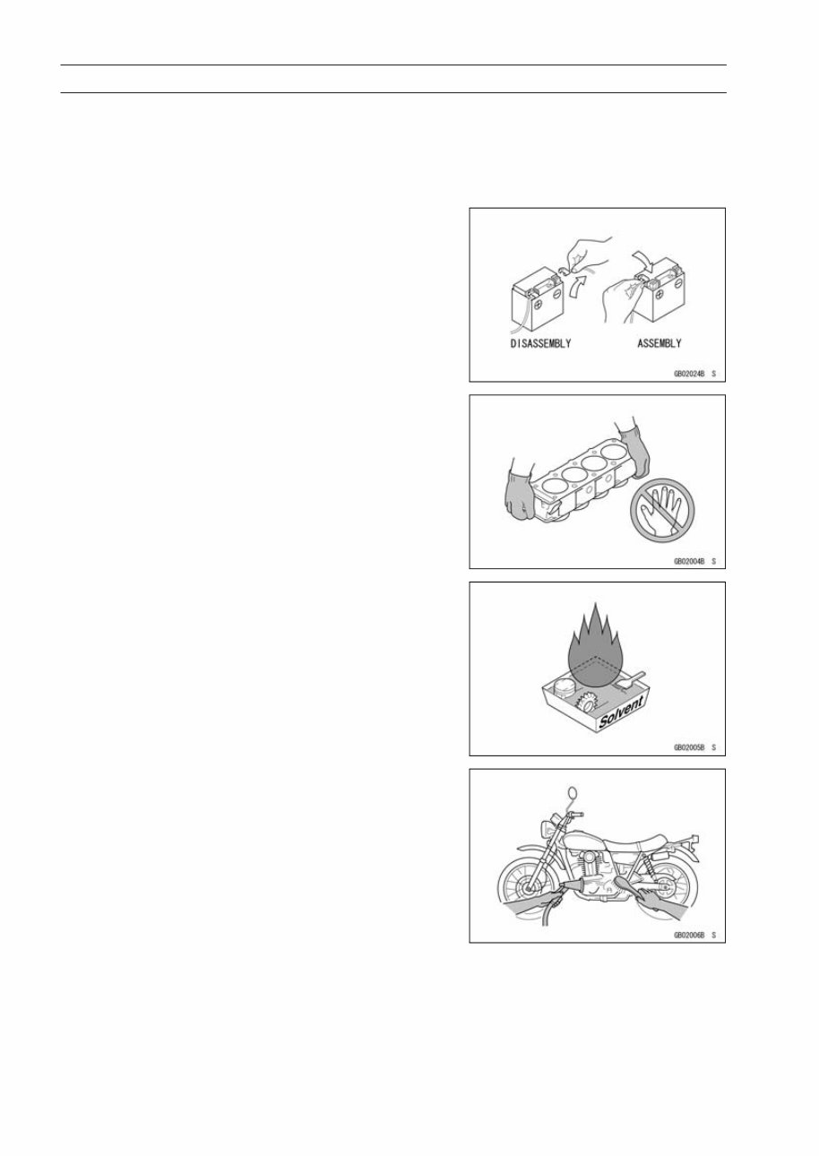
1-2 GENERAL INFORMATION Before Servicing Before starting to perform an inspection service or carry out a disassembly and reassembly opera- tion on a motorcycle, read the precautions given below. To facilitate actual operations, notes, illustra- tions, photographs, cautions, and detailed descriptions have been included in each chapter wherever necessary. This section explains the items that require particular attention during the removal and reinstallation or disassembly and reassembly of general parts. Especially note the following: Battery Ground Before completing any service on the motorcycle, discon- nect the battery cables from the battery to prevent the en- gine from accidentally turning over. Disconnect the ground cable (–) first and then the positive (+). When completed with the service, first connect the positive (+) cable to the positive (+) terminal of the battery then the negative (–) ca- ble to the negative terminal. Edges of Parts Lift large or heavy parts wearing gloves to prevent injury from possible sharp edges on the parts. Solvent Use a high-flush point solvent when cleaning parts. High -flush point solvent should be used according to directions of the solvent manufacturer. Cleaning Vehicle before Disassembly Clean the vehicle thoroughly before disassembly. Dirt or other foreign materials entering into sealed areas during ve- hicle disassembly can cause excessive wear and decrease performance of the vehicle.
2007 Kawasaki ER-6n OEM Service & Repair Manual is a comprehensive resource for repairing and adjusting your Kawasaki ER-6n. It serves as a valuable reference for professional mechanics and DIY enthusiasts alike. The manual provides detailed, step-by-step explanations for installation, removal, disassembly, assembly, repair, and check procedures in a systematic order.
This manual is also known as the Kawasaki ER-6n OEM service manual, repair manual, workshop manual, and shop manual – all referring to the same complete guide.
The manual is organized into chapters that cover specific aspects of the Kawasaki ER-6n, including:
General Information
Periodic Maintenance
Fuel System (DFI)
Cooling System
Engine Top End
Clutch
Engine Lubrication System
Engine Removal/Installation
Crankshaft/Transmission
Wheels/Tires
Final Drive
Brakes
Suspension
Steering
Frame
Electrical System
Appendix
Each chapter is further divided into sections and sub-sections, with exploded diagrams provided at the beginning of each removal and disassembly section to assist in part identification and clarify procedures. The manual is available in PDF format, allowing you to easily print specific pages or the entire manual as required.