

2007-2012 Hyosung Ms3 125 250 Scooter Service & Repair Manual
What's Included?
Fast Download Speeds
Online & Offline Access
Access PDF Contents & Bookmarks
Full Search Facility
Print one or all pages of your manual
ELECTRICAL SYSTEM
COOLING SYSTEM
GROUP INDEX
GENERAL INFORMATION
1
PERIODIC MAINTENANCE
2
ENGINE
3
FI SYSTEM DIAGNOSIS
4
FUEL SYSTEM AND THROTTLE BODY
5
6
7
CHASSIS
8
SERVICING INFORMATION
9
� COPYRIGHT S&T Motors Co., Ltd.
FOREWORD
This manual contains an introductory description on
HYOSUNG and procedures
for its inspection/service and overhaul of its main
components.
Other information considered as generally known is
not included.
Read GENERAL INFORMATION section to familiar-
ize yourself with outline of the vehicle and MAINTE-
NANCE and other sections to use as a guide for
proper inspection and service.
This manual will help you know the vehicle better so
that you can assure your customers of your optimum
and quick service.
WARNING
This manual is intended for those who have
enough knowledge and skills for servicing
HYOSUNG vehicles. Without such knowledge and
skills, you should not attempt servicing by relying
on this manual only.
Instead, please contact your nearby authorized
HYOSUNG motorcycle dealer.
� This manual has been prepared on the basis of
the latest specification at the time of publica-
tion.
If modification has been made since then,
difference may exist between the content of
this manual and the actual vehicle.
� Illustrations in this manual are used to show
the basic principles of operation and work pro-
cedures.
They may not represent the actual vehicle
exactly in detail.
COPYRIGHTED
HOW TO USE THIS MANUAL
TO LOCATE WHAT YOU ARE LOOKING FOR :
1. The text of this manual is divided into sections.
2. As the title of these sections is listed on the previous page as
GROUP INDEX, select the section where you are looking for.
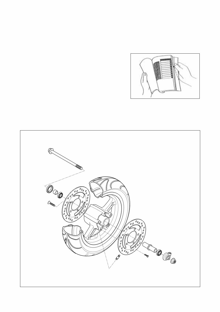
3. Holding the manual as shown at the right will allow you to find
the first page of the section easily.
4. On the first page of each section, its contents are listed. Find
the item and page you need.
COMPONENT PARTS
Example : Front wheel
COPYRIGHTED
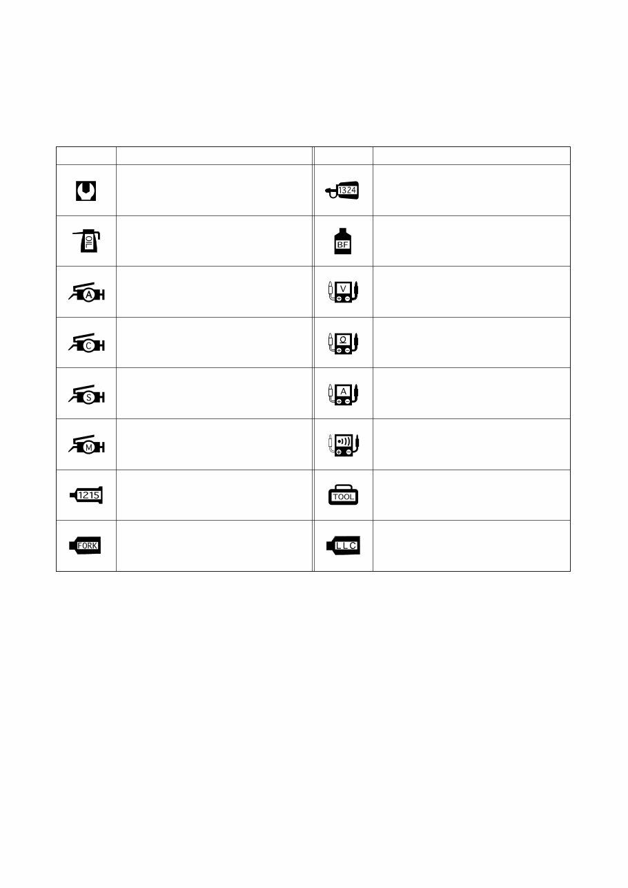
SYMBOL
Listed in the table below are the symbols indicating instructions and other information necessary for servicing and
meaning associated with them respectively.
Apply THREAD LOCK “1324” .
Apply or use brake fluid.
Measure in voltage range.
Measure in resistance range.
Measure in current range.
Use special tool.
Use engine coolant.
Torque control required.
Data beside it indicates specified torque.
Apply oil.
Use engine oil unless otherwise specified.
Apply SUPER GREASE “A” .
Apply SILICONE GREASE.
Apply MOLY PASTE.
Apply BOND “1215” .
Use fork oil.
DEFINITION SYMBOL DEFINITION SYMBOL
Apply SUPER GREASE “C” .
Measure in continuity test range.
COPYRIGHTED

A
ABDC : After Bottom Dead Center
AC : Alternating Current
API : American Petroleum Institute
ATDC : After Top Dead Center
B
BBDC : Before Bottom Dead Center
BDC : Bettom Dead Center
BTDC : Before Top Dead Center
D
DC : Direct Current
DOHC : Double Over Head Camshaft
E
ECU : Engine Control Unit,
FI Control Unit
F
FI : Fuel Injection, Fuel Injector
FP : Fuel Pump
I
IAP Sensor : Intake Air Pressure Sensor
(IAPS)
IAT Sensor : Intake Air Temperature Sensor
(IATS)
IG : Ignition
ISC Solenoid : Idle Speed Control Solenoid
L
LCD : Liquid Crystal Display
LED : Light Emitting Diode
LH : Left Hand
M
Max : Maximum
Min : Minimum
O
O2 Sensor : Oxygen Sensor (O2S)
R
RH : Right Hand
S
SAE : Society of Automotive Engineers
SAV Solenoid : Secondary Air Valve Solenoid
T
TDC : Top Dead Center
TO Sensor : Tip Over Sensor (TOS)
TP Sensor : Throttle Position Sensor (TPS)
W
WT Sensor : Water Temperature Sensor
(WTS)
ABBREVIATIONS USED IN THIS MANUAL
COPYRIGHTED

BL : Black with Blue tracer BBr : Black with Brown tracer
BG : Black with Green tracer BO : Black with Orange tracer
BR : Black with Red tracer BW : Black with White tracer
BY : Black with Yellow tracer LB : Blue with Black tracer
LG : Blue with Green tracer LR : Blue with Red tracer
LW : Blue with White tracer LY : Blue with Yellow tracer
BrB : Brown with Black tracer BrW : Brown with White tracer
GB : Green with Black tracer GR : Green with Red tracer
GY : Green with Yellow tracer GrB : Gray with Black tracer
GrR : Gray with Red tracer GrW : Gray with White tracer
OB : Orange with Black tracer OL : Orange with Blue tracer
OG : Orange with Green tracer OR : Orange with Red tracer
OW : Orange with White tracer OY : Orange with Yellow tracer
RB : Red with Black tracer RW : Red with White tracer
WB : White with Black tracer WL : White with Blue tracer
WR : White with Red tracer YB : Yellow with Black tracer
YL : Yellow with Blue tracer YG : Yellow with Green tracer
YR : Yellow with Red tracer
B : Black Gr : Gray Sb : Light blue
L : Blue Lg : Light green W : White
Br : Brown O : Orange Y : Yellow
G : Green R : Red
WIRE COLOR
COPYRIGHTED
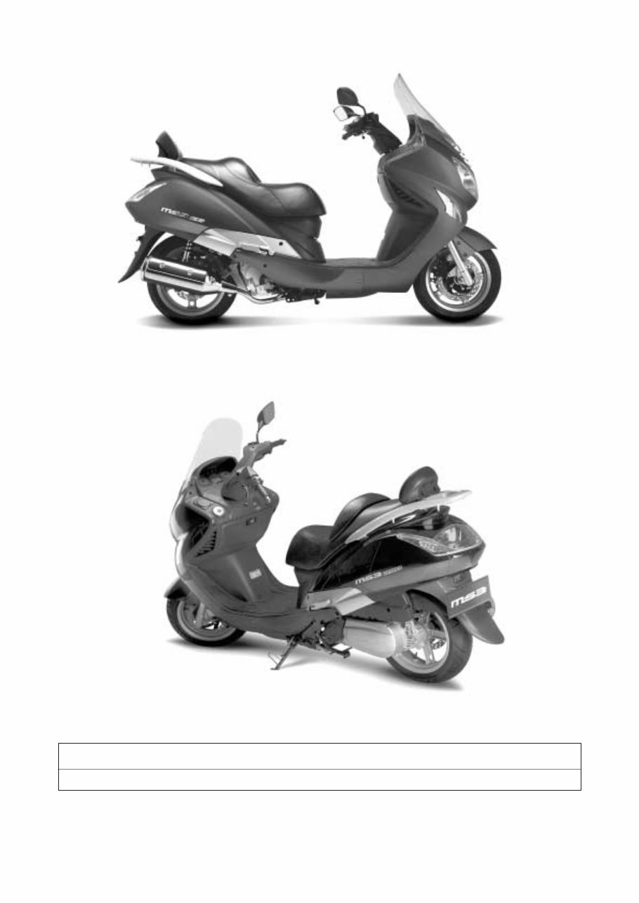
NOTE
Difference between photographs and actual motorcycles depends on the markets.
COPYRIGHTED

GENERAL INFORMATION
INFORMATION LABELS ………………………………………………… 1- 1
GENERAL PRECAUTIONS …………………………………………… 1- 2
SERIAL NUMBER LOCATION ………………………………………… 1- 3
FUEL, OIL AND ENGINE COOLANT RECOMMENDATIONS …… 1- 4
BREAK-IN PROCEDURES……………………………………………… 1- 6
EXTERIOR ILLUSTRATION …………………………………………… 1- 7
SPECIFICATIONS ………………………………………………………… 1- 8
CONTENTS
1
COPYRIGHTED
1-1 GENERAL INFORMATION
Please note, however, that the warning and cautions contained in this manual cannot possibly cover all potential
hazards relating to the servicing, or lack of servicing, of the motorcycle. In addition to the WARNING and CAUTION
stated, you must use good judgement and basic mechanical safety principles. If you are unsure about how to per-
form a particular service operation, ask a more experienced mechanic for advice.
WARNING / CAUTION / NOTE
Please read this manual and follow its instructions carefully.
To emphasize special information, the symbol and the words WARNING, CAUTION and NOTE have special mean-
ings. Pay special attention to the messages highlighted by these signal words.
CAUTION
Indicates a potential hazard that could result in vehicle damage.
WARNING
Indicates a potential hazard that could result in death or injury.
NOTE
Indicates special information to make maintenance easier or instructions cleaner.
COPYRIGHTED

GENERAL INFORMATION 1-2
GENERAL PRECAUTIONS
WARNING
� Proper service and repair procedures are important for the safety of the service machanic and the safety
and reliability of the vehicle.
� When 2 or more persons work together, pay attention to the safety of each other.
� When it is necessary to run the engine indoors, make sure that exhaust gas is forced outdoors.
� When working with toxic or flammable materials, make sure that the area you work in is well-ventilated and
that you follow all off the material manufacturer’s instructions.
� Never use gasoline as a cleaning solvent.
� To avoid getting burned, do not touch the engine, engine oil, exhaust system or radiator during or for a
while after engine operation.
� After servicing fuel, oil, engine coolant, exhaust or brake systems, check all lines and fittings related to the
system for leaks.
WARNING
� If parts replacement is necessary, replace the parts with HYOSUNG Genuine Parts or their equivalent.
� When removing parts that are to be reused, keep them arranged in an orderly manner so that they may be
reinstalled in the proper order and orientation.
� Be sure to use special tools when instructed.
� Make sure that all parts used in reassembly are clean, and also lubricated when specified.
� When use of a certain type of lubricant, bond, or sealant is specified, be sure to use the specified type.
� When removing the battery, disconnect the � battery lead wire first and then the � battery lead wire.
When reconnecting the battery, connect the � battery lead wire first and then the � battery lead wire.
Finally, cover the � battery terminal with the terminal cover.
� When performing service to electrical parts, if the service procedures do not require use of battery power,
diconnect the � battery lead wire at the battery.
� Tighten cylinder head and case bolts and nuts, beginning with larger diameter and ending with smaller
diameter, from inside to outside diagonally, to the specified tightening torque.
� Whenever you remove oil seals, gaskets, packing, O-rings, locking washers, cotter pins, circlips, and cer-
tain other parts as specified, be sure to replace them with new ones. Also, before installing these new
parts, be sure to remove any material left over from the mating surfaces.
� Never reuse a circlip. When installing a new circlip, take care not to expand the end gap larger than
required to slip the circlip over the shaft. After installing a circlip, always ensure that it is completely seated
in its groove and securely fitted.
� Do not use self-locking nuts a few times over.
� Use a torque wrench to tighten fasteners to the torque values when specified. Wipe off grease or oil if a
thread is smeared with them.
� After reassembly, check parts for tightness and operation.
WARNING
� To protect environment, do not unlawfully dispose of used motor oil and other fluids: batteries, and tires.
� To protect Earth’s natural resouces, properly dispose of used vehicles and parts.
COPYRIGHTED
1-3 GENERAL INFORMATION
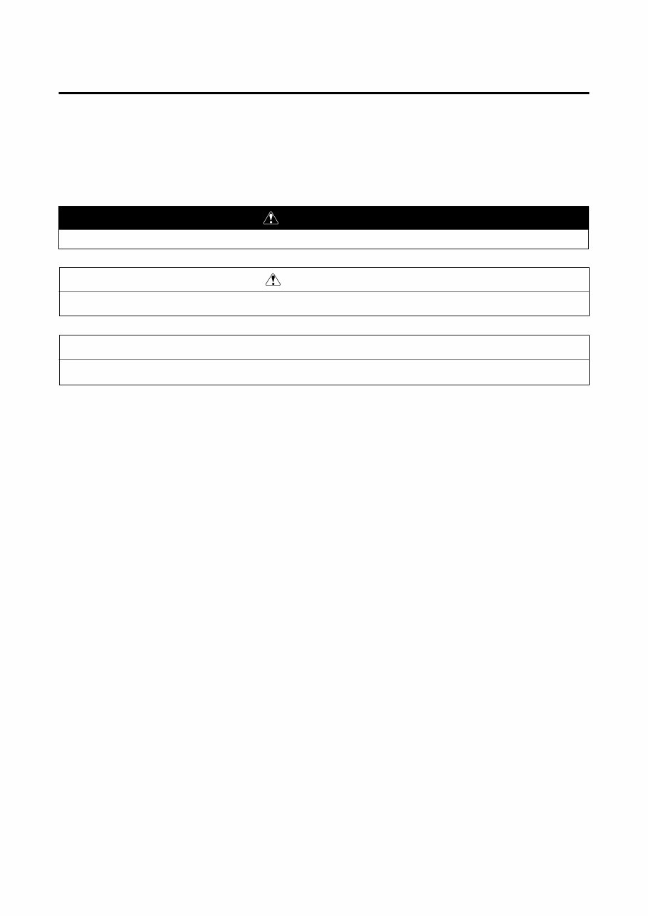
SERIAL NUMBER LOCATION
The frame serial number or V.I.N. (Vehicle Identification Number) is stamped on the right downside frame.
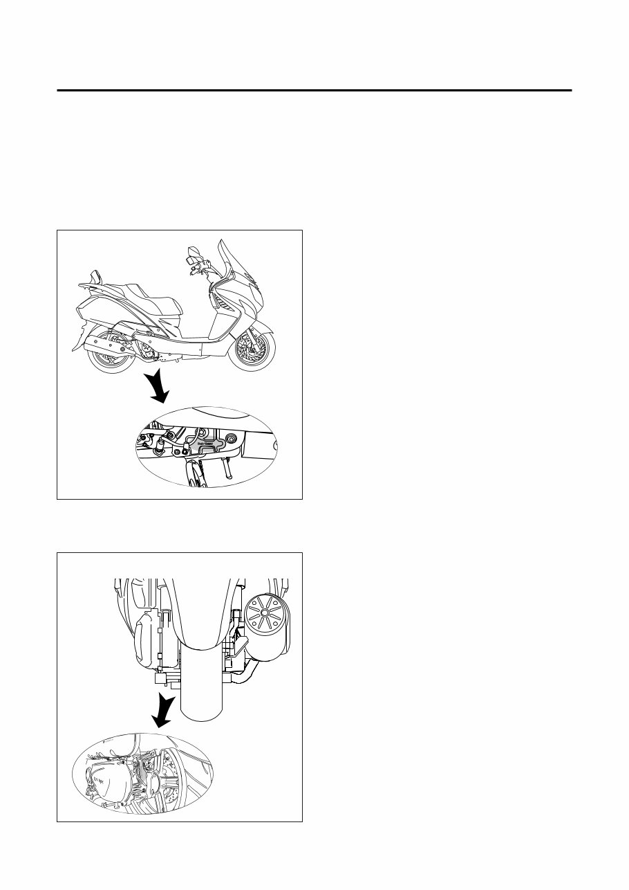
The engine serial number is stamped on the left rearside of the crankcase assembly.
These numbers are required especially for registering the machine and ordering spare parts.
◉ FRAME SERIAL NUMBER
◉ ENGINE SERIAL NUMBER
COPYRIGHTED
You're Reading a Preview
What's Included?
Fast Download Speeds
Online & Offline Access
Access PDF Contents & Bookmarks
Full Search Facility
Print one or all pages of your manual
$31.99
Viewed 17 Times Today


Secure transaction
What's Included?
Fast Download Speeds
Online & Offline Access
Access PDF Contents & Bookmarks
Full Search Facility
Print one or all pages of your manual
$31.99
Get instant access to the Complete Factory Service Repair Workshop Manual without any extra fees or expiry dates. This Professional Manual is suitable for both professional Mechanics and DIY enthusiasts, covering all repairs, servicing, and troubleshooting procedures with step-by-step instructions, detailed photos, diagrams, and highly detailed exploded diagrams & pictures.
Print out a single page or the entire manual as per your choice. The Manual can be used on multiple computers without any limitations or trial periods and can be used for life without the need to renew or pay any extra. It is fully compatible with all Windows & MAC Computers.
Click the button to get your hands on this comprehensive manual.


