

2009-2012 Husaberg FE 450 FE 570 Bike Service & Repair Manual
What's Included?
Fast Download Speeds
Offline Viewing
Access Contents & Bookmarks
Full Search Facility
Print one or all pages of your manual
REPAIR MANUAL
FE 450 EU
FE 450 AUS
FE 450 USA
FE 570 EU
FE 570 AUS
FE 570 USA
2009
Article no. 3803004en


INTRODUCTION 1
INTRODUCTION
It is important that you read this owner's manual carefully and completely before the start of work.
Only use ORIGINAL HUSABERG SPARE PARTS.
This vehicle can only fulfill the demands placed on it in the long run if the specified service work is performed regularly by qualified
experts.
The repair manual was written to correspond to the most current state of this model series. We reserve the right to make changes in
the interest of technical advancement without, at the same time, updating this repair manual.
We shall not provide a description of general workshop methods. Likewise, safety rules that apply in a workshop are not specified here.
It is assumed that repair work will be performed by a fully trained mechanic.
All specifications are non-binding. HUSABERG, a division of KTM SMC AG (referred to herein as HUSABERG), specifically reserves
the right to modify or delete technical specifications, prices, colors, forms, materials, services, designs, equipment, etc., without prior
notice and without specifying reasons, to adapt these to local conditions, as well as to stop production of a particular model without
prior notice. HUSABERG accepts no liability for delivery options, deviations from illustrations and descriptions or misprints and other
errors. The models portrayed partly contain special equipment that does not belong to the regular scope of delivery.
© 2008 by HUSABERG eine Division der KTM SMC AG, Mattighofen Austria
All rights reserved
Reproduction, even in part, is permitted only with the express written permission of the copyright owner.
ISO 9001(12 100 6061)
Within the meaning of the international quality management standard ISO 9001, HUSABERG uses quality assurance
processes that lead to the maximum possible quality of the products.
Issued by: TÜV Management Service
HUSABERG eine Division der KTM SMC AG
5230 Mattighofen, Austria

CONTENTS 2
CONTENTS
MEANS OF REPRESENTATION ............................................ 5
IMPORTANT NOTES ............................................................ 6
LOCATION OF SERIAL NUMBERS ........................................ 7
Chassis number ............................................................... 7
Type label (FE EU, FE AUS) ............................................. 7
Type label (FE USA) ........................................................ 7
Key number (FE EU, FE AUS)........................................... 7
Engine number................................................................ 7
Fork part number............................................................. 8
Shock absorber part number ............................................. 8
MOTORCYCLE..................................................................... 9
Jacking up the motorcycle ................................................ 9
Removing the motorcycle from the work stand .................... 9
Starting .......................................................................... 9
01/FORK, TRIPLE CLAMP.................................................. 10
Adjusting the compression damping of the fork ................ 10
Adjusting the rebound damping of the fork....................... 10
Adjusting the spring preload of the fork ........................... 10
Bleeding the fork legs .................................................... 11
Cleaning the dust boots of the fork legs ........................... 11
Loosening the fork protection.......................................... 11
Positioning the fork protection ........................................ 12
Removing the fork legs................................................... 12
Installing the fork legs ................................................... 12
Removing the fork protector............................................ 13
Installing the fork protector ............................................ 13
Performing a fork service ................................................ 14
Disassembling the fork legs ............................................ 14
Cartridge disassembly .................................................... 17
Disassembling the compression damping fitting ............... 19
Checking the fork legs.................................................... 19
Assembling the compression damping fitting.................... 20
Assembling the cartridge ................................................ 21
Assembling the fork legs ................................................ 23
Greasing the steering head bearing.................................. 27
Removing the lower triple clamp ..................................... 27
Installing the lower triple clamp ...................................... 28
Checking the play of the steering head bearing ................. 29
Adjusting the play of the steering head bearing ................ 29
03/FRAME ........................................................................ 30
Removing the engine guard ............................................ 30
Installing the engine guard ............................................. 30
04/SHOCK ABSORBER, SWINGARM................................... 31
Adjusting the high-speed compression damping of the
shock absorber .............................................................. 31
Adjusting the low-speed compression damping of the
shock absorber .............................................................. 31
Adjusting the rebound damping of the shock absorber....... 32
Measuring rear wheel sag unloaded ................................. 32
Checking the static sag of the shock absorber .................. 32
Checking the riding sag of the shock absorber .................. 33
Adjusting the spring preload of the shock absorber ........... 33
Adjusting the riding sag ................................................. 34
Removing the shock absorber ......................................... 34
Installing the shock absorber .......................................... 34
Performing a shock absorber service ................................ 35
Removing the spring ...................................................... 35
Disassembling the shock absorber ................................... 36
Disassembling the piston rod .......................................... 37
Disassembling the seal ring retainer ................................ 38
Replacing the pilot bushing ............................................ 39
Checking the shock absorber .......................................... 39
Disassembling the rebound adjuster ................................ 40
Removing the heim joint ................................................ 41
Installing the heim joint ................................................. 41
Assembling the rebound adjuster .................................... 42
Assembling the seal ring retainer .................................... 43
Assembling the piston rod .............................................. 43
Assembling the shock absorber ....................................... 45
Bleeding and filling the shock absorber ........................... 47
Filling the shock absorber with nitrogen ........................... 49
Installing the spring ....................................................... 50
Removing the swingarm, with shock absorber and rear
wheel ........................................................................... 51
Installing the swingarm, with shock absorber and rear
wheel ........................................................................... 52
05/EXHAUST .................................................................... 54
Removing the main silencer............................................ 54
Installing the main silencer ............................................ 54
Removing the exhaust system ......................................... 54
Installing the exhaust system.......................................... 55
06/AIR FILTER.................................................................. 57
Removing the air filter ................................................... 57
Installing the air filter .................................................... 57
Cleaning air filter........................................................... 57
07/FUEL TANK, SEAT, TRIM.............................................. 59
Removing the seat ......................................................... 59
Mounting the seat ......................................................... 59
Removing the fuel tank .................................................. 59
Installing the fuel tank ................................................... 60
Removing the spoiler ..................................................... 61
Installing the spoiler ...................................................... 61
Checking the fuel pressure ............................................. 62
08/MASK, FENDER, DECAL ............................................... 63
Removing the front fender .............................................. 63
Installing the front fender ............................................... 63
Removing the start number plate (FE USA) ...................... 63
Installing the start number plate (FE USA) ....................... 64
09/FRONT WHEEL ............................................................ 65
Removing the front wheel ............................................... 65
Installing the front wheel................................................ 65
Checking the tire air pressure ......................................... 66
Checking the tire condition............................................. 66
Checking the brake disks................................................ 67
10/REAR WHEEL .............................................................. 68
Removing the rear wheel ................................................ 68
Installing the rear wheel ................................................. 68
Checking the chain tension ............................................ 69
Adjusting the chain tension ............................................ 69
Checking the chain wear ................................................ 70
Checking the rear sprocket/engine sprocket for wear ......... 71
Checking for chain dirt accumulation .............................. 71
Cleaning the chain......................................................... 71
Adjusting the chain guide............................................... 72
Checking the spoke tension ............................................ 72
11/WIRING HARNESS, BATTERY ....................................... 73
Disconnecting the negative cable of the battery ................ 73
Connecting the negative cable of the battery .................... 73
Changing the main fuse ................................................. 73
Changing the fuses of individual power consumers............ 74
Removing the battery ..................................................... 75
Installing the battery ...................................................... 75
Charging the battery ...................................................... 76

CONTENTS 3
13/BRAKE SYSTEM........................................................... 78
Checking the free travel of the hand brake lever ............... 78
Adjusting the free travel of the handbrake lever (FE EU,
FE AUS) ....................................................................... 78
Adjusting the basic position of the handbrake lever
(FE USA) ...................................................................... 78
Checking the front brake fluid level ................................. 79
Adding front brake fluid ................................................. 79
Checking the front brake linings...................................... 80
Changing the front brake linings ..................................... 80
Checking the free travel of the foot brake lever ................. 82
Adjusting the basic position of the footbrake lever ............ 82
Checking the rear brake fluid level .................................. 83
Adding rear brake fluid .................................................. 83
Checking the rear brake linings ....................................... 84
Changing the rear brake linings ....................................... 84
14/LIGHTING SYSTEM, INSTRUMENTS ............................. 86
Adjusting the speedometer functions ............................... 86
Setting kilometers or miles ............................................. 86
Activating the additional functions .................................. 87
Setting the wheel circumference ..................................... 87
Setting the clock ........................................................... 88
Removing the headlight mask with the headlight (FE EU,
FE AUS) ....................................................................... 88
Installing the headlight mask with the headlight (FE EU,
FE AUS) ....................................................................... 88
Checking the headlight adjustment (FE EU, FE AUS) ........ 89
Adjusting the beam width of the headlight (FE EU,
FE AUS) ....................................................................... 89
Changing the headlight bulb (FE EU, FE AUS) ................. 89
30/ENGINE....................................................................... 91
Removing the engine ..................................................... 91
Installing the engine ...................................................... 94
30/ENGINE DISASSEMBLY................................................ 99
Clamping the engine in the engine work stand.................. 99
Draining the engine oil ................................................... 99
Removing the oil line ..................................................... 99
Removing the starter motor ............................................ 99
Removing the oil filter.................................................... 99
Removing the valve cover ............................................. 100
Removing the spark plug .............................................. 100
Removing the generator cover ....................................... 100
Positioning the engine at ignition top dead center
(TDC) ......................................................................... 100
Removing the timing chain tensioner ............................. 101
Removing the camshaft ................................................ 101
Removing the cylinder head.......................................... 102
Removing the piston .................................................... 102
Removing the distance bushing .................................... 102
Removing the rotor ...................................................... 103
Removing the balance weight ....................................... 103
Removing the timing chain guide rail ............................ 103
Removing the timing chain tensioning rail...................... 103
Removing the timing chain securing guide ..................... 104
Removing the timing chain ........................................... 104
Removing the ignition pulse generator ........................... 104
Removing the water pump cover ................................... 104
Removing the clutch cover ........................................... 104
Disassembling the clutch disks ..................................... 105
Removing the primary gear nut ..................................... 105
Removing the outer clutch hub ..................................... 106
Removing the balancer shaft ........................................ 106
Removing the primary gear ........................................... 106
Removing the free wheel gear ....................................... 107
Removing the torque limiter ......................................... 107
Removing the starter idler gear ..................................... 107
Removing the oil pump gears........................................ 107
Removing the oil pumps............................................... 108
Removing the shift shaft .............................................. 108
Removing the shift drum locating unit ........................... 108
Removing the locking lever ........................................... 108
Removing the left section of the engine case .................. 109
Removing the shift rails ............................................... 109
Removing the shift drum .............................................. 109
Removing the shift forks .............................................. 109
Removing the diaphragm.............................................. 110
Removing the transmission shafts ................................. 110
Removing the crankshaft .............................................. 110
30/ENGINE - WORK ON THE INDIVIDUAL PARTS ............. 111
Working on the right section of the engine case .............. 111
Working on the left section of the engine case ................ 112
Removing the oil pressure regulator valve....................... 113
Checking the spring length of the oil pressure regulator
valve .......................................................................... 113
Installing the oil pressure regulator valve ....................... 113
Removing the crankshaft seal ring in the clutch cover ..... 113
Installing the crankshaft seal ring in the clutch cover ...... 114
Removing the water pump ............................................ 114
Installing the water pump............................................. 115
Checking the balancer shaft ......................................... 115
Removing the timing chain sprocket .............................. 116
Installing the timing chain sprocket............................... 116
Removing the crankshaft bearing inner ring.................... 116
Installing the crankshaft bearing inner ring .................... 117
Changing the conrod bearing ........................................ 117
Checking the crankshaft run-out at the bearing pin ......... 119
Measuring the crankshaft end play ................................ 119
Checking/measuring the cylinder ................................... 120
Checking/measuring the piston ..................................... 120
Checking the piston ring end gap .................................. 121
Piston/cylinder - determining the mounting clearance ..... 121
Checking the oil pumps for wear ................................... 122
Disassembling the autodecompressor ............................ 122
Assembling the autodecompressor................................. 123
Checking the camshaft................................................. 123
Checking the timing assembly ...................................... 124
Preparing the timing chain tensioner for installation ....... 124
Removing the coolant temperature sensor ...................... 125
Removing the rocker arm.............................................. 125
Removing the valves .................................................... 125
Changing the camshaft bearing ..................................... 126
Checking the valves ..................................................... 127
Checking the valve springs ........................................... 127
Checking the valve spring seat ...................................... 127
Checking the cylinder head .......................................... 128
Installing the valves ..................................................... 128
Installing the rocker arm .............................................. 129
Installing the coolant temperature sensor ....................... 129
Checking the clutch ..................................................... 130
Checking the shift mechanism ...................................... 131
Preassembling the shift shaft........................................ 132
Disassembling the main shaft ....................................... 132
Assembling the main shaft ........................................... 132
Disassembling the countershaft .................................... 133

CONTENTS 4
Assembling the countershaft......................................... 133
Checking the transmission............................................ 134
Checking the electric starter mode ................................ 135
Removing the free wheel .............................................. 135
Installing the free wheel ............................................... 136
30/ENGINE ASSEMBLY ................................................... 137
Installing the crankshaft............................................... 137
Installing the transmission shafts .................................. 137
Installing the diaphragm .............................................. 137
Installing the shift fork................................................. 138
Installing the shift drum............................................... 138
Installing the shift rails ................................................ 138
Installing the left engine case ....................................... 138
Installing the locking lever............................................ 139
Installing the shift drum locating unit ............................ 139
Installing the shift shaft ............................................... 139
Installing the oil pumps ............................................... 140
Installing the oil pump gears ........................................ 140
Installing the starter idler gear ...................................... 140
Installing the torque limiter .......................................... 141
Installing the free wheel gear ........................................ 141
Installing the primary gear ............................................ 141
Installing the balancer shaft ......................................... 141
Installing the outer clutch hub ...................................... 141
Installing the primary gear nut ...................................... 142
Installing the clutch discs ............................................ 142
Installing the clutch cover ............................................ 143
Installing the water pump cover .................................... 143
Installing the ignition pulse generator ............................ 143
Installing the timing chain............................................ 144
Installing the timing chain securing guide ...................... 144
Installing the timing chain tensioning rail ...................... 144
Installing the timing chain guide rail ............................. 144
Installing the balance weight ........................................ 144
Installing the rotor ....................................................... 145
Installing the distance bushing ..................................... 145
Installing the piston ..................................................... 145
Installing the cylinder head .......................................... 147
Installing the camshaft ................................................ 148
Installing the timing chain tensioner ............................. 148
Checking the valve clearance ........................................ 148
Adjusting the valve clearance........................................ 149
Installing the generator cover ........................................ 149
Installing the spark plug............................................... 150
Installing the valve cover .............................................. 150
Installing the oil filter .................................................. 150
Installing the oil screen ................................................ 150
Assembling the starter motor ........................................ 151
Installing the oil line .................................................... 151
Removing the engine from the work stand ...................... 151
32/CLUTCH .................................................................... 152
Checking the fluid level of the hydraulic clutch .............. 152
Changing the hydraulic clutch fluid ............................... 152
35/WATER PUMP, COOLING SYSTEM .............................. 154
Checking the coolant level ............................................ 154
Checking the antifreeze and coolant level ...................... 154
Draining the coolant .................................................... 155
Refilling coolant .......................................................... 155
38/LUBRICATION SYSTEM .............................................. 156
Oil circuit ................................................................... 156
Checking the engine oil pressure ................................... 156
Checking the engine oil level ........................................ 158
Adding engine oil ........................................................ 158
Changing the engine oil and oil filter, cleaning the
engine oil screen ......................................................... 158
Draining engine oil, cleaning engine oil screen ............... 158
Removing the oil filter.................................................. 159
Installing the oil filter .................................................. 160
Filling up with engine oil .............................................. 160
41/THROTTLE VALVE BODY............................................. 161
Idle speed adjusting screw ........................................... 161
Taking off the throttle valve body and allowing it to
hang to the side .......................................................... 161
Installing the throttle valve body ................................... 162
Adjusting the idle speed............................................... 163
FAULT CODE .................................................................. 164
TECHNICAL DATA - ENGINE ............................................ 219
Capacity - engine oil .................................................... 219
Capacity - coolant ........................................................ 219
TECHNICAL DATA - ENGINE TOLERANCES, WEAR
LIMITS ........................................................................... 220
TECHNICAL DATA - ENGINE TIGHTENING TORQUES ........ 222
TECHNICAL DATA - CHASSIS .......................................... 224
Lighting equipment ..................................................... 224
Tires .......................................................................... 225
Capacity - fuel............................................................. 225
TECHNICAL DATA - FORK................................................ 226
TECHNICAL DATA - SHOCK ABSORBER ........................... 227
TECHNICAL DATA - CHASSIS TIGHTENING TORQUES ...... 228
CLEANING/PROTECTION ................................................. 229
Cleaning the motorcycle ............................................... 229
Protection for winter operation ...................................... 230
STORAGE ....................................................................... 231
Storage....................................................................... 231
Putting into operation after storage ............................... 231
SERVICE SCHEDULE....................................................... 232
Important maintenance work to be carried out by an
authorized HUSABERG workshop .................................. 232
Important maintenance work to be carried out by an
authorized HUSABERG workshop. (as additional order) ... 233
Important checks and maintenance work to be carried
out by the rider ........................................................... 234
WIRING DIAGRAM .......................................................... 236
1 of 3 (FE EU) ............................................................ 236
2 of 3 (FE EU) ............................................................ 238
3 of 3 (FE EU) ............................................................ 242
1 of 3 (FE USA) .......................................................... 246
2 of 3 (FE USA) .......................................................... 248
3 of 3 (FE USA) .......................................................... 252
1 of 3 (FE AUS) .......................................................... 254
2 of 3 (FE AUS) .......................................................... 256
3 of 3 (FE AUS) .......................................................... 260
SUBSTANCES ................................................................. 263
AUXILIARY SUBSTANCES................................................ 265
SPECIAL TOOLS.............................................................. 267
STANDARDS ................................................................... 278
INDEX ............................................................................ 279
MEANS OF REPRESENTATION 5
Symbols used
The symbols used are explained in the following.
Indicates an expected reaction (e.g. of a work step or a function).
Indicates an unexpected reaction (e.g. of a work step or a function).
Identifies a page reference (more information is provided on the specified page).
Formats used
The typographical and other formats used are explained in the following.
Name Indicates a proprietary name.
Name
®
Identifies a protected name.
Brand™ Identifies a brand in merchandise traffic.
IMPORTANT NOTES 6
Warranty
The work prescribed in the service schedule must be carried out in an authorized HUSABERG workshop and confirmed in the
customer's service record, since otherwise no warranty claims will be recognized. No warranty claims can be considered for damage
resulting from manipulations and/or alterations to the vehicle.
Fuel, oils, etc.
You should use the fuels, oils and greases according to specifications as listed in the repair manual.
Spare parts, accessories
Only use spare parts and accessory products that have been approved and/or recommended by HUSABERG. HUSABERG accepts no
liability for other products and any resulting damage or loss.
The current HUSABERG Force Depot parts for your vehicle can be found on the HUSABERG website.
International HUSABERG website: www.husaberg.com
Work rules
Special tools are required for some work. These are not part of the vehicle standard equipment, but they can be ordered with the item
number stated in parentheses. Ex.: Valve spring mounter (59029019000)
When the vehicle is assembled, non-reusable parts (e.g., self-locking screws and nuts, gaskets, seal rings, O-rings, splints, lock wash-
ers) must be replaced with new parts.
Where thread lockers are used on screw connections (e.g., Loctite
®
), follow the instructions for use from the manufacturer.
After disassembly, clean the parts that are to be reused and check them for damage and wear. Replace damaged or worn parts.
After you complete the repair or maintenance work, check the roadworthiness of the vehicle.
Notes/warnings
Pay close attention to the notes/warnings.
Info
Various information and warning labels are affixed to the vehicle. Do not remove information/warning labels. If they are miss-
ing, you or others may not recognize sources of danger and may therefore be injured.
Grades of risks
Danger
Identifies a danger that will immediately and invariably lead to fatal or serious permanent injury if the appropriate measures
are not taken.
Warning
Identifies a danger that is likely to lead to fatal or serious injury if the appropriate measures are not taken.
Note
Identifies a danger that will lead to considerable machine and material damage if the appropriate measures are not taken.
Warning
Identifies a danger that will lead to environmental damage if the appropriate measures are not taken.
Repair manual
– It is imperative that you read this owner's manual carefully and completely before the start of work. It contains useful information
and many tips on how to repair and maintain your vehicle.
– The presence of the appropriate HUSABERG special tools, workbench and workshop equipment are a prerequisite.
LOCATION OF SERIAL NUMBERS 7
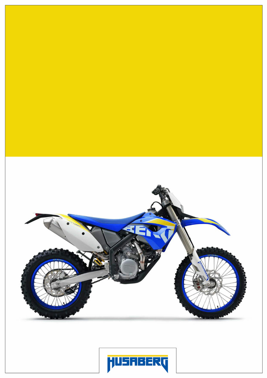
3.1 Chassis number
100345-10
The chassis number is stamped on the right side of the steering head.
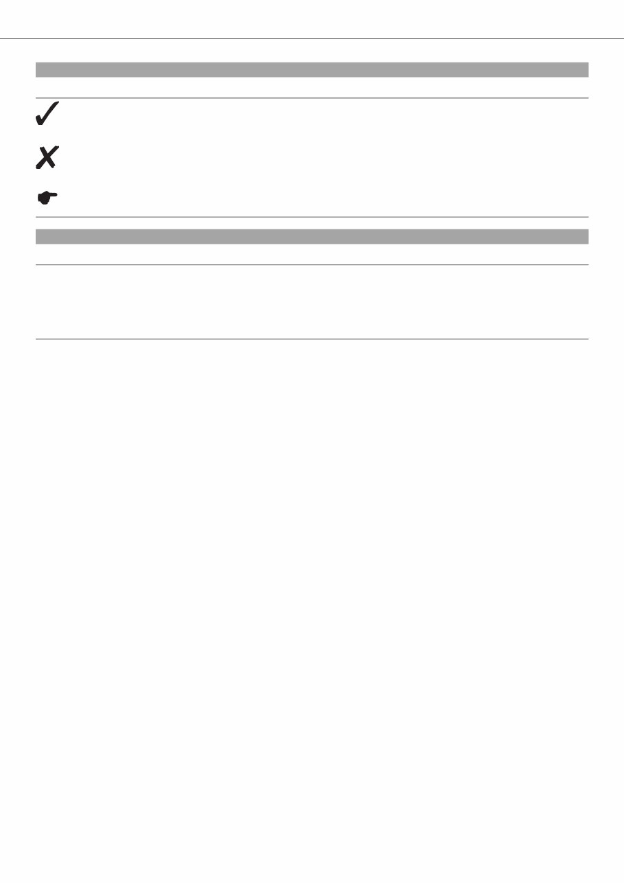
3.2 Type label (FE EU, FE AUS)
100458-10
The type label is fixed to the frame at the front right.
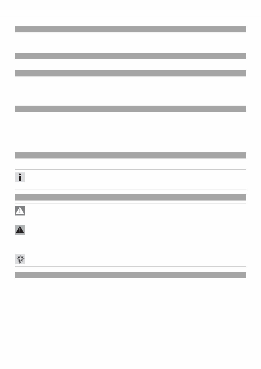
3.3 Type label (FE USA)
100464-10
The type label is fixed to the front of the steering head.
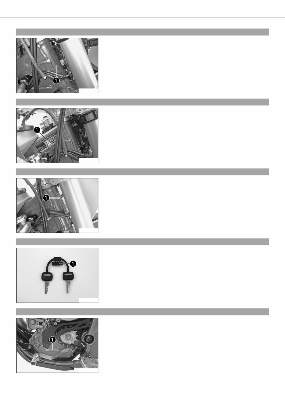
3.4 Key number (FE EU, FE AUS)
500125-10
The key number is stamped on the key strap.
3.5 Engine number
100347-10
The engine number is stamped on the left side of the engine under the engine
sprocket.
LOCATION OF SERIAL NUMBERS 8
3.6 Fork part number
100348-10
The fork part number is stamped on the inner side of the fork stub.
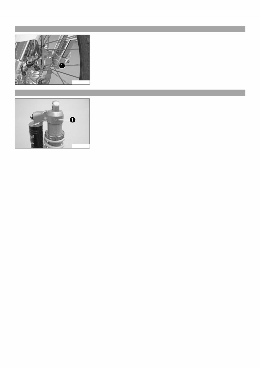
3.7 Shock absorber part number
100419-10
The shock absorber part number is stamped on the upper part of the shock absorber
above the adjusting ring. The shock absorber part number is not visible when the shock
absorber is installed.
You're Reading a Preview
What's Included?
Fast Download Speeds
Offline Viewing
Access Contents & Bookmarks
Full Search Facility
Print one or all pages of your manual
$39.99
Viewed 83 Times Today


Secure transaction
What's Included?
Fast Download Speeds
Offline Viewing
Access Contents & Bookmarks
Full Search Facility
Print one or all pages of your manual
$39.99
This workshop service repair manual covers the HUSABERG FE 450 and FE 570 bikes from 2009 to 2012. It includes the following engine types:
- 449.3 cc 1-cylinder, 4-stroke, water-cooled engine
- 565.5 cc 1-cylinder, 4-stroke, water-cooled engine
The manual contains the following content:
- Safety advice
- Important information
- Serial numbers
- Motorcycle
- Fork, triple clamp
- Handlebar, controls
- Frame & fender
- Shock absorber, swingarm
- Exhaust system
- Air filter system
- Fuel tank, seat, trim
- Mask, fender
- Wheels & tires
- Wiring harness, battery
- Brake system
- Lighting system
- Instruments
- Engine system
- Clutch system
- Water pump
- Cooling system
- Exhaust control
- Lubrication system
- Ignition system
- Electric starter
- Technical data
- Cleaning, care
- Storage system
- Service schedule
- Wiring diagram
- Substances
- Auxiliary substances
- Special tools
This comprehensive manual provides detailed exploded views and step-by-step procedures with pictures and diagrams. It is the same manual used by technicians for vehicle repairs and covers maintenance and servicing. The manual is fully printable, allowing for the selection of specific pages or the entire manual.


