

1985-1997 XR80R / XR100R Service & Repair Manual
What's Included?
Fast Download Speeds
Online & Offline Access
Access PDF Contents & Bookmarks
Full Search Facility
Print one or all pages of your manual

85-97
XRBOR
XR100R
IMPORTANT SAFETY NOTICE
I,.di~.ta " It"'''8 pqssijility of #ft'n /«nDu/ ;IIj,,1')I or dea,. if iutrntiO/U .~ "ot followrd.
CAUTION : IndiCilIU Q possibility 0/ pusong/ inj ury or equipment domoge if IflStfll Cl i oru Q~ flOI /oIlowN.
NOTE : Gives helpful information .
Detailed descri ptions of standard workshop procedures , safety pr i nCiples and service operatIOns are nol included . It is
important to note that th is manual conta ins somlt warnings and cllutions aga i nsl some specific service methods whi ch
could cause PERSONAL INJURY to service personnel or could damage II vehicle or render it unsafe. Please understand
that those warnings c ould not cover all concei\lable ways in whi ch service. whether or not recommended bV Honda
mi ght be done or 01 the possi bly hazltfdous consequences of each conceivable way. nor c ould Honda investigate all
such ways . Anyone using service procedures or too ls, whether 01 not recommended by Honda must satisfy himself
thOloughly that ner ther personal satety nor vehicle satety w ill be jeopardized by the service method or tools selected.
l
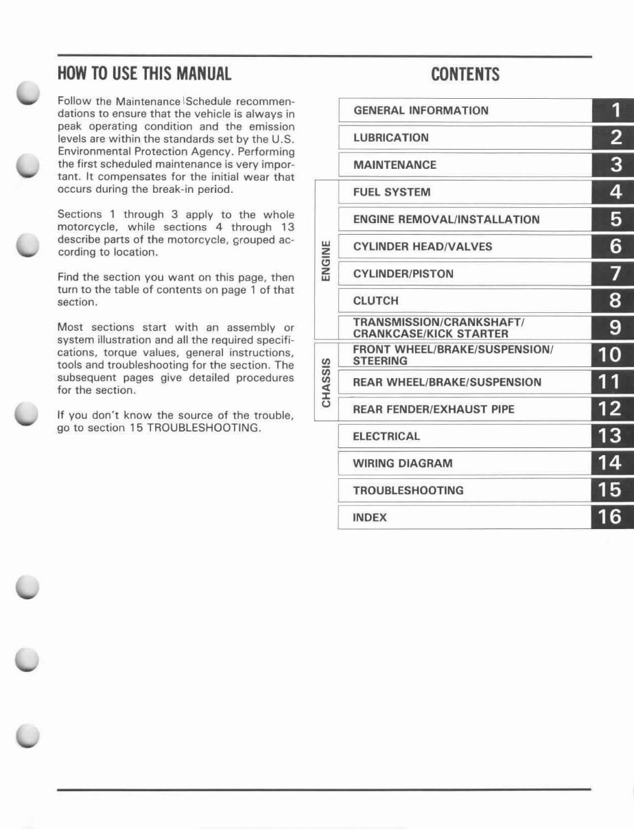
HOW TO USE THIS MANUAL
Follow the Maintenance lSchedule recommen-
dations to ensure that the vehicle is always in
peak operating condition and the emission
le vels are within the standards set by the U.S.
Environmental Protection Agency. Performing
the first scheduled maintenance is very impor-
tant. It compensat es for the initial wear that
occurs during the break-in period.
Sections 1 through 3 apply to the whole
motorcycle, while sections 4 through 13
describe parts of the motorcycle, grouped ac-
cording to location.
Find the section you want on this page, then
turn to the table of contents on page 1 of that
section.
Most sections start with an assembly or
system illustration and all the requir ed specifi-
cations, torque values, general instructions,
tools and troubleshooting for the section. The
subsequent pages give detailed procedures
for the section.
If you don't know the source of the trouble,
go to section 15 TROUBLESHOOTING.
w
Z
"
Z
w
CONTENTS
GENERAL INFORMATION
LUBRICATION
MAINTENANCE
FUEL SYSTEM
ENGINE REMOVAL/INSTALLATION
CYLINDER HEAD/V ALVES
CYLINDER/PISTON
CLUTCH
REAR WHEEl/BRAKE/SUSPENSION
REAR FENDER/ EXHAUST PIPE
ELECTRICAL
WIRING DIAGRAM
TROUBLESHOOTING
INDEX

GENERAL SAFETY
SERVICE RULES
MODEL IDENTIFICATION
SPECIFICATIONS
GENERAL SAFETY
1 -1
1 - 1
1-2
1-3
IJ 'hI> .. 1I_vin,. mu st M fll nning /0 (10 some work . make S life the
artN ;s w('/f· ref/tilaleel. Nt'!'/'( run the engine in a closed area.
The exhaust conlains poi so nous carbol/ mOl/oxide gas, IIIOf
may CUllSt' loss of consciollsnen ami lead to death.
Gasoline is atremei)' /lom",ablt· ami is t'xplal;\"( ' lI11der enlDill
conditions. Do nor smoke Of allow flam es or .fporh in YOllr
work areo. Of where gasoline is S lored.
CAUTION
Used engine oil moy cOllse skill cancer if repeatedly /e/I in COI/ ·
/ac/ with Ihe skin for pro/allgell periods. Allhough (his j{
Im/ike'y IInless YOII handle used oil all a daily basis, il is slill
adl'isable /0 Ihoroughly K'asl! your hands willi soap and \Wller
as soon as possible afler hondfing IIsed oil.
SERVICE RULES
1. GENERAL INFORMATION
TORQUE VALUES
TOOLS
CABLE & HARNESS ROUTING
iii
1 -5
1-6
1 -7
Inhaled asbf!Slos fibers hal 't' been lound (f) C(lIlte re spirOWf)'
(liseaJ't' and canct'r, Nt'I'er li St' (III air host' or Ilf)' hllll'h 10 dean
brak(' as "st'mblies. Uu OS IIA .apprOL'ed l'aC/lllm cleaner IIr af·
lemate method appral't'd h}' OS IIA clesilflled 10 "'inimht' Ih('
ho~ard callst'd by airbornt' asbestos fibers,
Use genuine HONDA or HONDA- recommended parts and lubricants or their eqUivalents Parts that don 't meet
HONDA's design speCifications may damage 10 Ihe vehicle
2. Use the special tools deSigned for thiS product to aVOid damage and incorrect assembly.
3. Use only melnc tools when servICing the vehicle. Metnc bolts. nuts, and screws are no t Interchangeable With English
fasteners
4. Instal! new gaskets. O.rings. cotter pins, and lock plates when reassembling
5 When tightening bolts or nuts. begin With the larger -diameter or Inner bolts first Then tighten to the specified IOrque
diagonally in t·5 s.teps. unless a particular sequence IS specified
6 Clean parts 10 non-flammable or high flash pomt solvent upon disassembly lubflcate any sliding surfaces before
reassembly
7. After reassembly. check all parts for proper InstallatIOn and operation
8 Route all w ires as shown on pages '·7 through 1- 11 Cable and Harness Routmg
1-1
GENERAL INFORMATION
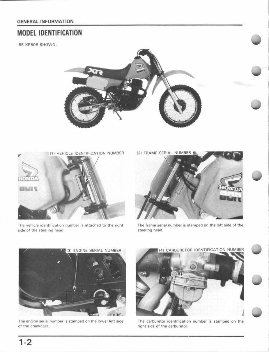
MOOEL IDENTIFICATION
' 85 XR80A SHOWN :
(1) VEHICLE IDENTIFICATION NUMBER
The vehicle identification number is attached to the right
side of the steering head.
The engine serial number is stamped on the lower left side
of the crankcase.
1-2
(2) FRAME
The frame serial number is stamped on the left side of the
steering head.
The carburetor identification number is stamped on the
right side of the carbureto r.
GENERAL INFORMATION
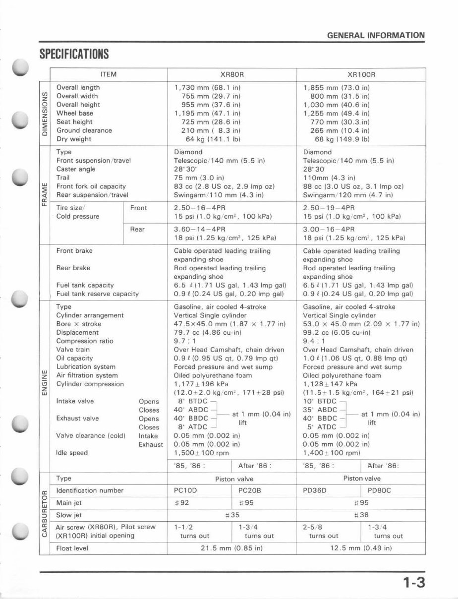
SPECIFICATIONS
ITEM XABOR XR1QQR
Overall length 1, 730 mm (68.1 in) 1,855 rnm (73.0 in)
<I>
Overall wi dth 755 mm (29 .7 in) 800 mm (3 1 .5 in)
Z
0 Overall height 955 mm (37 . 6 in) 1, 030 mm ( 40 .6 in )
in
Wheel base 1, 195 mm (47 . 1 in ) 1,255 mm (49 .4 in )
z
w
Seat height 725 mm (28 .6 in) 770 mm (30 . 3. in)
"
0
Ground clearance 210 mm ( 8.3 in) 265 mm (10.4 in )
Dry weight 64kg (141 . 1Ib) 68 kg (149 .9 )b l
Type Diamond Diamond
Front suspension/ travel Telescopic / 140 mm (5.5 in ) Telescopic f 140 mm (5.5 in )
Caster angle 28 · 30' 28 · 30'
Trail 75 mm (3.0 in) 110mm (4 .3 in)
w
Front fork. oil capacity 83 cc (2 .8 US OZ , 2 .9 Imp ezl 88 cc (3.0 US OZ , 3.1 Imp ez l
"
"
Rear suspension i travel Swingarm / l1Q rnm (4 . 3 in) Swingarm / 12Q mm (4 .7 in)
'"
~
Tire size l Front 2. S0 - 16 - 4PR 2. 50 - 19 - 4PR
Cold pressure 15 psi (1.0 kg / cm
2
, 100 kPa ) 15 psi ( 1.0 kg cm !, 100 kPa )
Rear 3, 60 - 14 - 4PR 3. 00-16-4PR
18 psi (1. 25 kg /cm~, 125 kPa) 18psi (1. 25kgcrr.
2
,125kPa )
Front brake Cable operated leading trailing Cable operated leading trailing
expanding shoe expanding shoe
Rear brake Rod operated leading trailing Rod operated leading trailing
expanding shoe expanding shoe
Fuel tank capacity 6.5 t( 1.71 US gal, 1,43 Imp ga l) 6 .5 1( 1. 71 USgal,l,43Impgal )
Fuel tank reserve capacity 0.9 t (0.24 US gal, 0.20 Imp gal) 0 .9 t (0 . 24 US gal , 0.20 Imp gal)
Type Gasoline, air cooled 4-stroke Gasoline, air cooled 4-stroke
Cylinder arrangement Vertical Single cylinder Vertical Single cylinder
Bore x stroke 47 .5x 45 .0 mm (1 . 87 x 1. 77 in) 53 .0 x 45 .0 mm (2 . 09 X 1 . 77 in )
Displacement 79 .7 cc (4 . 86 cu -in) 99 ,2 cc (6 . 05 cu-in)
Compression ratio 9. 7: 1 9.4 : 1
Valve train Over Head Camshaft , chain driven Over Head Camshaft , chain driven
Oil capacity 0 .9 t (0 . 95 US qt. 0.79 Imp qt) 1.0 t (1.06 US qt , 0.88 Imp qt )
Lubrication system Forced pressure and wet sump Forced pressure and wet sump
w
Air filtration system Oiled polyurethane foam Oiled polyu rethane foam
z
'-"
Cylinder compression l, l77 ± 196 kPa 1, 128 ± 147 kPa
Z
(12 ,O± 2 .0 kg / cm
2
, 171 ± 28 psi) (11 , 5 ± 1 , 5 kg cm
2
, 164 ± 21 psi) w
Intake valve Opens 8" BTDC 10" BTDC
Closes
40' ABOC }- . 35 ' ABDC }- .
Exhaust valve Opens
40" BBDC at ., mm ( 0.04 In ) 40" BBDC _ at ., mm ( 0.04 m)
Closes
8" ATDC lift 5" ATDC lift
Valve clearance (cold) Intake 0. 05 mm (0 .002 in) 0.05 mm ( 0.002 in )
Exhaust 0. 05 mm (0 . 002 in) 0,05 mm (0 . 002 in)
Idle speed 1 ,500 ± 100 rpm 1, 400 ± 100rpm)
' 85, ' 86: After ' 86 : ' 85 , '86 : After ' 86 :
Type Piston valve Piston valve
'"
Identification number PC10D PC20e PD36D P080C
0
tu
Main jet .92 095 :: 95
'"
::> Slow jet :: 35 :: 38
"
'"
Air screw (XR80R), Pilot screw 1- 1/ 2 1-3 4 2-5/8 1-3 4
"
u (XA 1 OOR) initial opening turns out turns out turns out turns out
Float level 21.5 mm (0 . 85 in) 12 5 mm (0.49 in )
1-3
GENERAL INFORMATION
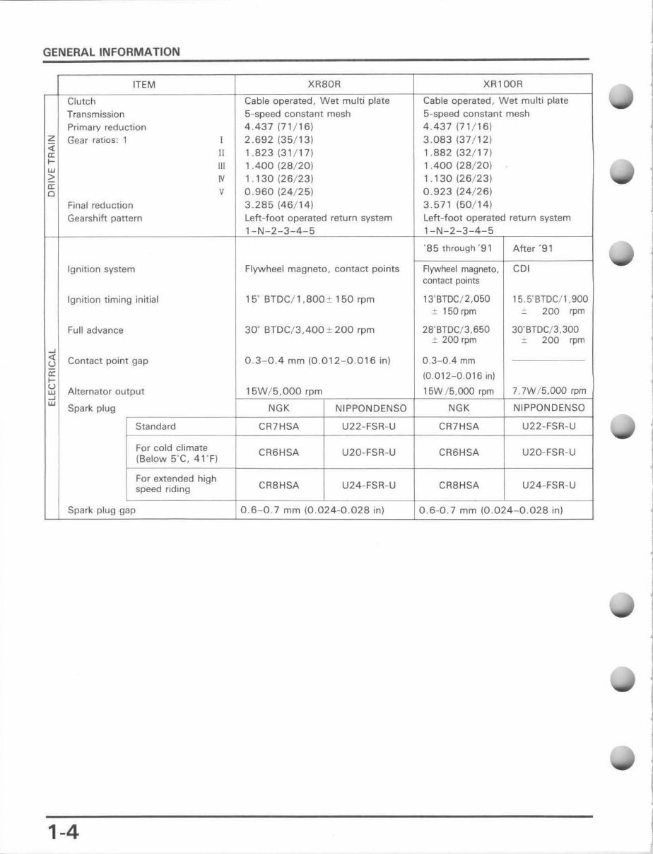
ITEM XR80R XR1QOR
Clutch Cable operated, Wet multi pl ate Cable operated, Wet multi plate
Transmission 5-speed constant mesh 5-speed constant mesh
Primary reduction 4.437 (71 / 16) 4.437 P1 / 16)
z
Gear ratios: 1 1 2. 692 (35/13) 3.083 (37 / 12)
<l
II 1.823 (3 1/ 17) 1. 882 (32/17)
'"
r-
III 1.400 (28/20) 1.400 (28 / 20)
w
"
N 1. 130 (26/23) 1. , 30 (26/23)
'"
V 0.960 (24/ 25) 0. 923 (24/ 26)
"
Final reduction 3.285 (46/ 14) 3.571 (50/ 14)
Gearshift pattern Left-foot operated return system Left- f oot operated return system
l-N-1-3-4-5 l-N-Z-3-4-5
'85 through '91 After '91
Ignition system Flywheel magneto. contact points Flywheel magneto, CDl
contact points
Ignition timing initial IS" BTDC / l,800 ± 150 rpm 13' STDC / Z,050 15.5"BTDCj l , 900
J: 150 rpm ± 200 'pm
Full advance 30' BTDC/ 3.400 ± 200 rpm 28' BTDC/ 3,650 30' STDC/3, 300
± 200 rpm ± 200 'pm
~
"
Contact point gap O.3~O.4 mm (0. 012-0 . 016 in) 0. 3-0.4 mm
S1
'"
(0.012-0.016 in)
r-
u
Alternator output 15W/ 5,OOO rpm 15W / 5,000 rpm 7. 7W / 5,000 rpm
w
~
w
Spark plug NGK NIPPONDENSO NGK NIPPONDENSO
Standard CR7HSA U22-FSR-U CR7HSA U22-FSA-U
For cold climate
CR6HSA U20-FSR-U CA6HSA U20-FSR-U
(Below S' C, 4, ' F)
For e)(l:ended high
CR8HSA U24-FSR-U CR8HSA U24-FSA-U
speed riding
Spark plug gap 0. 6-0 .7 mm (0.024-0.028 in) 0. 6-0.7 mm (0.024-0.028 in)
1-4
GENERAL INFORMATION
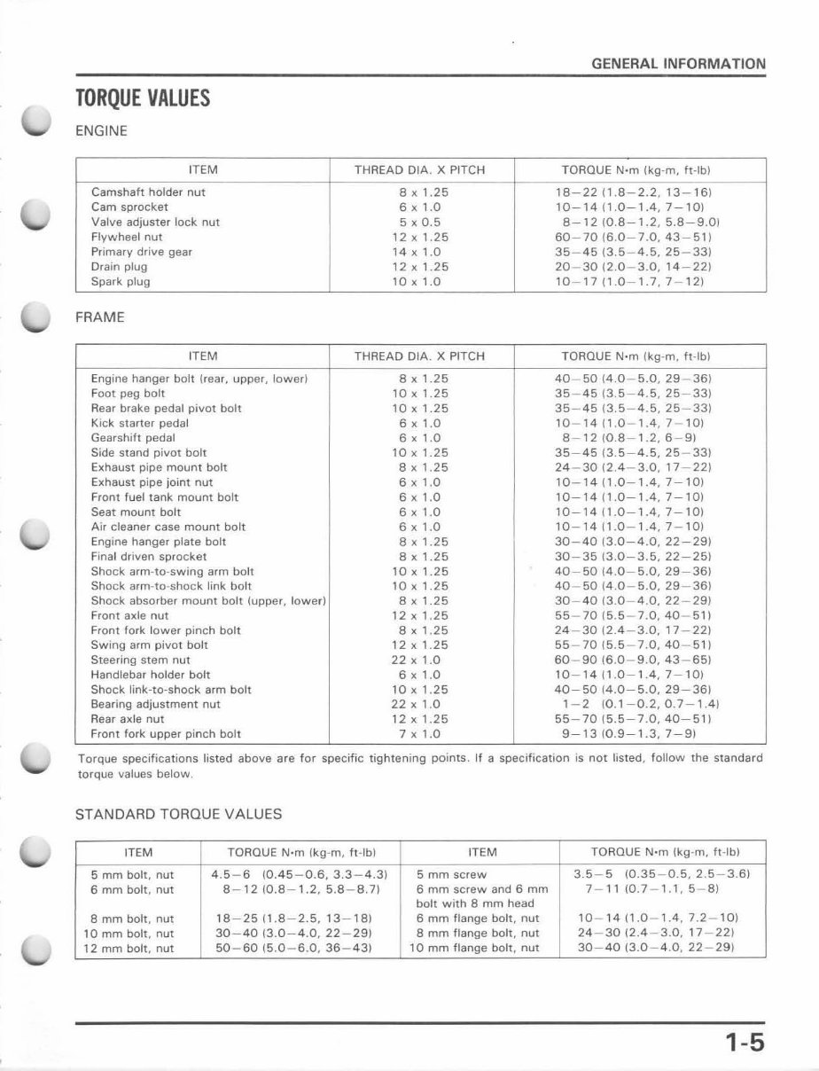
TORQUE VALUES
ENGINE
ITEM THREAD OIA. X PITCH TORQUE N·m ~kg·m, ft-lbJ
Camshaft holder nut 8 x 1.25 18 - 22 n.B - Z.2. 13 -1 6)
Cam sprocket 6 x 1.0 10-14 (1.0-1.4, 7-10)
Valve adjuster lock nut 5 x 0.5 8-12 (Q.8-1.2, 5.8-9.0)
Flywheel nut 12 x 1.25 60 - 70 (6.0-7.0. 43-51)
Primary drive gear '4 x 1.0 35-45 (3.5-4.5, 25 -3 3)
Drain plug 12 x 1.25 20-30 (2.0-3.0,14-22)
Spark plug 10 x 1.0 10 - 17 n.D-1.7, 7- 12)
FRAME
ITEM THREAD OIA. X PITCH TORQUE N·m (kg-m. ft -I bl
Engine hanger bolt (rear, upper, lower) 8 , 1 .25 40-5014.0 - 5.0,29 - 36)
Foot peg bolt 10 x 1.25 35 - 45 (3.5 - 4.5, 25 - 33)
Rear brake pedal pivot bolt 10xl.25 35 - 45 (3.5- 4 .5, 25-33)
Kick starter pedal 6 x 1.0 10 - 14 (1.0 - 1.4. 7-10)
Gearshift pedal 6 x 1.0 8-12 (0.8-1.2,6-9)
Side stand pivot bolt tOxt.25 35-45 (3.5-4.S, 25 - 33)
Exhaust pipe mount bolt a x , .25 24 - 30 (2.4-3.0,17-22)
Exhaust pipe joint nut 6 x '.0 10 - 14 (1.0-1.4, 7-10)
Front fuel tank mount bolt 6 x '.0
10-14 (1.0- 1.4, 7-lm
Seat mount bolt 6 x 1.0 10-14 (1.0-1.4, 7-10)
Air cleaner case mount bolt 6 x '.0 10 - 14 (1.0 - 1.4, 7- 10)
Engine hanger plate bolt 8 x , .25 30 - 40 (3.0-4.0, 22 - 29)
Final driven sprocket 8 x 1.25 30 - 35 (3.0-3.S, 22 - 251
Shock arm-to-swing arm bolt 10 x 1.25 40 - S0 (4 .0-5.0, 29-36)
Shock arm-to-shock link bolt 10 x 1 .25 40 - S0 (4.0 - 5.0, 29 - 36)
Shock absorber mount bolt (upper, lowed 8, 1 .25 30 - 40 (3.0 - 4.0,22 - 29)
Front axle nut 12 x , .25 55-70 (5.5 -7 .0, 40-51)
Front fork lower pinch bolt 8 , 1 .25 24-30 (2.4-3.0,17-22)
Swing arm pivot bolt 12x1.25 55 - 70 (5.5- 7 .0, 40- 51)
Steering stem nut 22 x 1.0 60 - 90 (6 .0 - 9.0, 43 - 65)
Handlebar holder bolt 6 x 1.0 10-14 (1.0-1.4, 7-10)
Shock link-to-shock arm bolt 10 x 1.25 40-50 (4.0 -5.0, 29-36)
Bearing adjustment nut 22 x 1.0 1- 2 (0.1-0.2,0.7-1.4)
Rear axle nut 12 x 1.25 55 - 70 (5.5-7.0, 40-51)
Front fork upper pinch bolt 7 x 1.0 9-1310.9-1.3,7-91
Torque specifications listed above are for specific tightening points. If a specification is not listed, follow the standard
torque values below.
STANDARD TORQUE VALUES
ITEM TORQUE N·m (kg-m, ft -Ib) ITEM TORQUE N·m ( kg -m, ft-Ib)
5 mm bolt, nut 4.S - 6 (0.45-0.6, 3.3 - 4.3) 5 mm screw 3.5 - 5 (0.35 - 0.S. 2.5 - 3.6)
6 mm bolt. nut 8-12 (0.8-1.2, 5.8 - 8.71 6 mm screw and 6 mm 7- 11 m.7 - 1.1, 5-8)
b olt With 8 mm head
8 mm bolt, nut 18-2511.8-2.5,13-18) 6 mm flange bolt, nut 10 - 14 (1.0 -1.4, 7.2-10)
10 mm bolt, nut 30 - 40 (3. 0-4.0, 22 - 29) 8 mm flange bolt, nut 24-30 (2.4-3.0,17 - 22)
t 2 mm bolt, nut 50 - 60 (5. 0 - 6.0, 36 - 43) 10 mm flange bolt , nut 30 - 40 (3.0 - 4.0,22 - 291
1-5
GENERAL INFORMATION
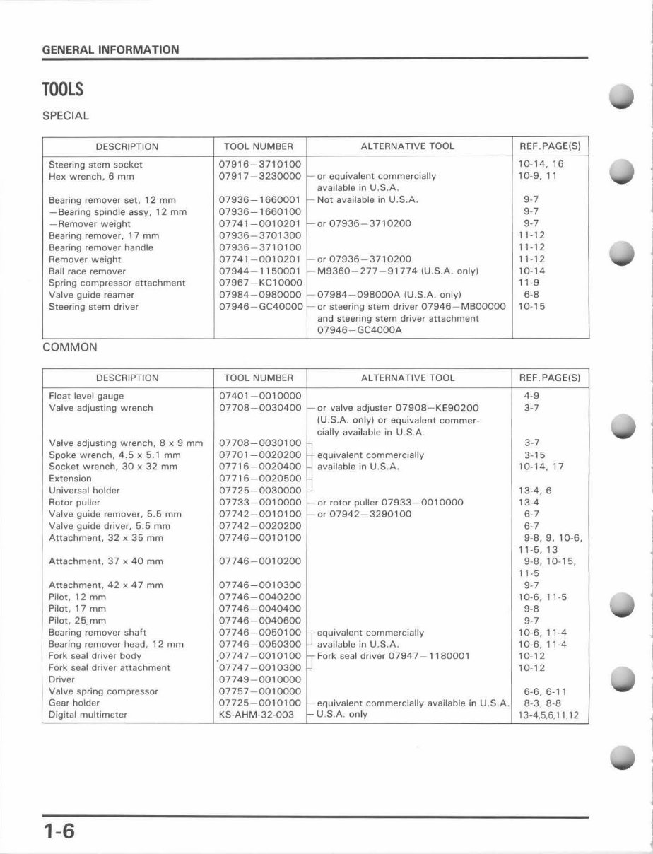
TOOLS
SPEC IAL
DESCRIPTION TOOL NUMBER AL TEANATIVE TOOL REF , PAG E(S)
Steering stem socket 07916 - 3710100 10- 14,16
Hex wrench, 6 mm 07917 - 3230000 - or equivalent commerciallv 10-9, 11
available in U.S.A .
Bearing remover set, 12 mm 07936-1660001 Not available in U.S.A . 9~ 7
- Bearing spindle assy, 12 mm 07936 - 1660100 9~7
- Remover weight 07741-0010201 - or 07936 - 3710200 9~7
Bearing remover, 17 mm 07936 - 3701300 , ,- 12
Bearing remover handle 07936 - 3710100 11 -1 2
Remover weight 07741 - 0010201 or 07936 - 3710200 11-12
Ball race remove r 07944 - 1150001 M9360 - 277 - 91774 IU.S.A. onlyl 10- 14
Spring compressor attachment 07967 - KC1OOOO 11 -9
Valve guide reamer 07984 - 0980000 0798 4- 098000A (U . S.A. only) 6~B
Steering stem driver 07946 - GC40000 - or steering stem driver 07946 - MBOOOOO 10- 15
and steering stem driver attachment
07946-GC4000A
COMMON
DESCRIPTION TOOL NUMBER ALTERNATIVE TOOL REF . PAGE(S)
Float level gauge 07401 - 0010000 4~9
Valve adjusting wrench 07708-0030400 - or valve adjuster 07908 -KE90200 3-7
(U .S.A. only) or equivalent commer-
cially available in U.S.A.
Valve adjusting wrench. 8 x 9 mm 07708-0030100 3-7
Spoke wrench , 4.5 x 5.1 mm 07701 -0020200 equivalent commerc ially 3-15
Socket w rench, 30 x 32 mm 07716 - 0020400 available in U.S.A. 10- 14,17
Extension 07716 - 0020500
Universal holder 07725 - 0030000 13-4, 6
Rotor puller 07733 - 0010000 or rotor puller 07933 - 0010000 13-4
Valve guide remover, 5.5 mm 07742-0010100 or 07942-3290100 6~ 7
Valve guide driver, 5.5 mm 07742 - 0020200 6~ 7
Attachment. 32 x 35 mm 07746 - 0010100 9-8,9, 10-6,
11 -5 , 13
Attachment, 37 x 40 mm 07746-0010200 9-8, 10- 15 .
11 -5
Attachment, 42 x 47 mm 07746-0010300 9~ 7
Pilot, 12 mm 07746-0040200 10-6, 11 -5
Pi lot, 17 mm 07746 - 0040400 9~B
Pi lot , 25. mm 07746 - 00 40600 9~7
Bearing remover shaft 07746 - 0050100 equivalent commercially 10-6, 11 -4
8earing remover head, 12mm 07746-0050300 available in U.S.A . 10- 6,11 -4
Fork seal driver body 07747 - 0010100 Fork seal driver 07947 - 1180001 10-12
Fork seal driver attachment 07747 - 0010300 10-12
Driver 07749 - 0010000
Valve spring compressor 07757-0010000 6- 6,6-11
Gear holder 07725 - 0010100 equivalent commercially available in U.S.A. 8-3,8-8
Digital multimeter KS-AHM-32 -003 U.S.A. on ly 13-4,5,6, 11 , 12
1-6
You're Reading a Preview
What's Included?
Fast Download Speeds
Online & Offline Access
Access PDF Contents & Bookmarks
Full Search Facility
Print one or all pages of your manual
$31.99
Viewed 11 Times Today


Secure transaction
What's Included?
Fast Download Speeds
Online & Offline Access
Access PDF Contents & Bookmarks
Full Search Facility
Print one or all pages of your manual
$31.99
Get your hands on a comprehensive repair manual for the 1985-1997 Honda XR80R and Honda XR100R four-stroke bikes. This manual covers everything from complete tear down and rebuild, to pictures and part diagrams, torque specs, maintenance, troubleshooting, and more. With 168 pages, it's a valuable resource for both professional mechanics and DIY enthusiasts.
This manual comes with clickable chapters and is searchable, making it easy to find the information you need. It also has no restrictions on printing, saving, etc.
- Complete tear down and rebuild
- Pictures and part diagrams
- Torque specs
- Maintenance procedures
- Troubleshooting guidance
- Clickable chapters
- Searchable content
- No restrictions on printing or saving


