

Honda XR 650R service manual
What's Included?
Fast Download Speeds
Online & Offline Access
Access PDF Contents & Bookmarks
Full Search Facility
Print one or all pages of your manual
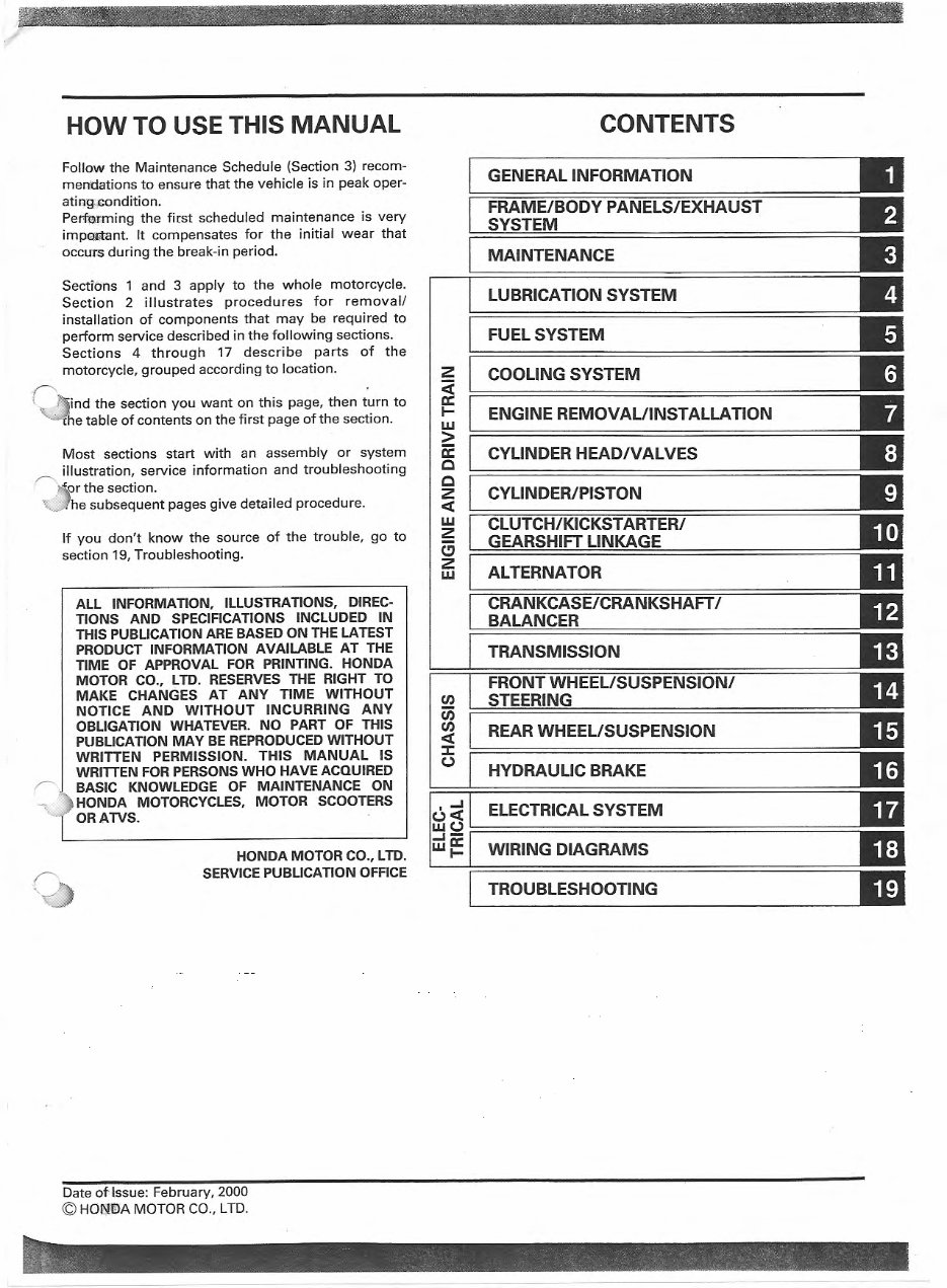
HOW TO USE THIS MANUAL
Follow the Maintenance Schedule (Section 3) recom-
mendations to ensure that the vehicle is in peak oper-
atill'g .condition.
Perfurming the first scheduled maintenance is very
impOJitant. It compensates for the initial wear that
occu.r.s during the break-in period.
Sections 1 and 3 apply to the whole motorcycle.
Section 2 illustrates procedures for remova l/
installation of components that may be required to
perform service described in the following sections.
Sections 4 through 17 describe parts of the
motorcycle, grouped according to location.
!' . .
! ._ 7'-ind the section you want on this page, then turn to
' -1he table of contents on the first page of the section.
Most sections start with an assembly or system
illustration, service information and troubleshooting
,---..,. " or the section.
~'~~e subsequent pages give detailed procedure.
If you don't know the source of the trouble, go to
section 19, Troubleshooting.
ALL INFORMATION, ILLUSTRATIONS, DIREC-
TIONS AND SPECIFICATIONS INCLUDED IN
THIS PUBLICATION ARE BASED ON THE LATEST
PRODUCT INFORMATION AVAILABLE AT THE
TIME OF APPROVAL FOR PRINTING. HONDA
MOTOR CO., LTD. RESERVES THE RIGHT TO
MAKE CHANGES AT ANY TIME WITHOUT
NOTICE AND WITHOUT INCURRING ANY
OBLIGATION WHATEVER. NO PART OF THIS
PUBLICATION MAY BE REPRODUCED WITHOUT
WRITTEN PERMISSION. THIS MANUAL IS
WRITTEN FOR PERSONS WHO HAVE ACQUIRED
r' BASIC KNOWLEDGE OF MAINTENANCE ON
) HONDA MOTORCYCLES, MOTOR SCOOTERS
OR ATVS. ·
HONDA MOTOR CO., LTD.
0
SERVICE PUBLICATION OFFICE
Date otlssue: February, 2000
© HON'IDA MOTOR CO., LTD.
z
<(
a:
1-
w
>
a:
c
c
z
<(
w
~
(!)
z
w
(J)
u;
(J)
<(
::c
(.)
I -I
CONTENTS
GENERAL INFORMATION
FRAME/BODY PANELS/EXHAUST
SYSTEM
MAINTENANCE
LUBRICATION SYSTEM
FUEL SYSTEM
COOLING SYSTEM
ENGINE REMOVAUINSTALLA TION
CYLINDER HEAD/VALVES
CYLINDER/PISTON
CLUTCH/KICKSTARTER/
GEARSHIFT LINKAGE
ALTERNATOR
CRANKCASE/CRANKSHAFT I
BALANCER
TRANSMISSION
FRONT WHEEUSUSPENSION/
STEERING
REAR WHEEL/SUSPENSION
HYDRAULIC BRAKE
ELECTRICAL SYSTEM
(.)<(
we.>---======================================
_,_.-
w~ WIRING DIAGRAMS
TROUBLESHOOTING
r
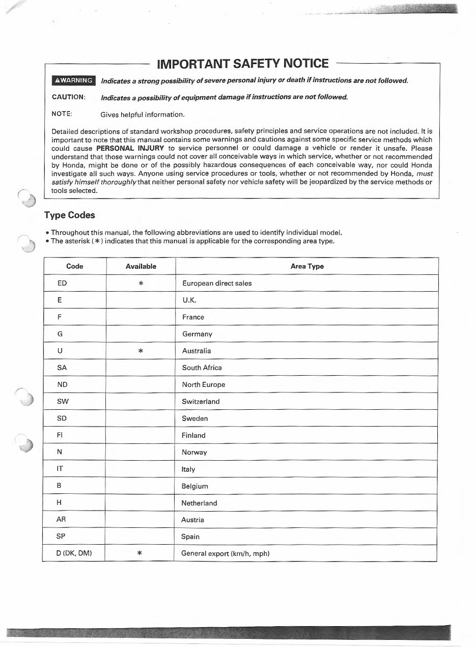
IMPORTANT SAFETY NOTICE
fN'?f.1;iUH9 Indicates a strong possibility of severe personal injury or death if instructions are not followed.
CAUTION: Indicates a possibility of equipment damage if instructions are not followed.
NOTE:
Gives helpful information.
Detailed descriptions of standard workshop procedures, safety principles and service operations are not included. It is
important to note that this manual contains some warnings and cautions against some specific service methods which
could cause PERSONAL INJURY to service personnel or could damage a vehicle or render it unsafe. Please
understand that those warnings could not cover all conceivable ways in which service, whether or not recommended
by Honda, might be done or of the possibly hazardous consequences of each conceivable way, nor could Honda
investigate all such ways. Anyone using service procedures or tools, whether or not recommended by Honda, must
satisfy himself thoroughly th at neither personal safety nor vehicle safety will be jeopardized by the service methods or
tools selected.
Type Codes
•Throughout this manual, the following abbreviations are used to identify individual model.
•The asterisk (*)indicates that this manual is applicable for the corresponding area type.
Code Available Area Type
ED
*
European direct sales
E U.K.
F France
G Germany
u
*
Australia
SA South Africa
ND North Europe
SW Switzerland
SD Sweden
Fl Finland
N Norway
IT Italy
B Belgium
H Netherland
AR Austria
SP Spain
D(DK, DM)
*
General export (km/h, mph)
r
')
(
.......... ~·~ : ? ., "?SrJUtiWt! ; l ..
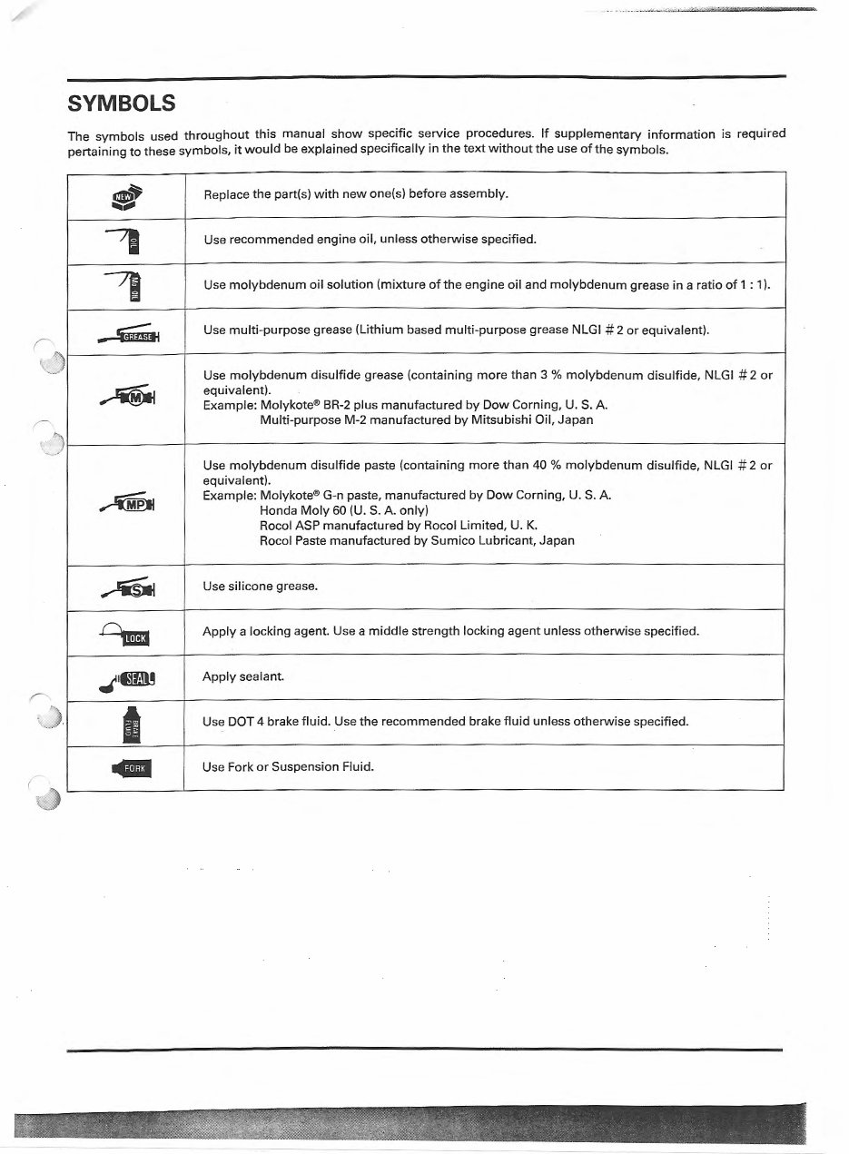
SYMBOLS
The symbols used throughout this manual show specific service procedures. If supplementary information is required
pertaining to these symbols, it would be expl ained specifically in the text without the use of the symbols.
~
e
Replace the part(s) with new one(s) before assembly .
,
Use recommended engine oil, unless otherwise specif ied.
,
Use molybdenum oil soluti on (mixture of the engin e oil and mol ybd enum grease in a ratio of 1 : 1).
_..ww
Use multi-purpose grease (Lithium based multi -purpose grease NLGI # 2 or equivalent).
Use molybdenum disulfide grease (containing more than 3 % molybdenum disulfide, NLGI # 2 or
~
equivalent).
Example: Molykote ® BR-2 plus manufactured by Dow Corning, U. S. A
Multi- purpose M-2 manufactured by Mitsubishi Oil, Japan
Use molybdenum disulfide pa ste (containing more than 40 % molybdenum disulfide, NLGI # 2 or
equivalent).
~
Example: Molykote® G-n paste, manufactured by Dow Corning, U.S. A
Honda Moly 60 (U. S. A only)
Rocol ASP manufactured by Rocol Limited, U. K.
Rocol Paste manufactured by Sumico Lubri ca nt, Japan
~
Use silicone grease.
cw
Apply a locking agent. Use a middl e strength locking agent unless oth erwise specified.
.t'mD!
Apply sealant.
I
Use DOT 4 brake fluid. Use the recomm ended brake flu id unless otherwise specified .
...
Use Fork or Suspension Fluid.
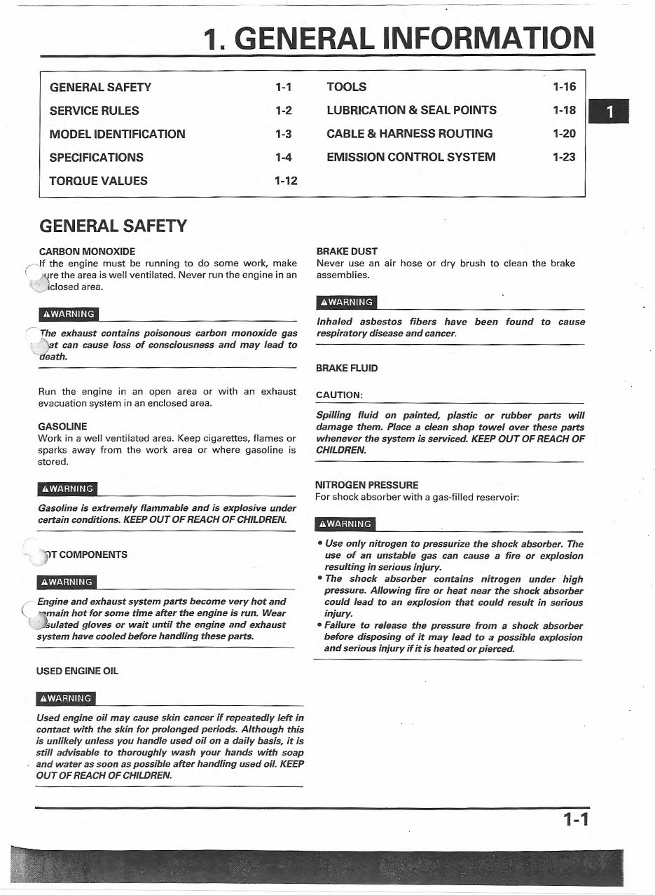
1. GENERAL INFORMATION
GENERAL SAFETY 1-1
SERVICE RULES 1-2
MODEL IDENTIFICATION 1-3
SPECIFICATIONS 1-4
TORQUE VALUES 1-12
GENERAL SAFETY
CARBON MONOXIDE
r lf the engine must be running to do some work, make
~re the area is well vent ilated. Never run the engine in an
"-· Jclosed area.
r The exhaust contains poisonous carbon monoxide gas
· "\.at can cause loss of consciousness and may lead to
' death.
Run the eng ine in an open area or with an exhaust
evacuation system in an enclosed area.
GASOLINE
Work in a well ventilated area. Keep cigarettes, flames or
sparks away from the work area or where gasoline is
stored.
Gasoline is extremely flammable and is explosive under
certain conditions. KEEP OUT OF REACH OF CHILDREN.
T COMPONENTS
(
Engine and exhaust system parts become very hot and
" "mai n hot for some time after the engine is run. Wear
{ ) sulated gloves or wait until the engine and exhaust
system have cooled before handling these p art s.
USED ENGINE OIL
Used engine oil may cause ski n cancer if repeatedly left in
contact with the skin for prolonged periods. Although this
is unlikely unless you handle used oil on a daily basis, it is
still advisable to thoroughly wash your hands with soap
and water as soon as possible after handling used oil. KEEP
OUT OF REACH OF CHILDREN.
TOOLS
LUBRICATION & SEAL POINTS
CABLE & HARNESS ROUTING
EMISSION CONTROL SYSTEM
BRAKE DUST
1-16
1- 18.
1-20
1-23
Never use an air hose or dry brush to clean the brake
assemblies.
Inhaled asbestos fibers have been found to cause
respiratory disease and cancer.
BRAKE FLUID
CAUTION:
Spilling fluid on painted, plastic or rubber parts will
damage them. Place a clean shop towel over these parts
whenever the system is serviced. KEEP OUT OF REACH OF
CHILDREN.
NITROGEN PRESSURE
For shock absorber with a gas-filled reservoir:
• Use only nitrogen to pressurize the shock absorber. The
use of an unstable gas can cause a fire or explosion
resulting in serious injury.
• The shock absorber contains nitrogen under high
pressure. Allowing fire or heat near the shock absorber
could lead to an explosion that could result in serious
injury .
• Failure to release the pressure from a shock absorber
before disposing of it may lead to a possible explosion
and serious injury if it is heated or pierced.
1-1
GENERAL INFORMATION
COOLANT
Under some conditions, the ethylene glycol in engine coolant
is combustible and its flame is not visible. If the ethylene
glycol does ignite, you will not see any flame, but you can be
burned.
•Avoid spilling engine coolant on the exhaust system or
engine parts. They may be hot enough to cause the coolant
to ignite and burn without a visible flame.
• Coolant (ethylene glycol} can cause some skin irritation and
is poisonous if swallowed. KEEP OUT OF REACH OF
CHILDREN.
• Do not remove the radiator cap when the engine is hot.
The coolant is under pressure and could scald you.
( ~UTION:
' /
' Using coolant with silicate corrosion inhibitors may cause
premature wear of water pump seals or blockage of radiator
passages.
- Using tap water may cause engine damage.
l l
· .._,/
If it contacts your skin, wash the affected areas immediately
with soap and water. If it contacts your eyes, flush them
thoroughly with fresh water and get immediate medical
attention. If it is swallowed, the victim must be forced to vomit,
then rinse mouth and throat with fresh water before obtaining
medical attetion. Because of these dangers, always keep from
the reach of children. Recycle used coolant in an ecologically
correct manner.
SERVICE RULES
1. Use genuine HONDA or HONDA-recommended parts and lubricants or their equivalents. Parts that don't meet HONDA's
design specifications may cause damage to the motorcycle.
2. Use the special tools designed for this product to avoid damage and incorrect assembly.
?· Use only metric tools when servicing the motorcycle. Metric bolts, nuts and screws are not interchangeable with English
'lsteners.
· ..... nstall new gaskets, 0-rings, cotter pins, and lock plates when reassembling. ·
5. When tightening bolts or nuts, begin with the larger diameter or inner bolt first. Then tighten to the specified torque
diagonally in incremental steps unless a particular sequence is specified.
6. Clean parts in cleaning solvent upon disassembly. Lubricate any sliding surfaces before reassembly.
r-ie-tt er reassembly, check all parts for proper installation and operation.
:.: _) oute all electrical wires as show on pages 1-20 through 1-22, Cable and Harness Routing.
1-2
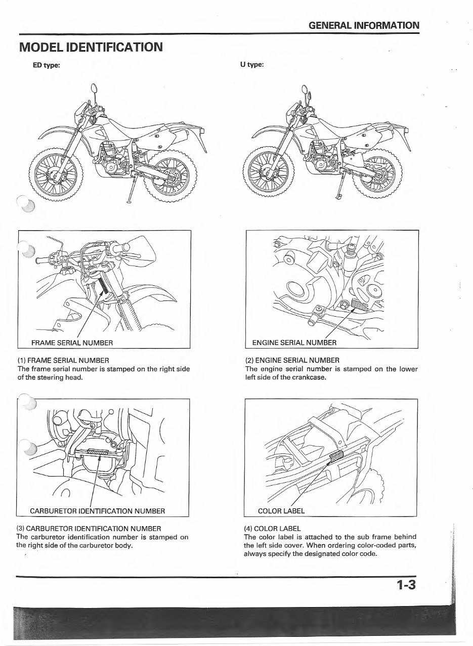
MODEL IDENTIFICATION
ED type:
FRAME SERIAL NUMBER
(1) FRAME SERIAL NUMBER
The frame serial number is stamped on the right side
of the steering head.
CARBURETOR IDENTIFICATION NUMBER
(3) CARBURETOR IDENTIFICATION NUMBER
The carburetor identificat ion number is stamped on
the right side of the carburetor body.
I
GENERAL INFORMATION
Utype:
(2) ENGINE SERIAL NUMBER
The engine serial number is stamped on the lower
left side of the crankcase.
COLOR LABEL
(4) COLOR LABEL
The color label is attached to the sub frame behind
the left side cover. When ordering color-coded parts,
always specify the designated color code.
1-3
GENERAL INFORMATION
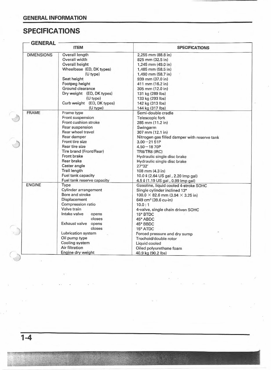
SPECIFICATIONS
-GENERAL
DIMENSIONS
ITEM
Overall length
Overall width
Overall height
Wheelbase (ED, DK types)
(U type)
Seat height
Footpeg height
Ground clearance
Dry weight (ED, DK types)
(U type)
Curb weight (ED, DK types)
(U type)
,,.- FRAME Frame type
~ )
r
,)
ENGINE
r
.,)
(
~)
1-4
Front suspension
Front cushion stroke
Rear suspension
Rear wheel travel
Rear damper
Front tire size
Rear tire size
Tire brand (Front/Rear)
Front brake
Rear brake
Caster angle
Trail length
Fuel tank capacity
Fuel tank reserve capacity
Type
Cylinder arrangement
Bore and stroke
Displacement
Compression ratio
Valve train ·
Intake valve opens
closes
Exhaust valve opens
closes
Lubrication system
Oil pump type
Cooling system
Air filtration
Enaine drv weiQht
2,255 mm (88.8 in)
825 mm (32.5 in)
1,245 mm (49.0 in)
1,485 mm (58.5 in)
1,490 mm (58.7 in)
939 mm (37.0 in)
411 mm(16.2in)
305 mm (12.0 in)
131 kg (289 lbs)
133 kg (293 lbs)
142 kg (313 lbs)
144 ka (317 lbs)
Semi-double cradle
Telescopic fork
285 mm (11.2 in)
Swingarm
307 mm (12.1 in)
SPECIFICATIONS
Nitrogen gas filled damper with reserve tank
3.00-21 51P
4.50- 18 70P
TR8/TR8 (IRC)
Hydraulic single disc brake
Hydraulic single disc brake
27°32'
108 mm (4.3 in)
10.0 e (2.64 US gal, 2.20 Imp gal)
4.5 e (1 .19 us qal, 0.99 Imo aal)
Gasoline, liquid cooled 4-stroke SOHC
Single cylinder inclined 13°
100.0 X 82.6 mm (3.94 X 3.25 in)
649 cm
3
(39.6 cu-in)
10.0: 1
4-valve, single chain driven SOHC
15° BTDC
45° ABDC
45° BBDC
15° ATDC
Forced pressure and dry sump
Trochoid/double rotor
Liquid cooled
Oiled polyurethane foam
40.9 ka (90.2 lbs)
GENERAL INFORMATION
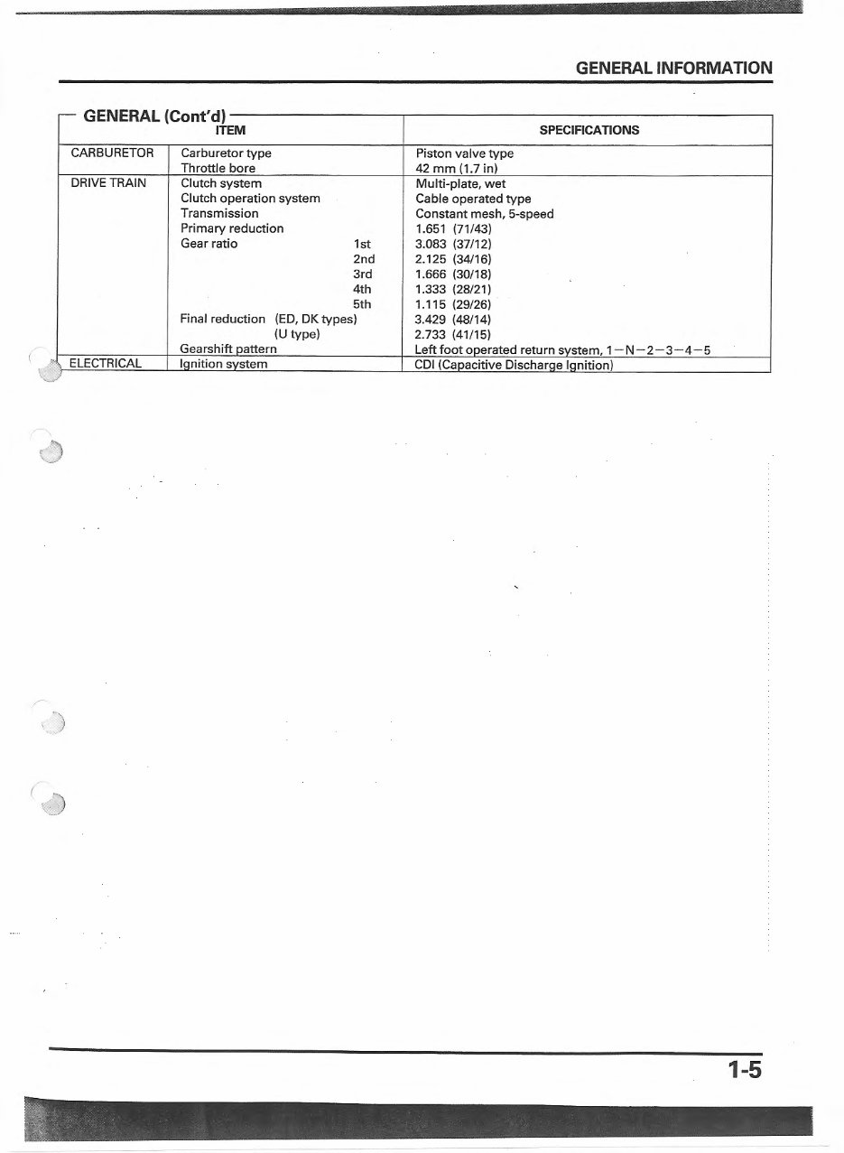
- GENERAL (Cont'd)
ITEM SPECIFICATIONS
CARBURETOR Carburetor type Piston valve type
Throttle bore 42 mm (1.7 in)
DRIVE TRAIN Clutch system Multi-plate, wet
Clutch operation system Cable operated type
Transmission Constant mesh, 5-speed
Primary reduction 1.651 (71 /43)
Gear ratio 1st 3:083 (37/12)
2nd 2.125 (34/16)
3rd 1.666 (30/18)
4th 1.333 (28/21)
5th 1.115 (29/26)
Final reduction (ED, DK types) 3.429 (48/14)
(U type) 2.733 (41 /15)
Gearshift oattern Left foot ooerated return svstem, 1- N- 2- 3-4-5
t, ELECTRICAL lanition svstem CDI (Caoacitive Discharae lanition)
()
"-··
1-5
GENERAL INFORMATION
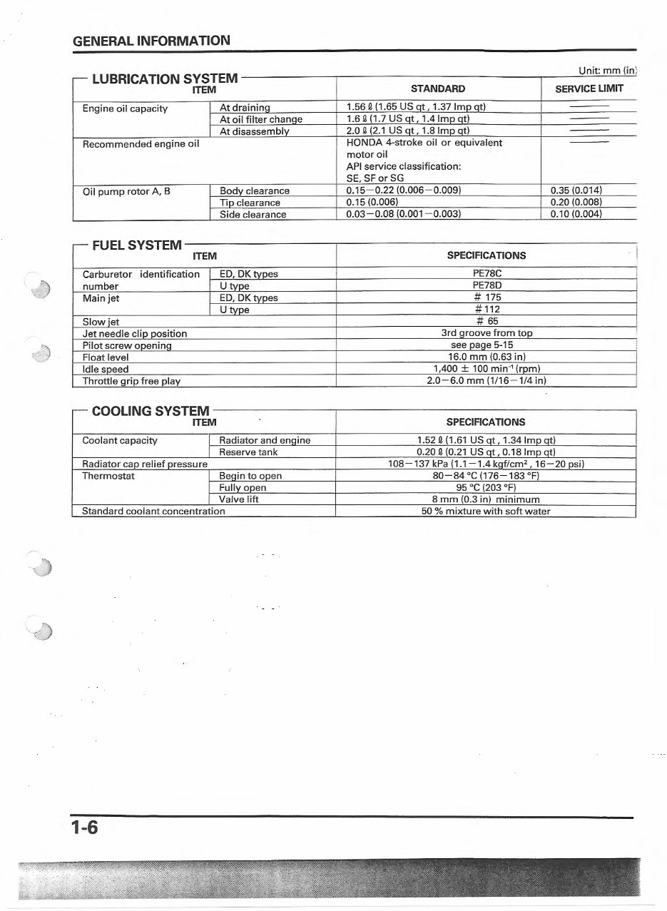
~ LUBRICATION SYSTEM
ITEM STANDARD SERVICE LIMIT
Unit· mm (in)
Engine oil capacity At drainina 1.56 2 (1.65 US nt, 1.37 lmn nt)
At oil filter chanae 1.6 2 (1.7 US at, 1.4 Imo at)
At disassemblv 2.0 2 (2.1 US at, 1.8 Imo at)
Recommended engine oil
HONDA 4·stroke oil or equ ivalent
motor oil
API service classification:
SE, SForSG
Oil pump rotor A, 8 Bodv clearance 0.15- 0.22 (0.006- 0.009) 0.35 (0.014)
Tio clearance 0.15 (0.006) 0.20 (0.008)
Side clearance 0. 03-0.08 (0.001 - 0.003) 0.10 (0.004)
ELS
~FU
YSTEM
i ITEM SPECIFICATIONS
Carburetor identification ED, DKtvoes PE78C
number Utvoe PE78D
Main jet ED, DK tvoes # 175
Utvoe # 112
Slow iet # 65
Jet needle clio oosition 3rd aroove from too
!
Pil ot screw ooeninq see oaae 5· 15
Float level 16.0 mm (0.63 in)
Idle soeed 1,400 ± 100 min·
1
(rom)
Throttle grip free play 2.0-6.0 mm (1/16 -1 /4 in)
- COOLING SYSTEM
ITEM SPECIFICATIONS
Coolant capacity Radiator and enaine 1.52 2 (1 .61 US at, 1.34 Imo at)
Reserve tank 0.20 2 (0.21 US at, 0.18 Imp qt)
Radiator cao relief oressure 108- 137 kPa (1.1-1.4 kaf/cm
2
, 16- 20 osi)
Thermostat Beain to ooen 80-84 °C (176 -1 83 °F)
Fully open 95 °C (203 °F)
Valve lift 8 mm (0.3 in) minimum
Standard coolant concentration 50 % mixture with soft water
,)
1-6
GENERAL INFORMATION
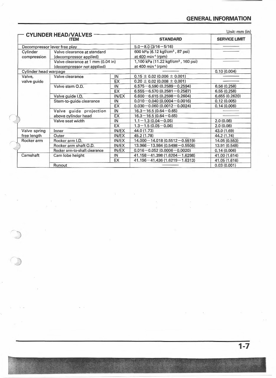
- CYLINDER HEAD/VALVES
Unit mm (in)
ITEM STANDARD SERVICE LIMIT
Decomoressor lever free olav 5.0- 8.0 (3/16-5/16)
Cylinder Valve clearance at standard 600 kPa (6.12 kgf/cm
2
, 87 psi)
compression (decornoressor annlied) at 400 min-
1
(rpm)
Valve clearance at 1 mm (0.04 in) 1, 100 kPa (11.22 kgf/cm
2
, 160 psi)
(decomoressor not aoolied) at 400 min-
1
(rom)
Cvlinder head waroaqe 0.10 (0.004)
Valve, Valve clearance IN 0.15 ± 0.02 (0.006 ± 0.001)
valve guide EX 0.20 ± 0.02 (0.008 ± 0.001)
Valve stem O.D. IN 6.575-6.590 (0.2589-0.2594) 6.56 (0.258)
EX 6.555- 6.570 (0.2581-0.2587) 6.55 (0.258}
Valve quide l.D. IN/EX 6.600 - 6.615 (0.2598 -0.2604) 6.655 (0.2620)
Stem-to-guide clearance IN 0.010- 0.040 (0.0004-0.0016) 0.12 (0.005)
EX 0.030-0.060 (0.0012-0.0024) 0.14 (0.006)
Valve guide projection IN 16.3- 16.5 (0.64 - 0.65)
above cvlinder head EX 16.3- 16.5 (0.64-0.65)
')
Valve seat width IN 1.1 - 1.3 (0.04-0.05) 2.0 (0.08)
EX 1.3- 1.5 (0.05- 0.06) 2.0 (0.08)
Valve spring Inner IN/EX 44.0 (1.73) 43.0 (1.69)
free lenQth Outer IN/EX 45.2 (1 .78) 44.2 (1.74)
Rocker arm Rocker arm l.D. IN/EX 14.000- 14.018 (0.5512-0.5519) 14.05 (0.553)
Rocker arm shaft O.D. IN/EX 13.966-13.984 (0.5498-0.5506) 13.91 {0.548)
Rocker arm-to-shaft clearance IN/EX 0.016-0.052 (0.0006-0.0020) 0.14 (0.006)
Camshaft Cam lobe height IN 41.158-41.398 (1 .6204-1.6298) 41.00 (1.614)
EX 41.196-41.436 (1.6219 - 1.6313) 41 .05 (1.616)
Run out 0.03 (0.001)
j)
1-7
You're Reading a Preview
What's Included?
Fast Download Speeds
Online & Offline Access
Access PDF Contents & Bookmarks
Full Search Facility
Print one or all pages of your manual
$27.99
$36.99
Viewed 85 Times Today


Secure transaction
What's Included?
Fast Download Speeds
Online & Offline Access
Access PDF Contents & Bookmarks
Full Search Facility
Print one or all pages of your manual
$27.99
$36.99
This comprehensive service manual is specifically designed for the Honda XR650, covering the model years 2000, 2001, 2002, and 2003. It provides detailed guidance for both professional mechanics and DIY enthusiasts. Whether you need to perform routine maintenance or tackle more complex repairs, this manual offers the essential information you need. Access the complete manual instantly to gain valuable insights into servicing and maintaining your Honda XR650.


