

1986-1999 XR200R Service & Repair Manual
What's Included?
Fast Download Speeds
Online & Offline Access
Access PDF Contents & Bookmarks
Full Search Facility
Print one or all pages of your manual

B8·99
XR200R
IMPORTANT SAFETY NOTICE
IndiC/Jtu II sIrQn, possibility 0/ S'~'trt pnsona/ injury or Joss of li/~ if ifU1TUctiOf/$ art n ot jolID .. :td.
CAUTION : Indicates Q po$SibilifY oj personal injury or equipment damage if Instructions are nof followed.
NOTE: Gives hel pfu l information.
Detailed descriptions of standard workshop procedures. safety principles and service operations are nol included.
11 IS imponant to note that th IS manual contains some warnings and cautions agamst some speclhc service methods
which could cause PERSONAL INJURY 10 service personnel or could damage a vehicle or render it unsafe. Plea se
understand thai thoss warnings could not cover aU conceivable ways in which service. whether or not recommended
by Honda, might be done or of the possibly hazardous consequences of each conceivable way, nor could Honda
investigate all such ways . Anyone using service procedures or tools, whether or not recommended by Honda, must
satisfyhimseJf thoroughly that neither personal safety nor vehicle safety wiN be jeopardized by the service methods or
tools selected.
1
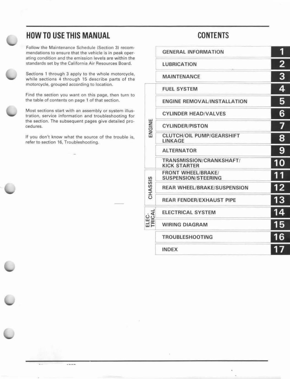
HOW TO USE THIS MANUAL
Follow the Maintenance Schedule (Section 3) recom -
mendations to ensure that the vehicle is in peak oper-
ating condition and the emission levels are within the
standards set by the California Air Resources Board.
Sections 1 through 3 apply to the whole motorcycle,
whi le sections 4 through 15 descr ibe parts of the
motorcycle, grouped according to location.
Find the section you want on this page, then turn to
the table of contents on page 1 of that section.
Most sections start with an assembly or system illus-
tration, service information and troubleshooting f or
the section. The subsequent pages give detailed pro-
cedures.
If you don't know what the source of the trouble is,
refer to section 16, Troubleshooting .
CONTENTS
GENERAL INFORMATION
~BRICATION
MAINTENANCE
FUEL SYSTEM
ENGINE REMOVAL/INSTALLATION
CYLINDER HEAO/V ALVES
w ~===========-~========
Z CYLINDER/PISTON
~ r==CLlrn~UCmLlPi~~~EA~iHlFr===~======
ALTERNATOR
REAR WHEEL/ BRAKE/SUSPENSION
REAR FENDER /EXHAUST PIPE
ELECTRICAL SYSTEM
WIRING DIAGRAM
TROUBLESHOOTING
INDEX

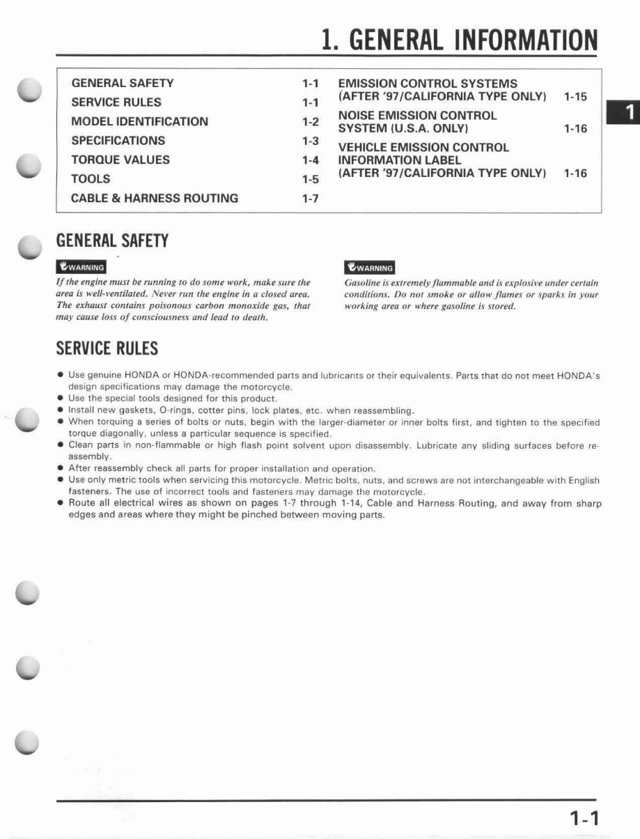
GENERAL SAFETY
SERVICE RULES
MODEL IDENTIFICATION
SPECIFICATIONS
TORQUE VALUES
TOOLS
CABLE & HARNESS ROUTING
GENERAL SAFETY
,.,
,.,
, ·2
, ·3
'·4
,·5
' ·7
afeu is wd/-I't!ntilated. Nel'ef run lhe engine in a closed area.
The exhaust comain! poisonous carbon monoxide gas, thaI
may cause loss 0/ consciousness and lead to (Iel/th.
SERVICE RULES
1. GENERAL INFORMATION
EMISSION CONTROL SYSTEMS
(AFTER '97/CALIFORNIA TYPE ONLYI
NOISE EMISSION CONTROL
SYSTEM IU .S.A. ONLYI
VEHICLE EMISSION CONTROL
INFORMATION LABEL
(AFTER '97/CALIFORNIA TYPE ONLY)
¥!
, . , 5
'· '6
, · '6
Casvline is rxfremely flammable and is exp{osil't! under certain
condilions. Do not smoke or allow flames or sparks in your
working afta or when' gasolint is stored.
• Use genuine HONDA Of HONDA- re commended parts and lubricants or their equivalents. Parts that do not meet HONDA 's
design specifications may damage the motorcycle .
• Use the special tools designed for this product.
• Install new gaskets, D-rings , cotter pins, lock plates, etc. when reassembling.
• When torquing a series of bolts or nuts, begin with the larger-diameter or inner bolts first, and tighten to the specified
torque diagonallv, unless a parti cular sequence is specified .
• Clean parts in non-flammable or high flash point solvent upon disassemblv. Lubricate any sliding surfaces before re-
assembly.
• After reassembly check aU parts for proper installation and ope rat ion.
• Use only metric tools when servicing this motorcycle. Metric bolts, nuts, and screws are not interchangeable with English
fasteners. The use of incorrect tools and fasteners may damage the motor cycle.
• Route all electrical wires as shown on pages 1-7 through '- '4, Cable and Harness Routing, and away from sharp
edges and areas where they might be pinched between moving parts.
1-1
GENERAL INFORMATION
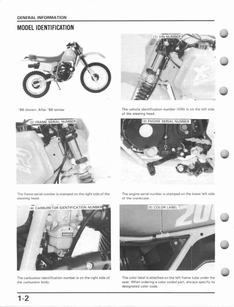
MODEL IDENTIFICATION
'86 shown: After '86 similar
The frame senal number is stamped on the right side 01 the
steering head.
IC ARBURETOAIDI'Nl·IIIF1ICATIS~~~~
;.
The carburetor identification number is on the right side of
the carburetor body.
1-2
The vehicle identification number (V IN f is on the left side
of the sleering head.
The engine serial number is stamped on the lower left side
of the cran kcase .
The color label is attached on the left frame tube under the
seat. When ordering a color coded part , always specify Its
designated color code.
GENERAL INFORMATION
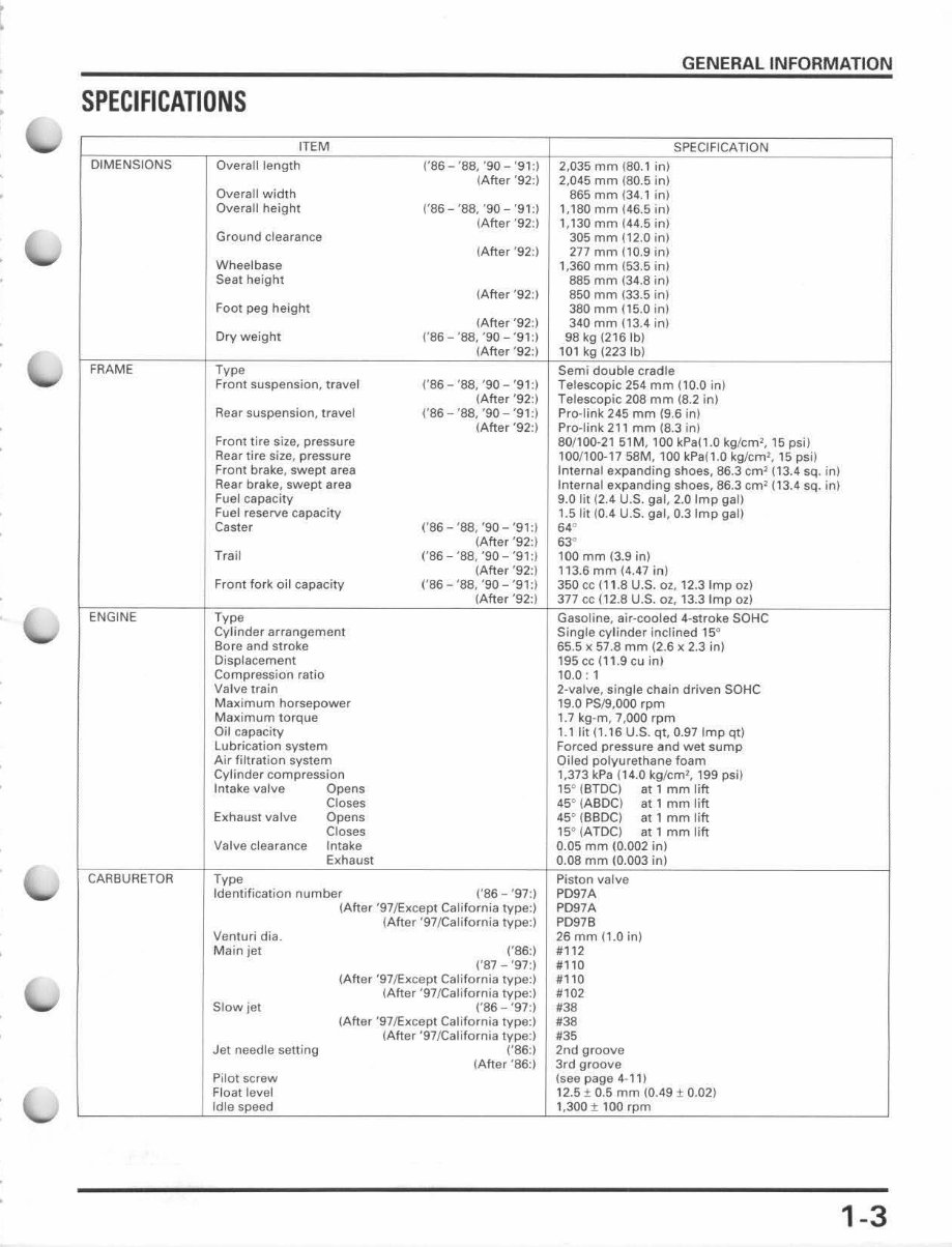
SPECIFICATIONS
ITEM SPECIFICATION
DIMENSIONS Overalileogth (,S6 'S8, '90 - '91 :) 2,035 mm (80.1 in)
(After '92:) 2,045 mm (80.5 in)
Overall width 865 mm (3 4.1 in)
Overall height ('86 - '88, '90 - '91:) 1,180 mm (46.5 in)
(After '92:) 1,130 mm 144.5 in)
Ground clearance 305 mm (12.0 in)
(After '92:) 277 mm (10.9 in)
Wheelbase 1,360 rnm (53.5 in)
Seat height 885 mm (34.8 in)
(After '92:) 850 mm (33.5 in)
Fool peg height 380 mm 115.0 in)
(After '92:) 340 mm (13.4 in)
Dry weight ('86 - 'S8, '90-'91:1 98 kg (216Ib)
(After '92:) 101 kg (223Ib)
FRAME TVpe Semi double cradle
Fron! suspension, travel ('86 - '88, '90 - '9 1: ) Telescopic 254 mm (10.0 in)
(Afte r '92:1 Telescopic 208 mm (8.2 in)
Rear suspension, travel ('86 - '88, '90- '91:) Pro-link 245 mm 19.6 in)
(After '92:) Pro-link 211 mm 18.3 in)
Front tire size, pressure 80/100-21 51M, 100 kPa(1 .0 kg/cm', IS psi)
Aear tire size, pressure 100/100-17 SSM, 100 kPa (l .0 kg/cm l, 15 psi)
Front brake, swept area Internal expanding shoes, 86.3 em' (13.4 sQ. in)
Aear brake, swept area Internal expanding shoes, 86.3 em' (13.4 sQ. in)
Fuel capacity 9.0 lit (2.4 U.S. gal, 2.0 Imp gall
Fuel reserve capacity 1.5 lit (0.4 U.S. gal, 0.3 Imp gal)
Caster ('86 - '88, '90 - '91:) 64"
(After '92:) 63°
Trail ('86 - '88, '90 - '91:) 100 mm (3.9 in)
(Aft er '92:) 113.6 mm (4.47 in)
Front fork oil capacity ('86 - '88, '90 - '91:) 350 cc (1 1.8 U.S. OZ, 12.3 Imp oz)
(After '92:) 377 cc 112.8 U.S. OZ, 13.3 Imp 02)
ENGINE Type Gasoline, air-cooled 4-stroke SOHC
Cylinder arrangement Single cyl inder inclined IS"
Bore and stroke 65.5 x 57.8 mm (2.6 x 2.3 in)
Disp(acement 195 cc (1'.9 cu in)
Compression ratio 10.0: I
Valve train 2-valve, single chain driven SOHC
Maximum horsepower 19.0 PS/9,OOO rpm
Maximum torque 1.7 kg-m, 7,000 rpm
Oil capacity 1.1 lit (1.16 U.S. qt, 0.97 Imp qt)
Lubrication system FOfced pressure and wet sump
Air filtration system Oiled polyurethane foam
Cylinder compression 1,373 kPa (14.0 kgJcm2, 199 psH
Intake valve Opens 15° (BTOC) at I mm lift
Closes 45° (ABDC) at 1 mm lift
Exhaust valve Opens 45" (BBDC) at I mm lift
Closes 15" (ATDC) at 1 mm lift
Valve clearance Intake 0.05 mm (0.002 in)
Exhaust 0.08 mm (0.003 in)
CARBURETOR Type Piston valve
Identification number ('86 - '97:) PD97A
(After '97~xcept California type:) P097A
(After '97/Cali fornia type:) P097B
Venturi dia. 26 mm (1.0 in)
Mainjel ('86:) #112
('87 - '97:) #110
(After '97~xcept California type:) #110
(After ·97/California type:) #102
Slow jet ('86 - '97:)
'38
(After ·97~xcept California type:)
'''' (After '97/California type:) #35
Jet needle selting ('86:) 2nd groove
(After '86:) 3rd groove
Pilot screw (see page 4-1 1)
Float level 12.5 ± 0.5 mm (0.49 ± 0.02)
Idle speed 1,300± 100 rpm
1-3
GENERAL INFORMATION
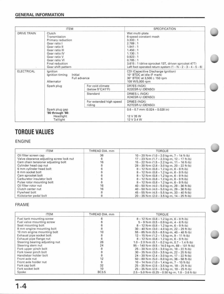
ITEM
DRIVE TRAIN Clutch
Transmission
Primary reduction
Gear ratio I
Gear ratio II
Gear ratio II I
Gear ratio IV
Gear ratio V
Gear ratio VI
Final reduction
Gear shih pattern
elECTRICAL Ignition
Ignition timing Initial
Full advance
Alternator
Spark plug For cold climate
(below 5°C/41"F)
Standard
For extended high speed
riding
Spark plug gap
'86 through '88:
Headlight
Teillight
TORQUE VALUES
ENGINE
ITEM THREAD DIA. mm
Oil filter screen cap 36
Valve clearance adjusting screw lock nu t 6
Cam chain tensioner adjusting bolt 16
Cvlinder head cap nu t
,
6 mm cylinder head bolt 6
6 mm socket bolt 6
Cam sprocket bolt 6
Carburetor insulator bolt 6
Pulse rotor mounting bolt 6
Oi l filter rotor nut 16
Clutch center nut 16
Flywheel bolt
,
Kickstarter pedal bolt 8
FRAME
ITEM THREAD CIA. mm
Fuel tank mount i ng screw 6
Fuel valve mounting screw 6
Seat mounti ng bolt 6
8 mm engine mounting bolt 8
10 mm engi ne mounting boll 10
Exhaust pipe socket bolt 8
Exhaust pipe flange nut 6
Steering bearing adjusting nut 26
Steering stem nut 24
Fork upper pinch bolt 8
Fork lower pinch bolt 8
Hand lebar holder bolt
,
Fro nt axle nut 12
Front ax le holder nut 6
Fork cap boll J2
Fork socket bolt 10
Spoke Be3.5
1-4
SPECIFICATION
Wei mu lti·plate
6-speed constant mesh
3.333: 1
2.769 : ,
1.941: 1
1.450 : 1
t, 130: 1
0.923: 1
0.785 : 1
3.615: 1 (drilill sprocket 13l , drivsn sprocket 47T)
left foot operated return system t 1 - N - 2 - 3 - 4 - 5 - 6)
COl (Capacitive Discharge Igniti on )
lOa BTDC at idle IF mark)
JO° BTDC at 3,500 ± 1 SO rpm
108 W{5,OOO rpm
DR7ES (NGK)
X22 ESR-U (DENSO)
DABES-l (NGK)
X24ES A-U (DEN SO)
OASES (NGK)
X27ESR-U (DENSD)
0.6 - 0.7 mm (0.024 - 0.028 in)
12 V 35 W
12V3.4 W
TORQUE
10 - 20 N·m (1.0 - 2.0 kg -m, 7 - 14 ft·lb)
17 - 23 N·m 11.7 - 2.3 kg·m, 12 - 17 ft -Ib)
15 - 22 N·m (1 .5 - 2.2 kg-m, 11 - 16 ft-Ib)
28 - 30 N·m (2.8 - 3.0 kg-m. 20 - 22 ft-Ib)
8 - 12 N·m (0.8 - 1.2 kg-m. 6 - 9 ft-Ib)
8 - 12 N·m (0.8 - 1.2 kg -m, 6 - 9 ft -Ib)
8- 12 N·m (0.8 -1 .2 kg-m, 6 - 9 ft-Ib)
8 - 12 N·m (0.8 -1 .2 kg-m. 6 - 9 ft-Ib)
8 - 12 N·m (0.8 -1.2 kg-m. 6 - 9 ft-Ib)
40 - 50 N·m 14 .0 - 5.0 kg-m. 29 - 36 ft·lb)
40 - 50 N·m (4 .0 - 5,0 kg-m. 29 - 36 ft -Ib)
45 - 55 N·m (4.5 - 5.5 kg -m. 33 - 40 ft·lb)
20 - 35 N·m (2.0 - 3.5 kg-m. 14 - 25 ft -Ib)
TORQUE
8- 12 N·m (0.8 1.2 kg-m. 6 9 ft-Ib)
5 - 9 N·m (0.5 - 0.9 kg-m, 4 - 6 ft -Ib)
8 - 12 N'm (0.8 - 1.2 kg -m. 6 - 9 ft-Ib)
30 - 40 N·m 13 .0 - 4.0 kg -m. 22 - 29 ft -Ib)
55 - 65 N·m (5.5 - 6.5 kg -m. 40 - 48 ft -Ib)
12 - 15 N·m 11.2 - 1.5 kg -m. 9 - 11 ft -Ib)
8 - 12 N'm (0.8 - 1.2 kg -m. 6 - 9 ft-Ib)
1.0 - 2.0 N·m (0.' - 0.2 kg -m . 0.7 - 1.4 ft-Ib)
95 - 140 N·m (9.5 - 14.0 kg-m, 69 - 101 ft·l b)
25 - 30 N·m 12,5 - 3.0 kg-m. 18 - 22 ft-Ib)
30 - 35 N·m (3.0 - 3.5 kg -m. 22 - 25 ft ·lb)
24 - 30 N·m (2.4 - 3.0 kg-m, 17 - 22 ft -Ib)
50 - 80 N·m (5.0 -8.0 kg-m, 36 - 58 ft-lb)
10 -14 N'm (1 .0 - 1.4 kg-m, 7 - 10 ft -Ib)
25 - 35 N·m (2.5 - 3.5 kg-m, 18 - 25 ft -Ib)
25 - 35 N·m (2.5 - 3.5 kg-m. 18 - 25 ft-Ib)
2.5 - 5.0 N·m (0.25 - 0.50 kg ·m, 1.8 - 3.6 ft-Ib)
j
1
1
1
1
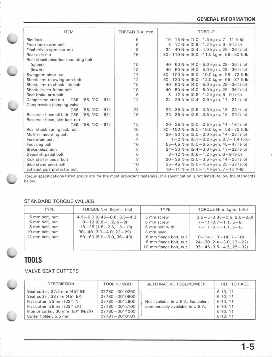
GENERAL INFORMATION
ITEM THREAD OIA . mm TORQUE
Rim lock 6 10 - 15 N'm (1.0 - 1,5 kg -m . 7- 1' ft-Ib)
Front brake arm bolt 6 8- 12 N·m 1 0.8-1.2 kg-m , 6-9 ftolh )
Final driven sprocket nut 8 34 - 40 N·m (3.4 - 4.0 kg -m , 25-29 ft-lb l
Rear axle nut 16 80 - 1,0 N'm (8.0 - " .0 kg-m. 58-80 ft-Ib l
Rear shock absorber mounting bolt
(upper ) 10 40-50 N' m (4 .0 - 5.0 kg-m. 29 - 36 ft -Ibl
(lower ) 10 40 - 50 N·m (4 .0 - 5.0 kg -m , 29 - 36 ft -I bl
Swingarm pivot nut 14 80 - 100 N·m (8 .0 - 10 .0 kg-m, 58 - 72 tHb )
Shock arm -ta- swing arm bolt 12 90 -1 20 N'm (9 . 0- 12.0 kg -m, 65- 87 h-Ib )
Shock arm - ta- shock link bolt 10 40 - 50 N·m (4.0- 5.0 kg -m , 29-36 ft-Ib )
Shock link - la- frame bolt 10 40-50 N·m (4.0 - 5.0 kg-m . 29 - 36 ft-Ib )
Rear brake arm bolt 6 8- 12 N·m m.8 - 1.2 kg - m. 6- 9 ft -Ib l
Damper rod end nut (' 86-'S8 , '90 - '91: ) 12 24 - 29 N·m ~ 2.4 - 2 . 9 kg·m, 17 - 21 ft -Ib)
Compression damping valve
(' 86- ' 88 , ' 90 -' 91: ) 24 25 - 35 N·m (2.5 - 3.5 kg -m , 18 - 25 ft -Ib)
Reservoir hose oil bolt (' 86 - '88, '90 - '91
"
10 25 - 35 N'm (2.5- 3.5 kg -m, 18 - 25 ft -Ib)
Reservoir hose joi nt lock nut
(' 86 - '88 , '90 - '91 :) 12 20-25 N·m (2.0-2 .5 kg-m, 14-18 ft ·lb)
Rear shock spring l ock nut 46 80 - 100 N·m (8 .0 - 10 .0 kg -m. 58 - 72 ft -Ib)
Muffler mounting bolt 8 20 - 30 N·m 12 .0- 3.0 kg-m, 14 - 22 ft -Jb )
Fork drain bolt 4 1 - 2 N'm 10 . 1 - 0.2 kg-m, 0.7- 1.4 ft -Ib)
Foot peg bolt 10 55-65 N·m 1 5.5-6.5 kg-m, 40-47 ft-Ib )
Brake pedal bolt 8 24 - 30 N'm 1 2.4 - 3.0 kg-m , 17 - 22 fHb )
Gearshift pedal bolt 6 8 - 1 2 N'm W .8 - 1.2 kg-m, 6- 9 fHb )
Kick starter pedal bolt 8 20-35 N·m iZ.0-3.5 kg-m , 14-25 ft-Ib )
Side stand pivot bolt 10 35 - 45 N·m 1 3.5 - 4.5 kg -m, 25 - 33 ft ·lb)
Exhaust pipe protector bolt 6 10 - 14 N·m (1 .0 - 1.4 kg -m, 7 - 1 0 ft -Ib)
To rQue speclftcatlons listed above are for the most Important fasteners. If a specification IS not listed , fonow the standards
below.
STANOARD TORQUE VALUES
TYPE TORQUE N·m (kg-m, ft-Ib) TYPE TORQUE N·m (kg-m, ft -Ib)
5 mm bolt , nut 4.5 - 6.0 (0.45 - 0.6, 3.3-4.3) 5 mm screw 3.S- S (0. 35 - 0.S, 2.S- 3.6)
6 mm bolt, nut 8- 12 W .8 - 1.2 , 6 - 9) 6 mm screw 7-11 (0.7- 1.1, 5- 8)
8 mm bolt, nut 18 - 25 1 1.8-2.5 , 13-181 6 mm bolt with 7- 11 (0.7- 1.1.5 - 8)
10 mm bolt , nut 30 - 40 ( 3.0 - 4.0 , 22-291 8 mm head
12 mm bolt, nut 50 - 6015.0 - 6.0,36-43) 6 mm flange bolt , nut 10 - 14 (1.0 - 14, 7- 10 )
8 mm flange bolt, nut 24 - 30 (2.4 - 3.0,17 - 22 )
10 mm ftange batt, nut 35-45 (3.5-4 .5, 25 - 32)
TOOLS
VALVE SEAT CUTTERS
DESCRIPTION TOOL NUMBER ALTERNATIVE TOOL/NUMBER REF. TO PAGE
Seat cutter, 27.5 mm (45
0
IN) 07780 - 0010200
)
6· 10, 11
Seat cutter, 33 mm (45
0
EX ) 07780-0010800 6- 10, 11
Flat cutter , 33 mm (32
0
IN) 07780-0012900 Not available in U.S.A . EQuivalent 6- 10.11
Flat cutter , 28 mm (32
0
EX) 07780 - 0012100 commercially available in U.S.A. 6- 10, 11
Interior cutter, 30 mm (60
0
IN/EX) 07780 - 0014000 6· 10, 11
Cutter holder, 5.5 mm 07781 -0010101 6- 10,"
1-5
.
GENERAL INFORMATION
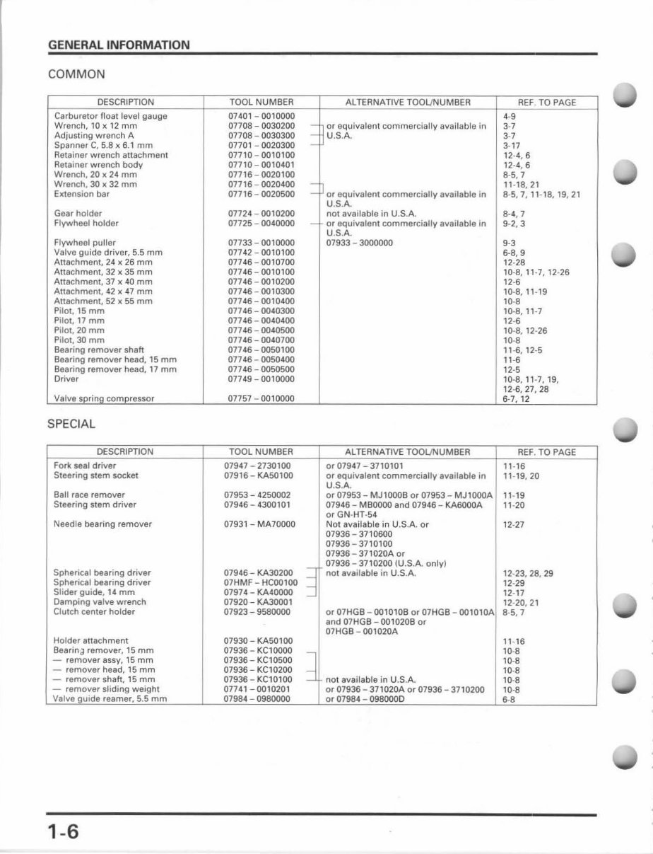
COMMON
DESCRIPTION TOOL NUMBEA
Carburetor float level gauge 07401 - 0010000
Wrench. l Ox 12 mm 07708 - 0030 200 -
Adjusting wrench A 07708 - 0030300
:
Spanner C, 5.8 x 6.1 mm 07701 - 0020300
Re tainer wrench attachment 07710 - 0010100
Retainer wrench body 07710 - 0010401
Wrench, 20 x 24 mm 07716-0020100
Wrench, 30 x 32 mm 07716 - 0020400
:
EKtansion bar 07716-0020500
Gear holder 07724 - 0010200
Flywheel holder 07725 - 0040000 -
Flywheel puller 07733 - 0010000
Valve guide driver, 5.5 mm 07742 - 0010100
Attachment, 24 x 26 mm 07746 -00 10700
Attachment, 32 x 35 mm 07746-00 10100
Attachment, 37 x 40 mm 07746 - 00 10200
Attachment, 42 x 47 mm 07746 -00 10300
Attachment, 52 x 55 mm 07746 - 00 10400
Pilot, 15 mm 07746-0040300
Pilot, 17 mm 07746-0040400
Pilot, 20 mm 07746 - 0040500
Pilol. 30 mm 07746 -00 40700
Bearing remover shah 07746 - 0050100
Bearing remover head, 15 mm 07746 - 0050400
Beering remover head, 17 mm 07746 - 0050500
Dri ver 07749 - 0010000
Valve sorino compressor 07757 - 0010000
SPE CIAL
DESCRIPTION TOOL NUMBER
Fork seal driver 07947 - 2730100
Steering stem socket 07916 - KA50100
Ball race r emover 07953 - 4250002
St eering stem driv er 07946 - 4300101
Needle bearing remover 07931 - MA70000
07946 - KA30200 =l Spherical bearing driver
Spherical bearing driver 07HMF - HCooloo -i
Slider guide, 14 mm 07974 - KA40000 -l
Damping valve wrench 07920 - KA30001
Clutch center holder 07923 - 9580000
Holder attachment 07930 - KA50100
Bearin.} remover, 15 mm 07936 - KC10000
--,
- removerassy, 15 mm 07936 - KC10500
- remover head, 15 mm 07936 - KC10200 ---j
- remover shah , 15 mm 07936 - KC10100 ~
- remover sliding wei ght 07741-0010201
Valve guide reamer, 5.5 mm 07984 - 0980000
1-6
ALTERNATIVE TOOL/NUMBEA
or equivale nt comm ercially available in
U.S. A.
or equivalen t commercially available in
U.S.A.
not avaitable in U.S.A.
or equivalent commercially available in
U.S.A.
07933 - 3000000
ALTERNATIVE TOOlJNUMBER
or 07947 3710101
or equivalent commercially available in
U_S.A.
or 07953 - MJ 1000B Or 07953 - MJ1000A
07946 - MBOOOO and 07946 - KA6000A
or GN -HT-5 4
Not available in U.S.A or
07936 - 3710600
07936-37 10100
07936 - 371020A or
07936 - 3710200 IU.S.A_ only)
not available in U.S.A.
Or 07HGB - oo1010B or 07HGB - 001010A
and 07HGB - oo1020B or
07HGB - oo1020A
no t available in U.S.A.
or 07936 - 371020A or 07936 - 3710200
or 07984 - 0980000
REF . TO PAGE
4-9
3-7
37
3-17
12 -4, 6
1 2-4,6
8-5,7
' ' -l a, 21
8-5,7,11-18,19,21
8·4,7
9·2,3
9-3
6-8,9
12-28
10-8, 11 -7,12 -26
12-6
10-8,11-19
10-8
10--8, 11-7
12-6
10-8, 12-26
10-8
11-6,12-5
11-6
12-5
10-8,11-7,19,
12-6,27,28
6-7,12
REF . TO PAGE
11-16
11 -19,20
11 -19
11-20
12-27
12-23, 28, 29
12-29
12-17
12-20,21
8-5,7
11-16
10-8
10-8
10-8
10-8
10-8
6-8
•
1
1
1
•
1
J
I
,
You're Reading a Preview
What's Included?
Fast Download Speeds
Online & Offline Access
Access PDF Contents & Bookmarks
Full Search Facility
Print one or all pages of your manual
$31.99
$41.99
Viewed 55 Times Today


Secure transaction
What's Included?
Fast Download Speeds
Online & Offline Access
Access PDF Contents & Bookmarks
Full Search Facility
Print one or all pages of your manual
$31.99
$41.99
This repair manual is for the 1986-1999 Honda XR200R four-stroke dirt bike, excluding the 1989 and 1992 models. It encompasses a complete tear down and rebuild, including part diagrams, torque specifications, maintenance, troubleshooting, and more, spanning across 202 pages.
Featuring clickable chapters and a search function, this manual allows for easy navigation to locate specific information. Additionally, there are no restrictions on printing or saving/burning to disc.
- Useful for professional mechanics and DIY enthusiasts
- Includes complete tear down and rebuild
- Contains part diagrams and torque specifications
- Encompasses maintenance and troubleshooting
- Comprises 202 pages
- Clickable chapters and searchable
- No restrictions on printing or saving/burning to disc


