HONDA XLR200R XR200R Service Repair Manual 1987-1999
What's Included?
Lifetime Access
Fast Download Speeds
Online & Offline Access
Access PDF Contents & Bookmarks
Full Search Facility
Print one or all pages of your manual
1 HONDA MOTORS JAPAN SERVICE MANUAL XLR200R / XR200R
This service manual explains the checking and maintenance for the main parts of Honda XLR200. This manual utilizes drawings and symbol marks for easy comprehension and reference. When necessary, detailed explanations and illustrations are used to make this manual easy to use. Chapter 1 summarizes all maintenance figures, values and other information which will become necessary throughout the manual. Chapter 2 indicates the removal and installation specifications for frequently replaced parts. Chapter 3 discusses the methods for checking and maintenance in order to assure vehicle safety and to maintain the functions of each part. Checking and maintenance specific to this vehicle model are also indicated. From Chapter 4 onwards, each part discusses specific parts - Engine, Frame, Electrical Parts. and so on focusing on their specific functions and maintenance specifications. Written specifications and contents may change without prior notice due to improvements on the vehicle. This manual is designed for those with basic knowledge and skills with regard to Honda Motorcycle. For those without these basic knowledge and skills, do not. attempt to make repair what is specified in this Manual. Make sure to consult with your Honda Distributor or Dealer. FOREWORD TABLE OF CONTENTS MAINTENANCE INFORMATION ATTACHMENTS, MUFFLERS CHECKING AND ADJUSTMENTS LUBRICATION SYSTEM FUEL SYSTEM ENGINE REMOVAL AND INSTALLATION CYLINDER HEAD AND VALVE CYLINDER AND PISTON CLUTCH AND GEARSHIFT LINKAGE CRANKSHAFT AND TRANSMISSION FRONT WHEEL, SUSPENSION AND STEERING REAR WHEEL AND SUSPENSION BRAKING SYSTEM RECHARGING SYSTEM AND AC GENERATOR IGNITION SYSTEM STARTER CLUTCH LIGHTS, METERS AND SWITCHES WIRING DIAGRAM E N G I N E F R A M E E L E C T R I C A L S Y S T E M
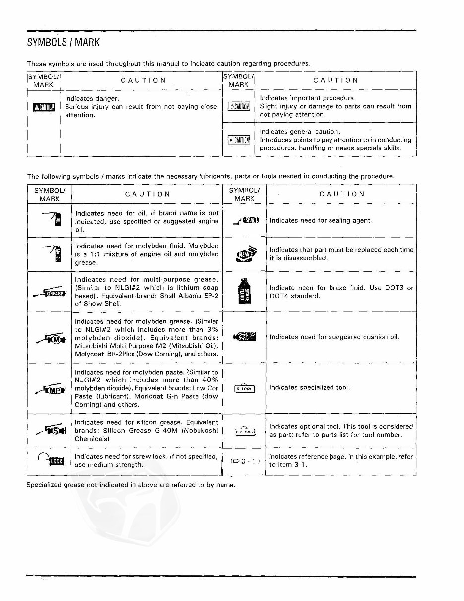
SYMBOLS I MARK These symbols are used throughout this manual to indicate .caution regarding procedures. SYMBOl! CAUTION SYMBOl! CAUTION MARK MARK Indicates danger. Indicates important procedure. mmII Serious injury can result from not paying close I hLAUTIOi 1 Slight injury or damage to parts can result from attention. not paying attention. Indicates general caution. I· CAUliOil Introduces points to pay. attention to in conducting procedures, handling or needs specials skills. The following symbols I marks indicate the necessary lubricants, parts or tools needed in conducting the procedure. SYMBOl! CAUTION SYMBOl! CAUTION MARK MARK -, Indicates need for oil. If brand name is not indicated, use specified or suggested engine _"mIl! Indicates need for sealing agent. oil. -, Indicates need for molybden fluid. Molybden ~ Indicates that part must be replaced each time is a 1: 1 mixture of engine oil and molybden ~ it is disassembled. grease. Indicates need for multi-purpose grease. I ~ (Similar to NLGI#2 which is lithium soap Indicate need for brake fluid. Use OOT3 or .. basedl. Equivalent· brand: Shell Albania EP-2 DOT4 standard . of Show Shell. Indicates need for molybden grease. (Similar to NLGI#2 which includes more than 3% ,~ molybden dioxide). Equivalent brands: eGiiI Indicates need for sU(Tgested cushion oil. Mitsubishi Multi Purpose M2 (Mitsubishi Oil), Molycoat BR-2Plus (Dow Corning), and others. Indicates need for molybden paste. lSimilar to NLGI#2 which includes more than 40% ~ molybd~n dioxide}. Equivalent brands: Low Cor ~ Indicates specialized tool. Paste (lubricant), Moricoat G-n Paste (dow Corning) and others. ~ Indicates need for silicon grease. Equivalent Indicates optional tool. This tool is considered brands: Silicon Grease G-40M INobukoshi [~ Chemicals I as part; refer to parts list for tool number. C),"'" Indicates need for screw lock. If not specified, Indicates reference page. In this example, refer use medium strength. (c:::> 3 - 1 ) to item '3-1. Specialized grease not indicated in above are referred to by name. SYMBOLS I MARK These symbols are used throughout this manual to indicate .caution regarding procedures. SYMBOl! CAUTION SYMBOl! CAUTION MARK MARK Indicates danger. Indicates important procedure. mmII Serious injury can result from not paying close I hLAUTIOi 1 Slight injury or damage to parts can result from attention. not paying attention. Indicates general caution. I· CAUliOil Introduces points to pay. attention to in conducting procedures, handling or needs specials skills. The following symbols I marks indicate the necessary lubricants, parts or tools needed in conducting the procedure. SYMBOl! CAUTION SYMBOl! CAUTION MARK MARK -, Indicates need for oil. If brand name is not indicated, use specified or suggested engine _"mIl! Indicates need for sealing agent. oil. -, Indicates need for molybden fluid. Molybden ~ Indicates that part must be replaced each time is a 1: 1 mixture of engine oil and molybden ~ it is disassembled. grease. Indicates need for multi-purpose grease. I ~ (Similar to NLGI#2 which is lithium soap Indicate need for brake fluid. Use OOT3 or .. basedl. Equivalent· brand: Shell Albania EP-2 DOT4 standard . of Show Shell. Indicates need for molybden grease. (Similar to NLGI#2 which includes more than 3% ,~ molybden dioxide). Equivalent brands: eGiiI Indicates need for sU(Tgested cushion oil. Mitsubishi Multi Purpose M2 (Mitsubishi Oil), Molycoat BR-2Plus (Dow Corning), and others. Indicates need for molybden paste. lSimilar to NLGI#2 which includes more than 40% ~ molybd~n dioxide}. Equivalent brands: Low Cor ~ Indicates specialized tool. Paste (lubricant), Moricoat G-n Paste (dow Corning) and others. ~ Indicates need for silicon grease. Equivalent Indicates optional tool. This tool is considered brands: Silicon Grease G-40M INobukoshi [~ Chemicals I as part; refer to parts list for tool number. C),"'" Indicates need for screw lock. If not specified, Indicates reference page. In this example, refer use medium strength. (c:::> 3 - 1 ) to item '3-1. Specialized grease not indicated in above are referred to by name.
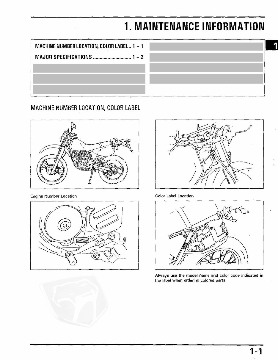
1. MAINTENANCE INFORMATION MACHINE NUMBER LOCATION, COLOR LABEL .. 1 - 1 SPECIALIZED TOOLS ................................... 1 - 14 III MAJOR SPECIFICATIONS ............................. 1 - 2 LUBRICANTS AND SEALANTS ............. • ...... 1 - 16 MAINTENANCE DATA ................................... 1 - 2 WIRING DIAGRAM ....................................... 1 - 17 MAINTENANCE SPECIFICATIONS ................ 1 - 5 TROUBLESHOOTING .................................... 1 - 21 TORQUE ........................................................ 1 - 12 MACHINE NUMBER LOCATION, COLOR LABEL Engine Number Location Color Label Location Always use the model name and color code indicated in the label when ordering colored parts. 1-1
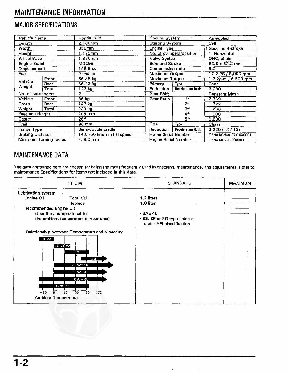
MAINTENANCE INFORMATION MAJOR SPECIFICATIONS Vehicle Name Honda KCN Cooling System Air-cooled Length 2,130mm Starting System Cell Width 850mm Engine Type I Gasoline 4-stroke Height 1,170mm No. of cylinders/position 1. Horizontal Whe!\J Base 1,375mm Valve System OHC, chain Engine Serial MD29E Bore and Stroke 63.5 X 62.2 mm Displacement 196.9 cc Compression ratio 9.0 Fuel Gasoline Maximum Output 17.2 PS 1 8,000 rpm Vehicle Front 56.58 kg Maximum Torque 1.7 kg-m 16,500 rpm Rear 66.42 kg Primary I Type Gear Weight Total 123 kg Reduction I_ Deceleration Ratio 3.090 No. of passengers 2 Gear Shift Constant Mesh Vehicle Front 86 kg Gear Ratio 1" 2.769 Gross Rear 147 kg 2"' 1.722 Weight Total 233 kg 3" 1.263 Foot peg Height 295 mm 4'" 1.000 Caster 26 0 5'" 0.838 Trail 96 mm Final Type Chain Frame Type Semi·double cradle Reduction Deceleration Ratio 3.230 (42 1 13) Braking Distance 14.5 (50 km/h initial speed) Frame Serial Number F'I No KCNOO·97Y·000001 Minimum Turning radius 2,000 mm Engine. Serial Number E I No MD29E-OOOOO1 MAINTENANCE DATA The data contained here are chosen for being the most frequently used in checking, maintenance, and adjustments. Refer to maintenance Specifications for items not included in this data. IT E M STANDARD MAXIMUM Lubricating system Engine Oil Total Vol. 1.2 liters Replace 1.0 liter Recommended Engine Oil (Use the appropriate oil for • SAE 40 the ambient temperature in your area) , SE, SF or SG-type enine oil under API classification Relationship between Temperature and Viscosity • ! • • • r .. • I 10 0 10 20 30 40t; Ambient Temperature 1-2
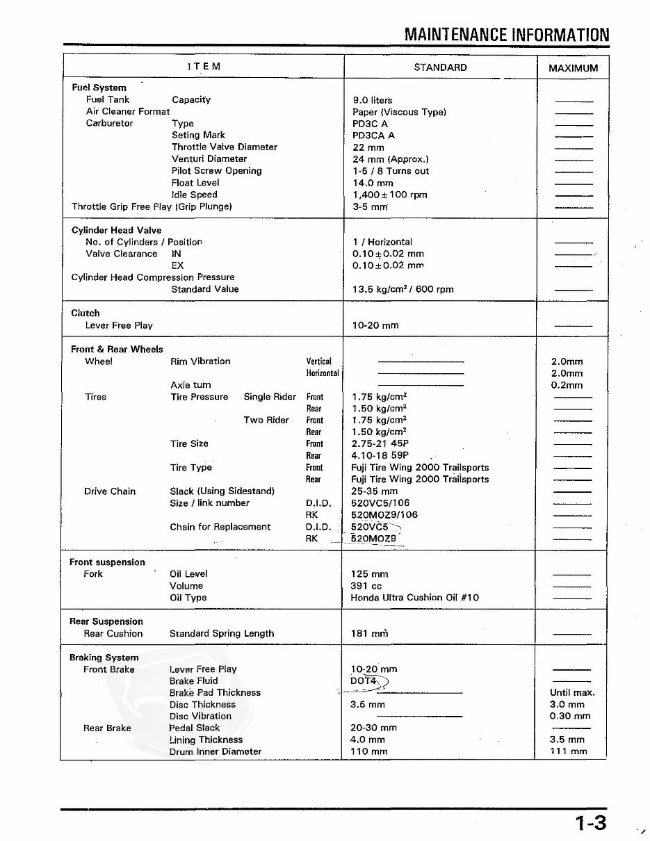
MAIN1ENANCE INFORMATION I T EM STANDARD MAXIMUM - Fuel System Fuel Tank Capacity 9.0 liters Air Cleaner Format Paper (Viscous Type) Carburetor Type PD3C A Seting Mark PD3CA A --- Throttle Valve Diameter 22 mm Venturi Diameter 24 mm (Approx.) Pilot Screw Opening 1-5 / 8 Turns out Float Level 14.0 mm Idle Speed 1 ,400± 100 rpm Throttle Grip Free Play (Grip Plunge) 3-5 mm Cylinder Head Valve No. of Cylinders I Position 1 I Horizontal Valve Clearance IN 0.10;;0.02 mm EX 0.10±0.02 mil' Cylinder Head Compression Pressure Standard Value 13.5 kg/cm'/ 600 rpm Clutch Lever Free Play 10-20 mm Front & Rear Wheels Wheel Rim Vibration Vertical 2.0mm Horizontal 2.0mm Axle turn 0.2mm Tires Tire Pressure Single Rider Front 1.75 kg/cm' Rear 1.50 kg/cm' Two Rider Front 1.75 kg/cm' Rear 1.50 kg/cm' Tire Size Front 2.75-21 45P Rear 4.10-1859P Tire Type Front Fuji Tire Wing 2000 Trailsports Rear Fuji Tire Wing 2000 Traiisports Drive Chain Slack (Using Sidestand) 25-35 mm Size / link number D.I.D. 520VC5!106 RK 520MOZ9/106 Chain for Replacement D.I.D. 520\1(;5-, RK j;20_~OZ9 - ---- -- Front suspension Fork Oil Level 125 mm Volume 391 cc Oil Type Honda Ultra Cushion Oil #10 Rear Suspension Rear Cushion Standard Spring Length 181 mm Braking System Front Brake Lever Free Play 10-20 mm Brake Fluid OOT4)) BraKe Pad Thickness ~,-",,, .. -.=-'- Until max. Disc Thickness 3.5 mm 3.0mm Disc Vibration 0.30mm Rear Brake Pedal Slack 20-30 mm Lining Thickness 4.0mm 3.5 mm Drum Inner Diameter 110 mm 111 mm 1-3
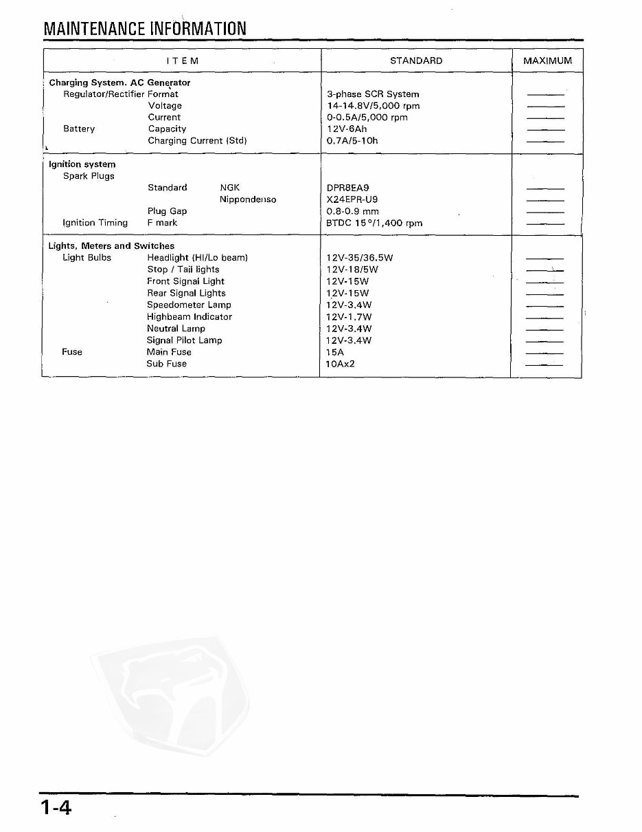
, MAINTENANCE INFORMATION IT E M STANDARD MAXIMUM Charging System. AC GenE\rator Regulator/Rectifier Format 3-phase SCR System Voltage 14-14,8V/S,000 rpm Current O-O.SA/S,OOO rpm Battery Capacity 12 V -6Ah Charging CUrrent (Std) 0.7 A/S-l Oh , Ignition system Spark Plugs Standard NGK DPRSEA9 Nippondenso X24EPR-U9 Plug Gap 0.S-0.9 mm I,gnition Timing F mark BTDC 15 °/1,400 rpm Lights, Meters and Switches Light Bulbs Headlight (Hil La beam) 12V-3S/ 36.SW Stop I Tail lights 12V-1S/5W Front Signal Light 12V-15W Rear Signal Lights '. 2V-'SW Speedometer Lamp 12V-3.4W Highbeam Indicator 12V-1.7W 1 Neutral Lamp 12V-3.4W Signal Pilot Lamp 12V-3.4W Fuse Main Fuse 15A Sub Fuse 10Ax2 1-4
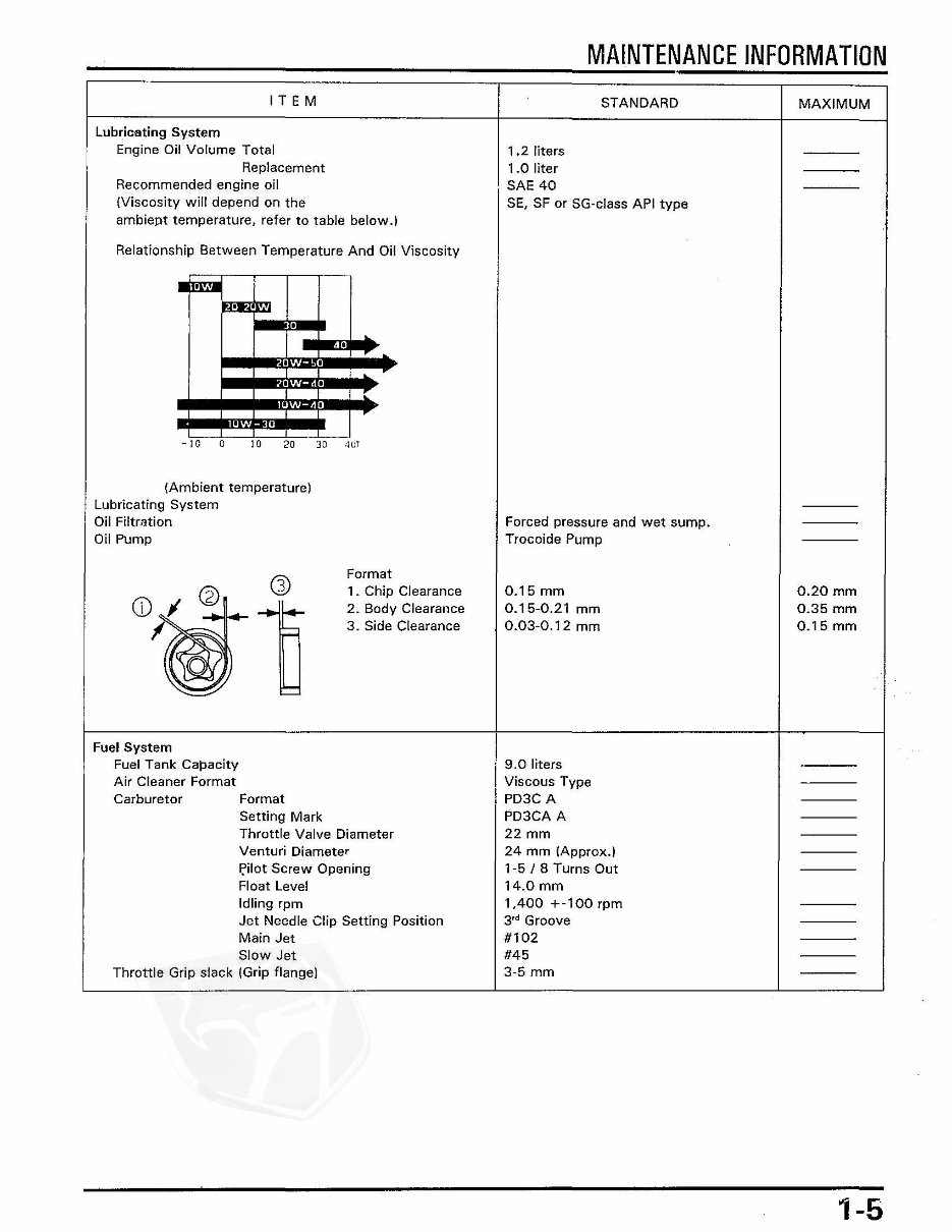
IT E M Lubricating System Engine Oil Volume Total Replacement Recommended engine oil (Viscosity will depend on the ambiept temperature, refer to table below.) Relationship Between Temperature And Oil Viscosity • • . , , , -10 0 10 20 30 40T (Ambient temperature) Lubricating System Oil Filtration Oil Pump Fuel System Fuel Tank Capacity Air Cleaner Format Format 1 . Chip Clearance 2. Body Clearance 3. Side Clearance Carburetor Format Setting Mark Throttle Valve Diameter Venturi Diameter I:'ilot Screw Opening Float Level Idling rpm Jet Needle Clip Setting Position Main Jet Slow Jet Throttle Grip slack (Grip flange) MAINTENANCE INFORMATION 1.2 liters 1.0 liter SAE 40 STANDARD SE, SF or SG-class API type Forced pressure and wet sump. Trocoide Pump 0.15 mm 0.15-0.21 mm 0.03-0.12 mm 9.0 liters Viscous Type PD3C A PD3CA A 22 mm 24 mm IApprox.) 1-5 I 8 Turns Out 14.0 mm 1,400 +-100 rpm 3 fd Groove #102 #45 3-5 mm MAXIMUM 0.20 mm 0.35 mm 0.15 mm 1-5
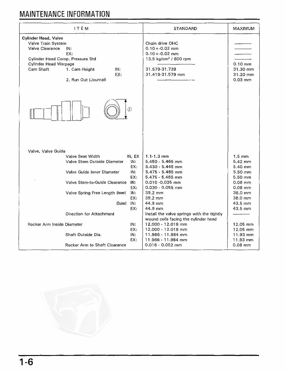
MAINTENANCE INFORMATION IT E M STANDARD MAXIMUM Cylinder Head, Valve Valve Train System Chain drive OHC Valve Clearance IN: 0.10+-0.02 mm EX: 0.10 +-0.02 mm Cylinder Head Compo Pressure Std 13.5 kg/em' / 600 rpm Cylinder Head Warpage 0.10 mm Cam Shaft 1 . Cam Height IN: 31.579-31.739 31.30 mm EX: 31.419-31.579 mm 31.20 mm 2. Run Out (Journal) 0.03 mm rrLIO.J D aJel' Valve, Valve Guide Valve Seat Width IN, EX 1.1-1.3 mm 1.5 mm Valve Stem Outside Diameter IN: 5.450 - 5.465 mm 5.42 mm EX: 5.430 - 5.445 mm 5.40 mm Valve Guide Inner Diameter IN: 5.475 - 5.485 mm 5.50 mm EX: 5.475 - 5.485 mm 5.50 mm Valve Stem-ta-Guide Clearance IN: 0.010 -0.035 mm 0.06 mm EX: 0.030 - 0.055 mm 0.08 mm Valve Spring Free Length (Inner) IN: 39.2 mm 38.0 mm EX: 39.2 mm 38.0 mm (Quler) IN: 44.9 mm 43.5 mm EX: 44.9 mm 43.5 mm Direction for Attachment Instail the valve springs with the tightly wound coils facing the cylinder head Rocker Arm Inside Diameter IN: 12.000 _ 12.018 mm 12.05 mm EX: 12.000 - 12.018 mm 12.05 mm Shaft Outside Dia. IN: 11.966 - 11.984 mm 11.93 mm EX: 11.966 - 11.984 mm 11.93 mm Rocker Arm to Shaft Clearance 0.016 - 0.052 mm 0.08 mm 1-6
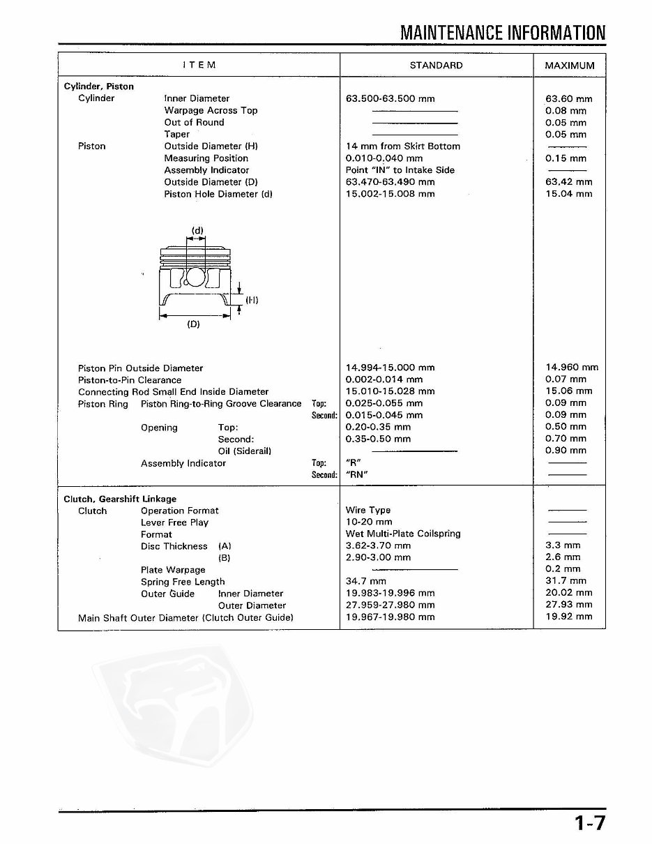
MAINTENANCE INFORMATION Cylinder, Piston Cylinder Piston IT E M Inner Diameter Warpage Across Top Out of Round Taper Outside Diameter (HI Measuring Position Assembly Indicator Outside Diameter (01 PistonHole Diameter (dl ~ -I (, _J • I~ ~ (HI (01 STANDARD 63.500-63.500 mm 14 mm from Skirt Bottom 0.010-0.040 mm Point "IN" to Intake Side 63.470-63.490 mm 15.002-15.008 mm Piston Pin Outside Diameter 14.994-15.000 mm Piston-ta-Pin Clearance 0.002-0.014 mm Connecting Rod Small End Inside Diameter 15.010-15.028 mm Piston Ring Pistbn Ring-ta-Ring Groove Clearance Top: 0.025-0.055 mm Opening Top: Second: Oil (Siderail) Assembly Indicator Clutch. Gearshift linkage Clutch Operation Format Lever Free Play Format Disc Thickness (Al (BI Plate Warpage Spring Free Length Outer C;uide Inner Diameter Outer Diameter Main Shaft Outer Diameter (Clutch Outer Guidel Second: 0.015-0.045 mm Top: 0.20-0.35 mm 0.35-0.50 mm "R" Second: "RN" Wire Type 10-20 mm Wet Multi-Plate Coilspring 3.62-3.70 mm 2.90-3.00 mm 34.7 mm 19.983-19.996 mm 27.959-27.980 mm 19.967-19.980 mm MAXIMUM 63.60 mm 0.08 mm 0.05 mm 0.05 mm 0.15 mm 63.42 mm 15.04 mOl 14.960 mm 0.07 mm 15.06 mm 0.09 mm 0.09 mm 0.50 mm 0.70 mm 0.90 mm 3.3 mm 2.6 mm 0.2 mm 31.7 mm 20.02 mm 27.93 mm 19.92 mm 1-7
Our service repair workshop manual is a comprehensive guide supplied in an easy-to-read format, covering all repairs from A-Z and all models. It is a valuable resource for both professional mechanics and DIY enthusiasts.
The manual covers major repair topics in great detail and includes high-quality pictures and diagrams for easy understanding. It encompasses maintenance and servicing, engine and clutch, transmissions, cooling systems, fuel and exhaust, ignition and electrical, brakes and brake assembly, wheels and tires, steering and suspension, frame and bodywork, wiring diagrams, fault finding troubleshooting, and much more.
Compatible with all operating systems, including PC and MAC, such as Windows 95, 98, 2000, Me, Xp, Vista, and Windows 7, this manual is a professional-quality source of information that can be accessed instantly without any waiting time.
Recently Viewed
5,521,897Happy Clients
2,594,462eManuals
1,120,453Trusted Sellers
15Years in Business
Price:
Actual Price:
HONDA XLR200R XR200R Service Repair Manual 1987-1999