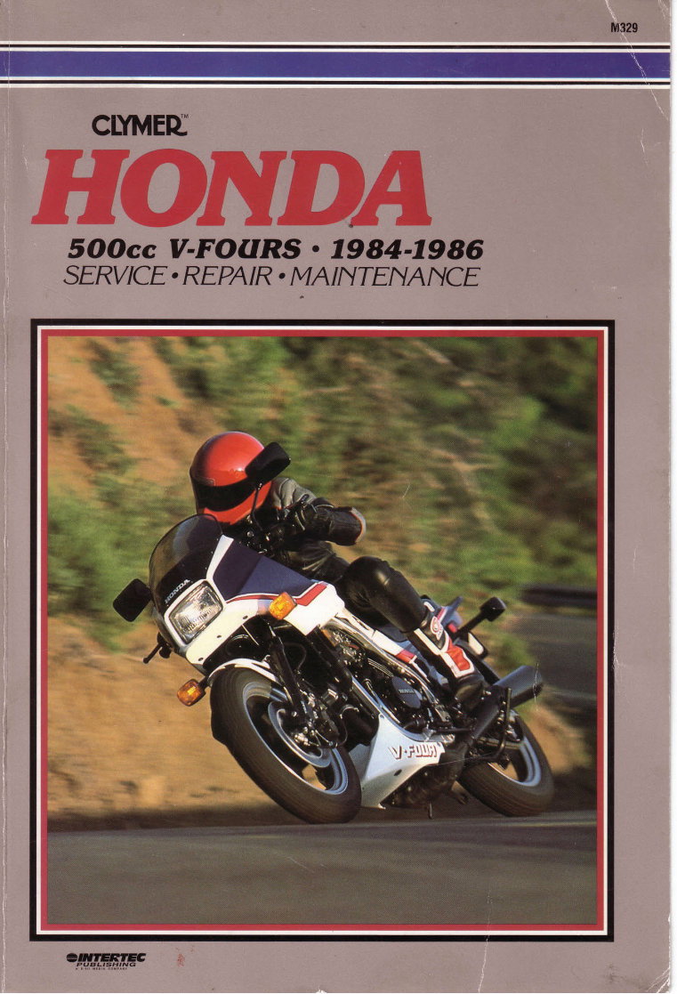
M329 clYlvtEu SOOcc V-FOURS o 7984-7986 SERVICE. REPAIR . I\4AINTEI\AIYCE w =,NTER7EC PUE'L'SH'T!<;
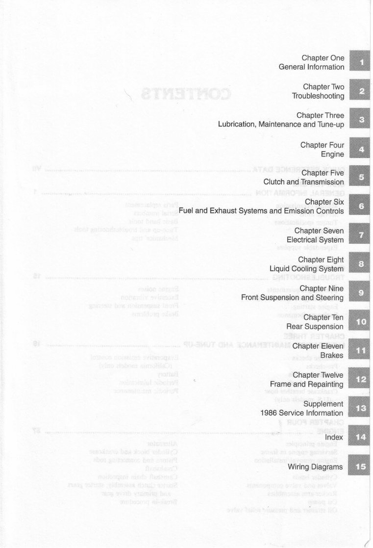
Chapter One General Information Chapter Two Troubleshooting Chapter Three Lubrication, Maintenance andTune-up Chapter Four Engine Chapter Five Glutch and Transmission Chapter Six Fuel andExhaust Systems andEmission Controls Chapter Seven Electrical System Chapter Eight Liquid Cooling System Chapter Nine Front Suspension andSteering Chapter Ten Rear Suspension Chapter Eleven Brakes Chapter Twelve Frame and Repainting Supplement 1986 Service Information Index Wirlng Diagrams ffi l ffi W ffi ffi ffi
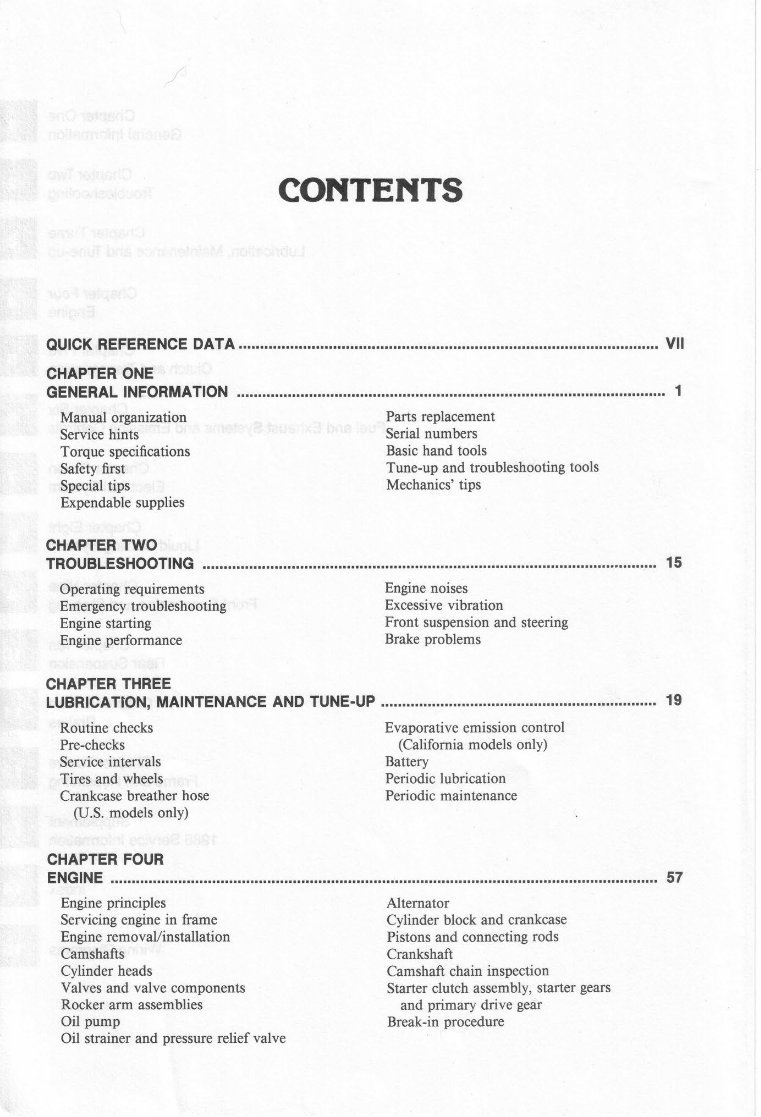
CONTENTS OUICK REFERENCE DATA !..t.r .... r ...... !r .... r.rr .... r .......... r...r .... r .............. r ................ r .............. Vll CHAPTER ONE GENERAL INFORMATION .r.rr.rr ........... t.r.rr ..... r.r ..... r..r ....... r.rr...r.r.r.r..rrr...r .... rr...r ............. r.tr.t 1 Manual organization Parts replacement Service hints Serial numbers Torque speciflcations Basic hand tools Safety first Tune-up and troubleshooting tools Special tips Mechanics'tips Expendablesupplies CHAPTER TWO TROUBLESHOOTING ...... ,..!.r! ..... r.r.r...,.r...r...r .... ,.tr ... ..... !...r., ................. 15 Operating requirements Engine noises Emergency troubleshooting Excessive vibration Engine starting Front suspension and steering Engine performance Brake problems CHAPTER THREE LUBRICATION, MAINTENANCE AND TUNE-UP .,.,..,.r..., .... ,...,...,.,,.,,.., ........... ,..r..r.r.,., .... 19 Routine checks Evaporative emission control Pre-checks (California models only) Service intervals Battery Tires and wheels Periodic lubrication Crankcase breather hose Periodic maintenance (U.S. models only) CHAPTER FOUR ENGINE ..,r.ir ...... rr .,r.r.r.r ...... r.r.,.,..!r .... 57 Engine principles Alternator Servicing engine in frame Cylinder block and crankcase Engine removal/installation Pistons and connecting rods Camshafts Crankshaft Cylinder heads Camshaft chain inspection Valves and valve components Starter clutch assembly,starter gears Rocker arm assemblies and primary drive gear Oil pump Break-in procedure Oil strainer and pressure relief valve
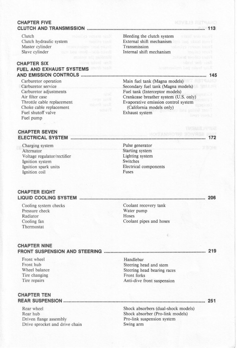
CHAPTER FIVE CLUTCH ANDTRANSMISSION 113 Clutch Bleeding the clutch system Clutch hydraulic system External shift mechanism Master cylinder Transmission Slavecylinder Internal shift mechanism CHAPTER SIX FUEL ANDEXHAUST SYSTEMS AND EMISSION CONTROLS ...!..r,., .... r .... , .... i.i. .., ..... ,,.,.., .... ,...,..,.,., .... ,.. 145 Carburetor operation Main fuel tank (Magna models) Carburetor service Secondary fuel tank (Magna models) Carburetoradjustments Fuel tank (Interceptormodels) Air filter case Crankcase breathersystem(U.S. only) Throttle cable replacement Evaporativeemissioncontrol system Choke cable replacement (California models only) Fuel shutoff valve Exhaustsvstem Fuel pump CHAPTER SEVEN ELECTRICAL SYSTEM ............... ,r,r,r.rr.r,,.r ...... r...,.. 172 Charging system Pulse generator Alternator Starting system Voltage regulator/rectifier Lighting system Ignition system Switches Ignition spark units Electricalcomponents Ignition coil Fuses CHAPTER EIGHT LtQUtD COOLTNG SYSTEM ................... r.. 206 Cooling system checks Coolant recoverytank Pressure check Water pump Radiator Hoses Cooling fan Coolant pipes and hoses Thermostat CHAPTER NINE FRONT SUSPENSION AND STEERING .......... ........ r .......................... i..,..r 219 Front wheel Front hub Wheel balance Tire changing Tire repairs Handlebar Steeringhead and stem Steeringhead bearing races Front forks Anti-dive front suspension CHAPTER TEN REAR SUSPENSION r.r..r.., ................... rt., ........ ,..r, .... r 251 Rear wheel Shockabsorbers (dual-shock models) Rear hub Shockabsorber (Pro-link models) Driven flange assembly Pro-link suspension system Drive sprocket and drive chain Swing arm
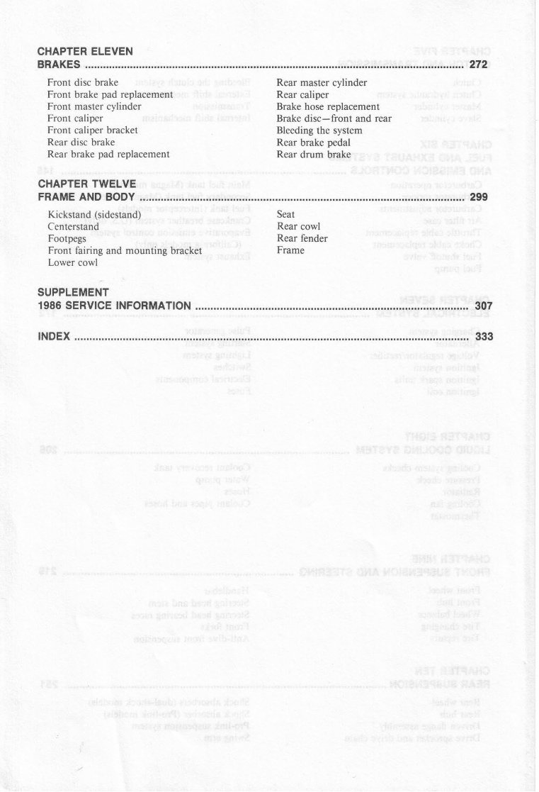
CHAPTER ELEVEN BRAKES .f ..r ..... r..rrr .r.r.r.t.i ..... rr.r.r.r .... rrrrrrrrrrriirr...rtrr.r.rr.r ............. 272 Front disc brake Rear master cvlinder Front brake pad replacement Rear caliper Front master cylinder Brake hose replacement Front caliper Brake disc-front and rear Front caliper bracket Bleeding the system Rear disc brake Rear brake pedal Rear brake pad replacement Rear drum brake CHAPTER TWELVE FRAME AND BODY ..r.rr ...... r.-.,...r.i.r.rrr...t..t.*r .. ..... r..r...r ........ 299 Kickstand (sidestand) Centerstand Footpegs Front fairing and mounting bracket Lower cowl SUPPLEMENT 1986 SERVICE INFORMATION .,r..r, ..... ,,...r,.r ...... , ...... ,..r ..... r,.r..r ......... r .... ,., .... ,.r.r,.i,.i,.r.,..r 307 INDEX r.r.ir...: .... .... r ..... , .... r..333 Seat Rear cowl Rear fender Frame
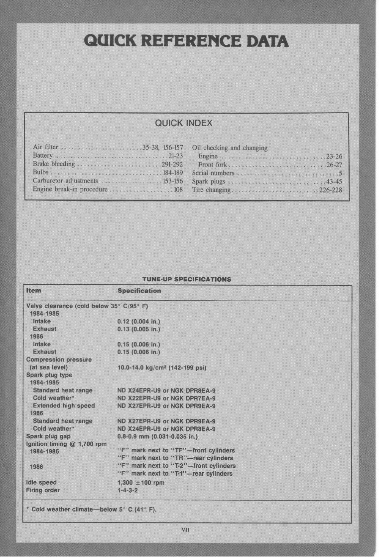
OUICK REFEREITCE DATA . TUNE.UP SPECI FICATIONS QUICK INDEX Baiiery $ge ttdding, !;:I;;ii;$:.;l.i',r, i,'i,'!i';*piw.z. !;ilret"r adjustmpffi i + i # ;i' ; :'. i :l.';i' ; ;: : ;; tS*;.[S$ Engine Or*uU-;; pioddffi*.. ; I ;+ .';; i.;: i.; :ii,i, ;,1. i'| ; Iffi ;, :,:", .,,0 .n."**, nngine ,i.,...,, -ilfi;+: : :::: :: .Tifr, ffiHlffil.:: ,''',' ,. 43-4sl Tire changirB,.,. . :.,t.'.',' : : : : : ..... . ,.22G22g ltem $pecification Valve clearance (cold below 35' C/95' F) , !!8 irss$ j lgfalte;::. ',e*hig+t, i9$s'.r11.. ;.Hffie :.,. :,Exhaust; 0ji,2,$i00rt ini ftil{.{fiO0$'ih: 0rll5.'{0,O0$,in: iltt,10io0G,in 'i;T3l?"'''jllii'""'u'"'.t0.0-tc.0kg/cmz(142.199psi) Spark plug type Standard heat range *O *rO=rR-Ug or rO* Or*r=i-, Gold weather* ND X22EPR-U9 or NGK DPRTEA-9 ..,5;l""o.dhighspeed]NDx27EPR-U9orNGKDPR9EA.9 Standard heat range ND X27EPR-US or NGK DPR9EA.9 Cold weather' ND X24EPR-US or NGK DPRBEA-9 .fni-1r.nfS.g"p^ - ___ 0,8-0.9 mm (0.031-0.035 in.) ''9#li$,#'ng@1,700rpm,.,.F-:.:.marknexttq.rr|'''J|rontey|inders 1986 , "F" mark next to r'fil":-f@fr cylinders urt rp""J Firing order ' 1,-4-g-a " .Gold weather climate-below 5o C (41' F), VII
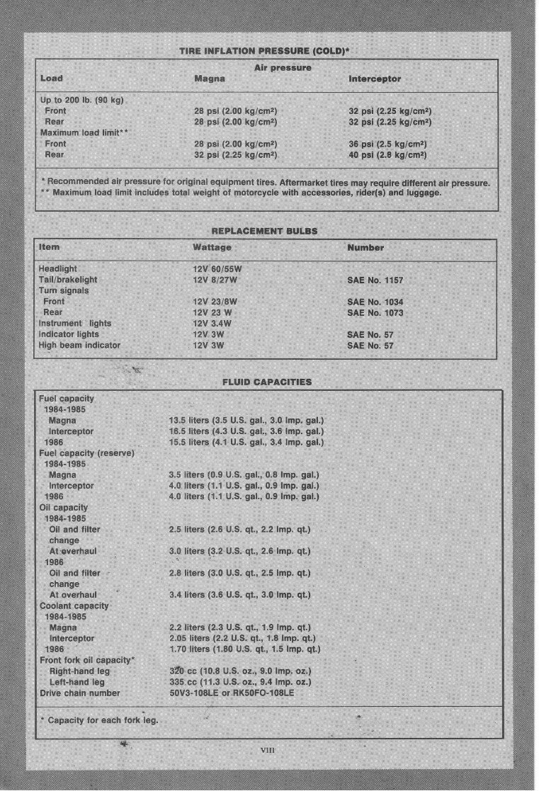
TrnE EffFLATION pRESSURE ICOLDI* Air pressure Load ftfiagna Interceptor up ro 200Ib. {9s }<g} Front Rear 2& psi {2.00 kg/cm2) 2E psi {2.S0 kg/cm:i ?S Bsi {2"00 kg/cmz) 32 psi (2.25kg/crn2) 32 psi (2,25 kg/cm2) 32 psi (2,25 kglcmz) 36 psi (2.5 kg/cmz) 40 psi (2.8 kg/cma; Maxirnum load Front Rear * Fleeommended air pressunefoil r*riglnaH equiprnent tires. Aftermarket tire$ may require different air pressure. * " Maximum ioad Nimdt includes tCItal weight of motorcycle with accessories,rider(s) and luggage. ftEPLACEMENT BULBS Ntem Headlight Taili brakelight Turn signals Front Rear Instrumeni lights Indicator lights High bearn indicatov lffattaEe Number SAE No. 1157 SAE No. 1034 SAE No. 1073 SAE No. 57 SAE No. 57 'i2v 60/55W 12V E/27W 1ftW 23/8W "r2v as w 12V 3.4W IAV 3W TzV 3W FLUID GAPACITIES Fuel capacity 1984-'t985 Magna tS.S Eiters {3.5 U.S" gal., 3.0 lmp. gal.) lnterceptor 1ffi,5 liters {4.3 ti.S. gal., 3.6 lmp. gal.) 1986 n5.5fiiters {4"1 U.S.gal., 3.4 lmp. gal.) Fuel capacity (resenve) 1S&4-1985 ltJlagna .3"5 liters {S.g tJ.$"gal,, 0.8 lmp. gal.} lnterceptor 4.{} ilitens {'!.X Ll"$.gal.,0.9 flmp. gal.) X986 4"frliters {X.1 LJ.S. gal., 0.9 lmp. gal.} OiN capacity 19S4-19S5 Oil and filter ?.S niters {2.6 U.$" qt., 2.2 lmp" qt.) change At,overhaui S.&litens {$"2 U.$. qt., 2.6 lmp. qt.) 1g86 Oil and filter 2.S liters {3"0 U.S.qt., 2.5 lmp. qt.) change ^ tl":*I1,1y1.^ 3"4 liters {3"s u"s. qt., 3.0 lmp. qt.} Goolant capacity 1984-X985 lVlagna 2.2 iiters {2.S U.S. qt., '!.9 lmp. qt.) Interceptor p"{}5 flit€rs (?.2 U"S.qt., 1.8 lmp. qt.) 1986 1.70 filters {1.80 [J.S. qt., 1.5 lmp. qt.] Front fork oil capacity" Right-handleg 3fS ee {'!0,S U.$. oz,, 9.0 Innp. oz.} Lett-handleg 3$5,ee {11.3 U.S" oz., 9.4 lmp. oz.) Drive ehain number SSVS-ISBLE or RK50FO-108LH . eapacity for each fork leg. Er,
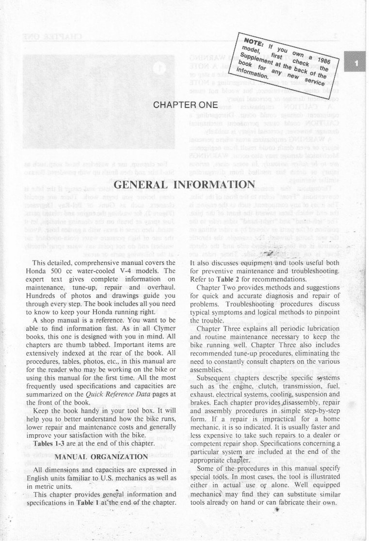
#*th oWr, -gr!ht^ 'rr-\-t crrec*' t986 tr^ - -.rtFrAa t-iuK tor '' cr the kk#; anv'i#"::',ff CHAPTER ONE GENERAL INFORMATION This detailed, comprehensive manualcovers the Honda 500 cc water-cooledV-4 models. The expert text gives complete information on maintenance, tune-up, repair and overhaul. Hundreds of photos and drawings guide you througheverystep. The book includes all you need to know to keepyour Honda running right. A shop manual is a reference. You want to be able to find information fast. As in all Clymer books,this one is designed with you in mind. All chapters are thumb tabbed. Important items are extensively indexed at the rear of the book. All procedures, tables, photos, etc.,in this manual are for the readerwho may be working on the bike or using this manual for the first time. All the most frequently used specifications and capacitiesare summarized on the Quick Reference Data pages at the front of the book. Keep the book handy in your tool box. It will help you to better understand how the bike runs, lower repair and maintenance costsand generally improve your satisfaction with the bike. Tables1-3 are at the end of this chapter. MANUAL ORGANiZATION All dimens'ions and capacities are expressed in English units farniliarto U.S. mechanics as well as in metric units. This chapter providesgene.?al information and specifications in Table I atthe:end of the chapter. -,'*&t -t' It also discusses eguipment and tools usefulboth for preventive maintenance and troubleshooting. Referto Table 2 for recommendations. Chapter Two provides.methods and suggestions for quick and accurate diagnosis and repair of problems. Troubleshooting procedures discuss typical symptoms and logicalmethods to pinpoint the trouble. Chapter Three explainsall periodic lubrication and routine maintenance necessary to keep the bike running well. Chapter Three also includes recommended tune-up procedures, eliminatingthe needto constantly consultchapters on the various assemblies. Subsequent chaptersdescribe specific gystems such as the engine, clutch, transmission, fuel, exhaust, electrical systems, cooling, suspension and brakes. Eachchapterprovides disassembly, repair and assemblyprocedures in . simple step-by-step form. If a repair is impractical for a home mechanic. it is so indicated. It is usually faster and lessexpensive to take such repairsto a dealeror competent repairshop.Specifications concerning a particular systemare included at the end of the appropriate chapier. Some of the.procedures in this manual specify special tools. In most cases, the tool is illustrated either in actual use of alone. Well equipped mechanicd' may find they can substitutesimilar tools alreadyon hand or can fabricate their own. ,t
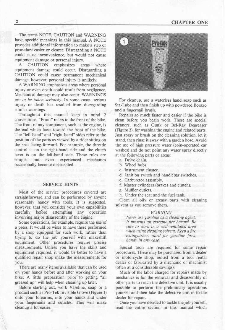
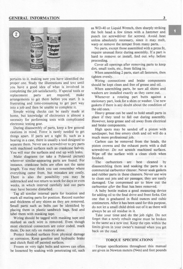
CHAPTER ONE The terms NOTE, CAUTION and WARNING have specific meanings in this manual. A NOTE provides additional information to make a step or procedure easier or clearer. Disregarding a NOTE could cause inconvenience, but would not cause equipment damageor personal injury. A CAUTION emphasizes areas where equipment damage could occur. Disregarding a CAUTION could cause permanent mechanical damage;however, personal injury is unlikely. A WARNING emphasizes areas where personal injury or even death could result from negligence. Mechanical damagemay also occur. WARNINGS are to be taken seriously. In some cases,serious injury or death has resulted from disregarding similar warnings. Throughout this manual keep in mind 2 conventions. "Front" refers to the front of the bike. The front of any component,such as the engine, is the end which faces toward the front of the bike. The "left-hand" and "right-hand" sides refer to the position of the parts as viewed by a rider sitting on the seat facing forward. For example, the throttle control is on the right-hand side and the clutch lever is on the left-hand side. These rules are simple, but even experienced mechanics occasionally becomedisoriented. SERVICE HINTS Most of the service procedures covered are straightforward and can be performed by anyone reasonably handy with tools. It is suggested, however, that you consider your own capabilities carefully before attempting any operation involving major disassembly of the engine. Someoperations, for example, require the useof a press.It would be wiser to have these performed by a shop equipped for such work, rather than trying to do the job yourself with makeshift equipment. Other procedures require precise measurements. Unless you have the skills and equipment required, it would be better to have a qualified repair shop make the measurements for you. There are many items available that can be used on your hands before and after working on your bike. A little preparation prior'to getting "all greased up" will help when cleaning up later. Before starting out, work Vaseline, soap or a product suchas Pro-Tek Invisible Glove (Figure 1) onto your forearms, into your hands and under your fingernails and cuticles. This will make cleanup a lot easier. For cleanup,use a waterless hand soap such as Sta-Lube and then finish up with powdered Boraxo and a fingernail brush. Repairs go much faster and easier if the bike is clean before you begin work. There are special cleaners, such as Gunk or Bel-Ray Degreaser (Figure 2),for washing the engine and relatedparts. Just spray or brush on the cleaningsolution, let it stand, then rinse it away with a garden hose. Avoid the use of high pressurewater (coin-operated car washes) and do not point any water spray directly at the following parts or areas: a. Drive chain. b. Wheel hubs. c. Instrument cluster. d. Ignition switch and handlebar switches. e. Carburetorassembly. f. Master cylinders (brakes and clutch). g. Muffier outlets. h. Under the seat and the fuel tank. Clean all oily or greasy parts with cleaning solvent as you remove them. WARNING Never usegasoline as a cleaning agent. It presentsan extreme fire hazard. Be sure to work in a well-ventilated area when using cleaningsolvent. Keep afire extinguisher, rated for gasoline fires, handy in any case. Special tools are required for some repair procedures. Thesemay be purchased from a dealer or motorcycle shop, rented from a tool rental dealer or fabricated by a mechanic or machinist (often at a considerablesavings). Much of the labor charged for repairs made by mechanics is for the removal and disassembly of otlrer parts to reach the defective unit. It is usually possible to perform the preliminary operations yourself and then take the defective unit in to the dealer for repair. Once you have decidedto tackle the job yoursell read the entire section in this manual which
GENERAL INFORMATION pertainsto it, making sure you have identified the proper one. Study the illustrations and text until you have a good idea of what is involved in completingthe job satisfactorily. If special tools or replacement parts are required, make arrangements to get them before you start. It is frustrating and time-consuming to get part way into a job and then be unable to complete it. Simple wiring checks can be easily made at home, but knowledge of electronics is almost a necessityfor performing tests with complicated electronictestinggear. During disassembly of parts, keep a few general cautions in mind. Force is rarely needed to get things apart. If parts are a tight fit, such as a bearing in a case, there is usually a tool designed to separate them. Never usea screwdriver to pry parts with machined surfaces such as crankcase halves. You will mar the surfaces and end up with leaks. Make diagrams (or take a Polaroid picture) wherever similar-appearing parts are found. For instance.crankcase bolts are often not the same length. You may think you can remember where everything came from, but mistakes are costly. There is also the possibility you may be sidetracked and not return to work for daysor even weeks, in which interval carefully laid out parts may have becomedisturbed. Tag all similar internal parts for location and mark all mating parts for position. Record number and thicknessof any shims as they are removed. Small parts such as bolts can be identified by placing them in plastic sandwich bags. Seal and label them with masking tape. Wiring should be taggedwith masking tape and marked as each wire is removed. Even though most electrical connectorsare color coded, mark them. Do not rely on memory alone. Protect finished surfaces from physical damage or corrosion. Keep gasoline and hydraulic brake and clutch fluid off painted surfaces. Frozen or very tight bolts and screws can often be loosened by soakingwith penetratingoil, such as WD-40 or Liquid Wrench, then sharply striking the bolt head a few times with a hammer and punch (or screwdriver for screws). Avoid heat unless absolutely necessary, since it may melt, warp or remove the temper from many parts. No parts,except thoseassembled with a press fit, require unusual force during assembly. If a part is hard to remove or install, find out why before proceeding. Cover all openings after removing parts to keep dirt, small tools, etc., from fatling in. When assembling2parts,start all fasteners, then tighten evenly. Wiring connections and brake components should be kept clean and free of grease and oil. When assembling parts, be sure all shims and washers are installed exactly as they came out. Whenever a rotating part butts against a stationarypart, look for a shim or washer. Use new gaskets if there is any doubt about the condition of the old ones. Heavy grease can be used to hold small parts in place if they tend to fall out during assembly. However, keep grease and oil away from electrical and brake components. High spots may be sanded off a piston with sandpaper, but fine emery cloth and oil will do a much more professional job. Carbon can be removed from the heads, the piston crowns and the exhaust ports with a dull screwdriver. Do not scratch machined surfaces. Wipe off the surface with a clean cloth when finished. The carburetors are best cleaned by disassembling them and soaking the parts in a commercialcarburetorcleaner. Never soakgaskets and rubber parts in thesecleaners. Never use wire to clean out jets and air passages; they are easily damaged. Use compressedair to blow out the carburetor after the float has been removed. A baby bottle makes a good measuringdevice for adding oil to the final drive and front forks. Get one that is graduated in fluid ounces and cubic centimeters. After it hasbeenused for this purpose, do not let a small child drink out of it as there will alwaysbe an oil residuein it. Take your time and do the job right. Do not forget that a newly rebuilt engine must be broken in the same as a new one. Keep the rpm within the limits given in your owner's manual when you get back on the road. TORQUE SPECIFICATIONS Torque specificationsthroughout this manual are given in Newton meters(N.m) and foot pounds ffi
You're Reading a Preview
What's Included?
Lifetime Access
Fast Download Speeds
Online & Offline Access
Access PDF Contents & Bookmarks
Full Search Facility
Print one or all pages of your manual
$30.99
1984-1986 Honda VF500C Magna VF500F Interceptor Service & Repair Manual
This Workshop Service Repair Manual provides comprehensive technical information necessary for performing all repairs on HONDA VF500C MAGNA VF500F INTERCEPTOR models from 1984 to 1986. It includes detailed repair procedures, easy-to-read exploded views, diagrams, illustrations, specifications, step-by-step instructions, and much more.
Whether you are a professional mechanic or a DIY enthusiast, this Workshop Repair Manual is essential for servicing, teardowns, repairs, overhauls, adjustments, and complete specifications. It is compatible with both PC and Mac, including various operating systems such as 95, 98, 2000, NT, XP, Vista, Windows 7, and 8.
With instant access in PDF format, this top-quality Workshop Manual is an invaluable resource for accurate identification, disassembly/re-assembly, and correct repairs.
Reviews
Q&A
Recently Viewed
5,521,897Happy Clients
2,594,462eManuals
1,120,453Trusted Sellers
15Years in Business
Price:
Actual Price:
1984-1986 Honda VF500C Magna VF500F Interceptor Service & Repair Manual



 Lifetime Access




