Honda 50 c 100 c 102 c 110 c 114 Service Repair Manual
What's Included?
Lifetime Access
Fast Download Speeds
Offline Viewing
Access Contents & Bookmarks
Full Search Facility
Print one or all pages of your manual
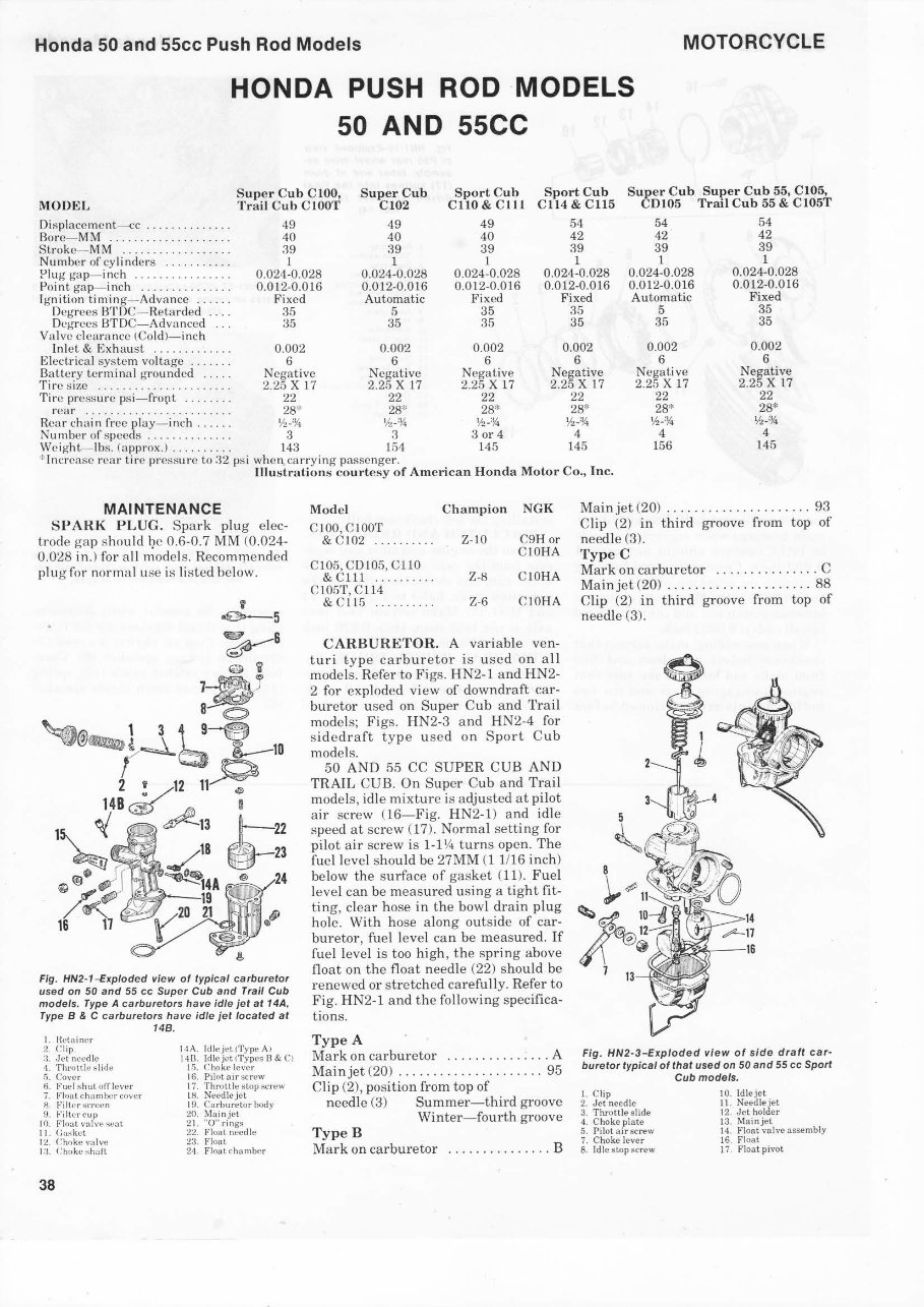
Honda 50 and 55cc Push Rod Models MOTORCYCLE HONDA PUSH ROD MODELS 50 AND 55CC MODEL Super Cub C lOO, Trail Cub Cl OOT Super Cub C 102 Sport Cub CliO & C lll Sp ort Cub Cll4 & C ll5 S u8 er Cub Supe r Cub 55, C105, 0105 Trail Cub 55 & C105T 49 49 49 54 54 54 40 40 40 42 42 42 Displaccmenl--<:c ............. . Do rc- MM . . ... . .... .. .... .. . . Stroke- MM ........ . ....... . . 39 39 39 39 39 39 Nu mbc r of cy li ndcrs . . . ..... .. . 1 1 1 1 1 1 Plug ga p- inch ............... . 0.024-0.028 0.024-0.028 0.024-0.028 0.024-0.028 0.024-0.028 0. 02 4-0.028 Point gap-inc h .............. . 0. 0 12-0.0 16 0.012-0.016 0.012-0.016 0.012-0.016 0.012-0.016 0.012-0.016 lgn ition ti ming- Ad va ncc ..... . Fix cd Automat ic Fixed Fi xcd Automatic Fi xed 35 5 35 35 Degrecs BTDC- Retarded ... . Dcg-rees BT DC-Advanced .. . Valve clcar·ance (Cold)-inc h In lel & . . . . . . . . . . . . . 0.002 0.002 Elcclrical syslem vollage . . . . . . . 6 6 term inal groundcd . . . . . Ncgat ivc Negative r11· c S IZC .. .. .. .. .. .. .. .. .. .. .. 2.25 X 17 2.25 X 17 Tire prcssu re psi-f r ort . . . . . . . . 22 22 rcar . . . . . . . . . . . . . . . . . . . . . . . . 28* 28* H ea r eh ai n frcc pl ay - inch . . . . . . Yl-'14 y, . '!(. Numbcr of speeds . . . . . . . . . . . . . . 3 3 Wc i l{ht- lbs. (a pprox.) . . . . . . . . . . 143 154 : lncrcasc rcar ti re pr cssurc to 32 psi when carrying pas scngcr. 35 35 0.002 6 Ncgative 2.25 x 17 22 28* Yl-% 3 or 4 14/i 35 35 0.002 6 Negative 2.25 x 17 22 28* 'h-% 4 145 5 35 0.002 6 Ncgative 2.25 x 17 22 28* 'h-% 4 156 35 35 0.002 6 Negative 2.25 x 17 22 28* Yl -:Y.. 4 145 lllu strations c ourtcsy of Amcri ca n Ho nda Motor Co., Inc. MAINTENANCE SPARK P LUG. Spar k pl ug elec- lt·ode gap should l] e 0.6-0.7 MM (0.02 4- 0.028 in.) for all model s. Recoml]1ended plu g f or normal use is li stc d bclow. Fig. HN2- 1-Exploded view of typical carb uretor used on 50 and 55 cc Super Cub and Trai/ Cub mode Is. Type A carb u retors have I di e jet at 14A, Typ e 8 & C ca rbure t ors h ave ldle jet loca ted at I. Hl•l ainu Chp -l et needie l. Throu!c !l ( 'ov('r 6. Fut •I :;hut oiTlever 7. F1lll'r scrct.•n !J . F1ltcr cup 10. vulvt• 11. (;askct 14!. ('hnkc volvc I :1. ( 'ho kc 38 148. I IA. ldleJ•toType Al B & Cl 16. Pilot aar 17. Thruttlc s topscrew tR N'ecdle jet I9 C'orbur•tor body MolnJCt ... 0" rings Float needie Float 24 . Flout eh amber Model Cha mp ion NGK C100,ClOOT & C 1 02 .......... Z- 10 C9H or ClOHA C105,CD IOfi,C110 & Clll ..... . .... Z-8 C 10 HA C105T, CI I4 &CII5 . ... · ··· ·· Z-6 C10HA C ARBURE TOR. A var iabie ven- t ur i t ype carb u retor is used on a ll mode Is. Refer to Figs. HN2 -l and HN2- 2 for exploded vi ew of downd raft car- buretor u se d on Sup er Cub and Tra il modcls; Figs. HN2-3 and HN2-4 for sidcdraft type u scd on Sport Cu b mode Is. 50 AND 55 CC SUPE R CUB AND TRAIL CUB. On Super Cub a nd Trail mode Is, idle mixt ure is adjusted at pilot a ir scr ew (16- Fig. HN2-1) and idle speedalsc r ew (17). Nor ma l setti ng for pilot ai rsc rew is 1-1 Y<l tu rns open. The fuel level should he 27MM (1 1/16 in ch ) below the surface of gas ket ( 11). Fuel leve l can be meas ured using a tight fit- ting , clear hose in the bowl dra in plug hole. With hose along outsi de of ca r- bur etor, fuel level can be measured. If fuel level is too h igh , t he spring above float on the fl oat need ie (22) sh ould be rencwed or str etc hed ca r ef ull y. Refer to Fig. HN2 -1 and the following specifica- ti ons. Type A Mark on carburetor .. .. . .......... A Mainjet (20) .. . .................. 95 Clip (2), position fr om top of needie (3) Su mmer -t hird groove Win ter- fo urth gr oove TypeB Ma rk on carburetor . . ............. B Mainjet (20) ..................... 93 Clip (2) in third groove from top of needie (3). TypeC Mar k on carbur etor . ............ . . C Mai njct (20) .............. . .... .. 88 Clip (2) in thi rd groove from top of needie (3) . 5 Fig . HN2 -3-Explod ed view of s/ do dra ft car- bure tor typ/cal of that used on 50 and 55 cc Sport Cubmodels . 1. Clip 2. Jet needie 3. Throttle slide 10. ldlejet g 4. Choke plate 5. Pîlot airscrew 7. Choke lever 13. 14. Float valve nssembly 16. Float 8. !die stopscrew 17. Float pivot
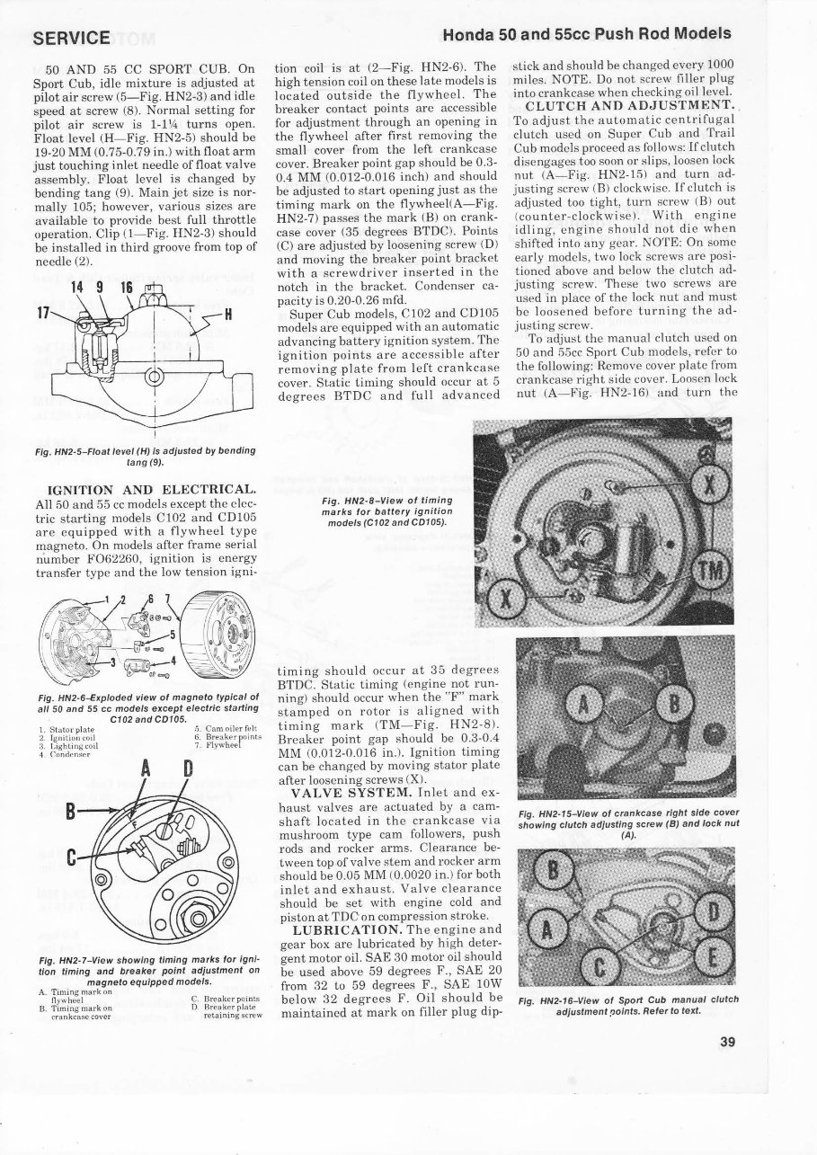
SERVICE 50 AND 55 CC SPORT CUB. On Sport Cub, idle mixture is adjusted at pilot airscrew (5-Fig. HN2-3 ) and idie speed at screw (8). Normal se tting for pil ot air screw is 1-1 \4 turns open. Float level (H-Fig. HN2-5) s hould be 19-20 MM (0.75-0.79 in.) with float arm just touching in l et need ie of float va lve assembly. Float l eve l is changed by bendin g tang (9). Ma in jet size is nor- mally 105; however, various sizcs are avai la bl e to provide best full throttle operati on. Clip (1-Fig. HN2-3) s hould be ins talled in th ird groove from top of need ie (2). Fig. HN2·5-Fioat level (H) is adjusted by bending tang(9). IGNITION AND ELECTRICAL. All 50 and 55 cc models except the e lec- tric sta rting models Cl02 and CD105 are e quipp ed wit h a flywheel type magn eto. On models after frame se rial number F062260, ig nition is ener gy transfer type a nd the low tens ion igni- Fig. HN2·6-Exploded view of magneto typical of all 50 and 55 cc models except electric starting C102 and CD105. 1. Stator plate 2. lgn1tion coil 3. l.ighlinj.jcoil 4. Condcnse r 5. Cam oller feit 6. Breaker points 7. A D Fig. HN2·7-View showing timing marks for igni· tion timing and breaker point adjustment on magneto equipped models. A. T iming mark on n ywheel B. Timin g mark on crankcase cover C. Bre aker points D. Brcaker pl ate retain ing screw Honda 50 and 55cc Push Rod Models tion coil is at (2-Fig. HN2-6). The high tension coil on these la temodels is located outside the fl yw heel. The breaker contact points are accessible for adjustment through an opening in the fl ywh ee l after fir st removing the s mall cover from the left crankcase cover. Br ea ker point gap should be 0.3- 0.4 MM (0.012-0.016 inch) and shou ld be adjusted to sta rt openingjustas the ti ming mark on the fl ywhee l{ A- Fi g. HN2-7 ) pas ses the mark (B) on cra nk- case cover (35 degrees BTDC). Poin ts (C) are adjusted by loosen ing screw (D) a nd rnaving the breaker po int bra cket w ith a sc rewdriv er in se rted in the notch in the brac ket. Conden se r ca- pacity is 0.20-0.26 mfd. Super Cub model s, C l0 2 and CD105 models are equipp ed with an automatic advancing batt ery ignition sys tem . The ignition point s ar e acc ess ible after removing pl ate from l eft crankcase cover. Static timing should occur at 5 degre es BTD C and full advanccd Fig. HN2-8-View of timing marks for battery ignition models (C102 and CD105). timing sho uld occ ur at 35 degrees BTDC. Static timing (eng ine not run- nin g) should occ ur when the "F" mark s tamp ed on r oto r is a lig ned with ti ming mark (TM-F ig. HN 2-8). Ereaker point gap should be 0.3-0.4 MM (0.012-0.016 in.). Ig nition timing ca n be cha nged by moving stator pl ate after loose nin g scr ews (X). V ALVE SYSTEM. In l et a nd ex - haust valves are a ctu ate d by a cam- s haft l ocated in the cran kc ase via mus hroo m type cam followers, push rods and rocker a rms. Cl ea rance be- tween top of valve s tem and rocker arm shou ld be 0.05 MM (0.0020 in.) for both inlet a nd ex hau st. Valve clearance should be set with e ng i ne cold a nd pis ton at TDGon co mpre ss ion s troke. LUBRICATION . Th e e n gi ne a nd gear bo x are Jubri cated by high dete r- gent motor oil. SAE 30 motor oil should be used above 59 d egrees F., SAE 20 from 32 to 59 deg rees F ., SAE lOW below 32 degree s F . Oil s hould be maintained at mar k on filler plug dip- stick and should be changed every 1000 miles. NOTE. Do not screw Iilier plug into crankcase when check i ng oillevel. CLUTCH AND ADJUSTMENT. To a dju st the automatic eentr i fuga! clutch used on Super Cu b a nd Trail Cub mode Is praeeed as fol lows: If clut ch disengages too soon or slips, loosen loek nut (A- Fig. HN2-15) a nd t urn a d- justing sc rew (B) clockwise. l fclutch is adjus ted too tight, turn scrcw {B) out (c ounter-c l ockwi se). With engine id ling, cn gi ne s hould nol die whcn s hif ted into any gca r. NOTE: On some ear ly models, two loek scr cws a re posi- tioned above an d below the clu tch ad- justing screw. These two sc rews are used in place of the loek nut a nd mu st be loo se n ed befare turnin g the ad- justing screw. To adjust the manual clutch used on 50 a nd 55cc Sport Cub model s, ref er to the followin g: Remave cover pla te from cra nkc ase right si de cover. Loosen loek nut (A-Fig. HN2-16) and turn the Fig. HN2·15-View of crankcase right s/de cover showing clutch adjusting screw (B) and loek nut (A). Fig. HN2·16-View of Sport Cub manual clutch adjustment points. Refer to text. 39
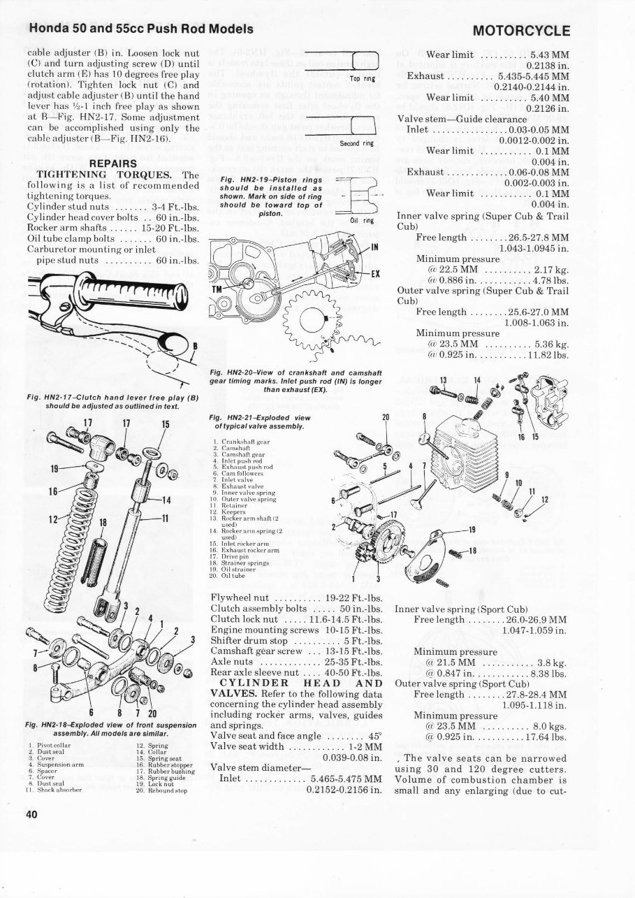
Honda 50 and 55cc Push Rod Models eable adjustcr (8 ) in. Loosen l oe k nut (Cl and turn serew (0) until cluteh arm (E) ha s LO degrees frce play (rotati on). Ti g htcn loek nut (C) and adju st eablc adju ster ( 8) until the hand l eve r has i neh f1· ee play as at B- Fig. HN2- 17 . Some adjust ment ca n be accomp li shcd using only the ca bl c adjuster ( B- Fi g. HN2- 16). REPAIRS TIGHTENING TORQUES. The fo llowing is a list of rcco mmended tightening torqucs. Cylinder nuts ....... 3-4 Ft.-Ibs. Cy li nder h ea d cover bolts .. 60 in.-Ibs. Roc ker arm s hafts ...... 15-20 Ft.-Ibs. Oi l tube cla mp bo lts .... . .. 60 in.-lbs. Carbur ctor mou n ting or i niet pi pc s tud n uts .......... 60 i n .- lb s. I ' I .......__", --,... Fig . HN2·17 -Ciut ch hand lev e rfr ee pl ay ( B) should be adjusted as o utlin ed in text. Fig. HN2-18-Exploded view of front su spe nsion assembly . All models are slm/lar. I. Pivot collar Ou.st sea l Cover 4 Su!oipcnsion a rm 6. Spaeer 7. Cover H. Tlu'ilseal 11 . Shock absorbcr 40 12. Spring 14. Collar 15. Spring sent 16 . Rubber stopper 17. Rubber bushing 18. Sprin g guide 19. Loek nut 20. Re bo und stop Fig . HN2- 19-Pisto n rings sho uld be in sta ll ed as shown. Mark on side of ring should be toward top of piston. ( ) Top nnc ( \ Socond ring Ooi ring Fig. HN2-20-View of cranksh aft and camshaft gear timing marks. /niet push rod (IN) is longer than exha ust (EX). Fig. HN2-21-Exploded view of typica/ valve assembly. l. gear Cumtthan 3. Cams han gear 4. I n let push rod !i Ex ha us t p ush rod 6. Cnm followers 7. In h.•t valve H. valve 9. Inner valve spring 10. Outer val ve s pring 11. Het ai ncr Keepers 13. Ruck er arm sha f\. (2 uscdl 14. Rocker turn spring tl usedl 15. I niet rockerarm 16 . rocker arm 17 . Drive pin 18. Strainer springs 19. Oil st rainer 20. Ooitube 3 20 Flywheel nut .. .... . ... 19-22 Ft.-lbs. Clutch assembly bolts ..... 50 in.-Ibs. Clu tch loek nut ..... 11.6-14.5 Ft.-lbs. Engine mounting screws 10-15 Ft .-Ibs. Shifter drum stop ... . ... .. . 5 Ft .-Ibs. Ca ms haft gear scr ew ... 13-15 Ft.-lbs. Axl e nuts ........ .. ... 25-35 Ft .-Ibs. Rear axle sleeve nut ... . 40-50 Ft.-lbs. CYL INDER HEAD AND V ALVES. Refer to the following data conce rning the cylinder head assembly including rocker arms, valves, guides and springs. Valve sca t and face angle ........ 45 ° Valve sca t width .. .. .. . ..... 1-2 MM 0.039-0.08 in . Valve stem diameter- Inlet ............. 5.465-5.475 MM 0.2152-0.2156 in. MOTORCYCLE Wear limit ......... . 5.43 MM 0.2138 in. Exhaust . . . . . . . . . . 5.435-5.445 MM 0.2140-0.2144 in. Wear limit .......... 5.40 MM 0.2126 in. Valve stem- Guide cl earance In let ......... . .. . ... 0.03-0.05 MM 0.0012-0.002 in. Wear limit ........... 0.1 MM 0.004 in . Exhaust ............. 0.06-0.08 MM 0.002-0.003 in. Wear limit ... . .. .. ... 0.1 MM 0.004 in . Inn er va lve spring (Super Cub & Trail Cub) Fre e length ........ 26.5-27.8 MM 1.043-1.0945 in . Minimum pres s ure (c1 22.5 MM .. ...... .. 2.17 kg . (ct 0.886 in .......... .. 4.78lbs. Outer valve s pring (Super Cub & Tr ail Cub) Free le ngth ........ 25.6-27.0 MM 1.008-1.063 in. Minimum pressu re (11 23.5 MM .......... 5.36 kg . (11 0.925 in ........... 11.82 1bs. Inner valve s pring (Sport Cub) Free length ........ 26.0-26.9 MM 1.047-1.059 in . Minimum press ure (a 21.5 MM ........... 3.8 kg. (é_ t 0.847 in ............ 8.38lbs. Outer valve spring (Sport Cub) Free length ........ 27.8-28.4 MM 1.095-1.118 in. Minimum pr essure @ 23.5 MM ........ .. 8.0 kgs. @ 0.925 in ......... . . 17.64 lbs. . The va l ve seats can be narrowed us ing 30 and 120 degree cutters. Volume of combustion chamber is sma ll and any en larging (due to cut-
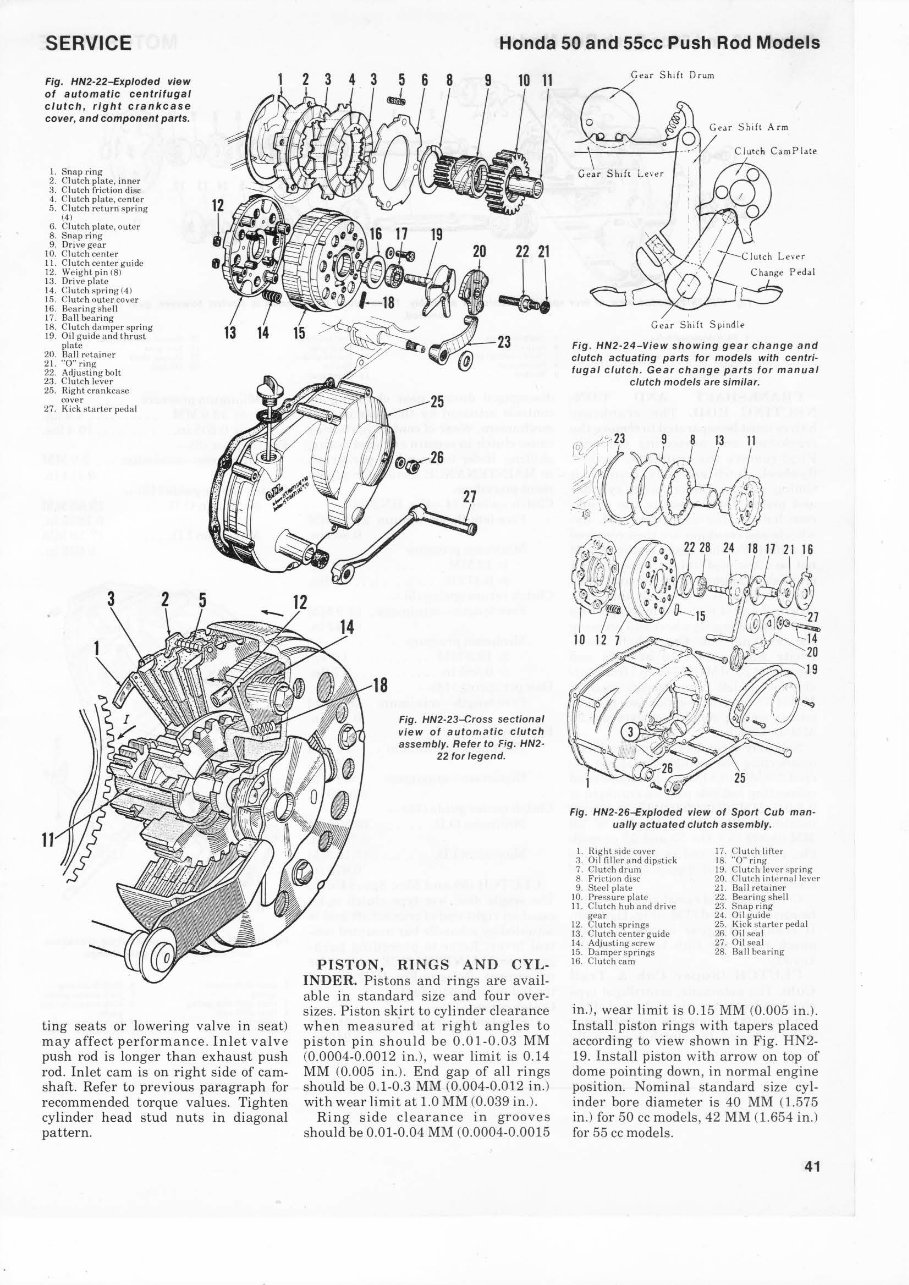
SERVICE Fig. HN2-22-Exploded view of automatic centrifuga/ clutch , right crankcase cover, and component parts. l. Snap ri ng 2. Clutch platc, inner 3. Cl utch friction disc 4. Cl utch platc, center 5. Clut ch return s pring (4 ) 6. Clutch plate. outer 8. Snap ri ng 9. Ori ve ge ar 10. Clutch ce nter ll. Clutch center g uide 12. Weig ht pin (81 13. Drive plate 14. Clutch s pring (4) 15. Clutch oute r co ver 16. Bcaring s hell 17. Bali hearing 18. Clutch damper sprin g 19. Oil guidc and thrust plate 20. Rail rctainer 21. " 0" ring 22. Adjus ting bolt 23. Clutch lever 25. Right crankca se (:o ver 27. Kick starter peda! 11 13 14 ting seats or lo wering valve in seat) may affect performance. Inl et valve push rod is longer than exha ust push rod. Inlet cam is on right side of cam- shaft. Refer to previous paragraph for recommended torque va lue s. Tighten cylinder head stud nuts in diagonal pattern. Honda 50 and 55cc Push Rod Models 2 3 4 3 15 18 8 9 10 11 Fig. HN2-23-Cross sectional view of automatic clutch assembly. Re ter to Fig. HN2- 22 tor legend. PISTON , RINGS AND CYL- INDER. Pi stons and rings are avail- able in standard size and four over- sizes. Pi stonskirt to cylinder clearance when measured at right angles to piston pin shou ld be 0.01-0.03 MM (0.0004-0.0012 in.), wear limi t is 0.14 MM (0.005 in.). End gap of all rings should be 0.1-0.3 MM (0.004-0.012 in.) with wear limit at 1.0 MM (0.039 in.). R ing side clearance in grooves sho uld be 0.01-0.04 MM (0.0004-0.0015 Gear Sh i lt Drum Ge ar Shift S pond ie Fig . HN2-24 -Vie w showing gear c hange and clutch actuating parts tor models with ee ntri- tugal clutch. Gear c hange parts tor manual clutch models are similar. Fig. HN2-26-Exploded view of Sport Cub man- ually ac tuated clutch assembly. I H1g ht sidt! cover Ooi fillcr and di pstick 7. Clutch drum 8. Friction disc 9. Steel plate 10. Pressurc platc 11. Clut ch hub and drive gear 12. Clutch springs 13. Clutch cen ter gu idc 14 . Adj usting screw l5. Damper s prings 16 . C lutch ca m 17. Clutch lillor 18. " 0 " ri ng 19. Clutch lever 20. Cl utch inlcrnal lcvcr 21. Bali retainer l2. Bearin g shel l 23. Snap ri ng 24. Oil guide 25. Kick slarler peda! 26. Oil sea l 27. Oi l seal 28. Bali bearing in.), wear limit is 0.15 MM (0.005 in.). Install piston rings with tapers placed according to view shown in Fig. HN2- 19. Install piston with arrow on top of dome pointing down, in normal eng in e position. Nomi na! s tandard size cyl- inder bore diameter is 40 MM (1 .575 in.) for 50 cc models, 42 MM (1.654 in.) for 55 cc models. 41
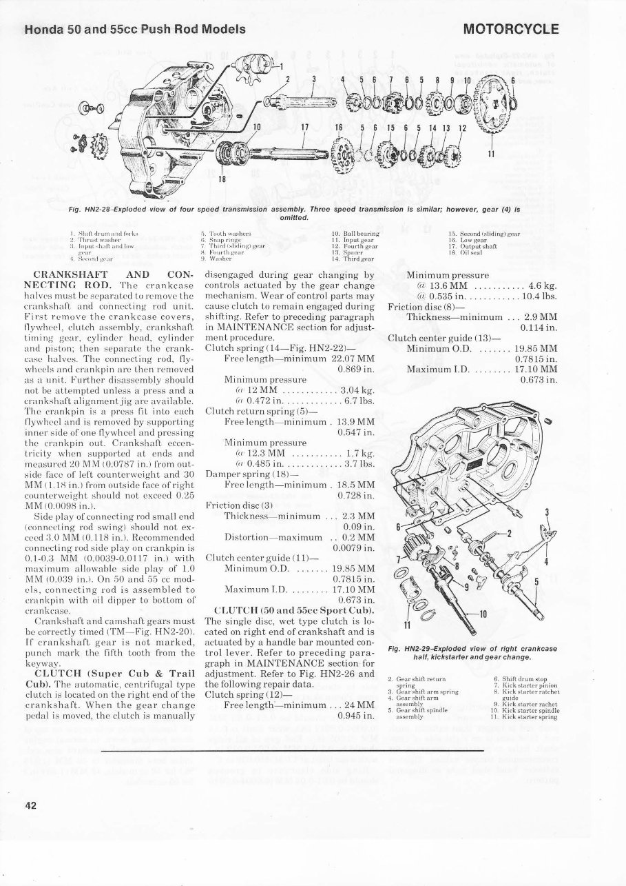
Honda 50 and 55cc Push Rod Models MOTORCYCLE Fig. HN2-28-Exploded view of four spee d transmission assembly. Three speed transmission is similar; however, gear (4) is omitted. I. Shill dnun and fi11·ks l. Thru!'>t waslu.•r :1. Input :-;hall. nnd low g"t':l f t. S.•cond J..;"('ilf CRANKSHAFT AND CON- NECTING ROD. Th e crankcase halves must be scpa raled lo remove lhe crankshaft and connecling roei unit. Fir st remove lhe crankcase covers, flywheel, clulch assemb ly, crankshaft timing gear , cylinder llCad, cy linder and piston; Lhen se parate lh e crank- case ha lves. The conneding roei, fl y- wheels and crankpin are then removed as a unit. Further disassembly shou ld not be alternpled unle ss a press and a crankshaft al ignmenljig me available. Th e crankpin is a prcss fit into eac h fl ywhecl and is removed by s upporling inner si de of one fl ywhec l a nel pressing lhe c rankpin out. Crankshaft ecce n- lricily when sup potted at enels and measurcd MM (0.0787 in.) from out- siele face of left counlerweight and 30 MM ( l.1H in.) fnHn outsiele face ofrighl counterweight shou ld nol exceed 0.25 MM (0.0098 i n.l. Siele play of conneetingroei small end (connccling roei swing) shou ld not ex- ceed 3.0 MM (0.118 in.). Reeomme ndeel con necting roei side play on crankpin is 0.1-0.3 MM (0.0039-0.0117 in.) with maximum allowable side play of 1.0 MM (0.039 in.). On 50 and 55 cc moel- els , connecling r oei is assembied to crankpin with oil clipper lo bollom of crankcase. Crankshaftand camshaft gears mu st be correctly timed (TM - f ig. HN2-20 ). rr crankshaft gea r is n ol marked , punch mark the fifth looth fwm the keyway. CLUTCH (Supe r Cub & Tt·ail Cub). Th e automatic , centrifugal type clutch is lo cated on the rig ht end ofthe crankshaft. When t he gear change peelal is moved, lhe dulch is manually 42 !'"t. Touth washL'I'S ()_ Snap ri ngs 7. Third fsliding-) gcar H. Fuu r t h g._•ar 9. Washer 10. I3all hcarin,:r 1 I. Input gca r 12. Fuurth gear 13 . S paeer 14. Third gear clisengaged during gear changing by contro ls actualed by lhe gear change mechani s m. Wear of control parts may ea u se cl utch to re ma in engaged duri ng shifling. Refer lo preceding paragraph in MAINTENANCE secl ion for acljust- ment procedure. Clutch spr ing 04- Fig. HN2-22 )- Free length- minimum 22.07 MM 0. 869 in. Minimum pressure (a 12 MM ... ... ...... 3.04 kg. (i r 0.472 in ............. 6.7lbs. Clulch relurn s pring (5)- Free lenglh- minimum. 13.9 MM 0.547 in. 'Minimum pre ssu re (u 12.3 MM ........... 1.7 kg. (ir 0.485 in .... . .. .. .... 3.7lbs. Damper sp ring ( 18)- Free len glh-mi nimum . 18.5 MM 0.728 in. Friction di se (3) Th ickness-mi nimurn Di slo rtion - maximum Clutch center g uide (11)- 2.3MM 0.09 in. 0.2MM 0.0079 in. Minimum O.O ........ 19.85 MM 0.7815 in . Maximum I.O .. ... .... 17.10 MM 0.673 in. CLUTCH (50 and 55cc SpOI"t Cub). The s ingle clisc, wet type clutch is lo- cated on right end of crankshaftand is actuated by a handle bar mounted con- trol l ever. Refer to precedi ng para- graph in MAINTENANCE section for adjustment. Refer to Fig. HN2-26 and the following repair data. Clutch s pring (12 )- Free l engtb-min imum ... 24 MM 0.945 in. 15. Second (sliding) gcar 16. l.nw gcar 17. Outputshaft 18 . Oil scal Minimum press ure (iv 13.6 MM .. .. ....... 4.6 kg. (iL 0.535 in ......... . .. 10.4 lbs. Friction di se (8)- Thickness-minimum ... 2.9 MM 0.114 in. Clutch center guide (13)- Minimum O.D. . ... . .. 19.85 MM 0.7815 in. Max imum I.D ..... .. .. 17.10 MM 0.673 in. Fig. HN2-29-Exploded view of right crankcase half, kickstarter and gear change. 2. Gear shift return s pring 3. Gcar s hift arm s pring 4. Gear sh ift arm assemb ly 5. Gcar sh ift spi ndie assembly 6. Shift drum stop 7. Kick sta rter pinion 8. Kick starter ratche t. 9. rachet 10. Kick s tar ter spindie 11. Kick sta r ter spri ng
This is a highly detailed factory service repair manual for the Honda 50 c 100 c 102 c 110 c 114. It provides step-by-step instructions and detailed illustrations, making it suitable for both do-it-yourself enthusiasts and experienced mechanics. The manual covers general information, frame/body panels/exhaust system, maintenance, lubrication system, cooling system, fuel system, engine removal/installation, cylinder head/valve, clutch/gearshift linkage, alternator/starter clutch, crankcase/transmission, crankshaft/piston/cylinder, front wheel/suspension/steering, rear wheel/suspension, hydraulic brake, battery/charging system, ignition system, electric starter, lights/meters/switches, wiring diagram, troubleshooting, and index.
This manual is known by various names, including Honda 50 c 100 c 102 c 110 c 114 Service Manual, Honda 50 c 100 c 102 c 110 c 114 Repair Manual, Honda 50 c 100 c 102 c 110 c 114 Workshop Manual, and Honda 50 c 100 c 102 c 110 c 114 Service Repair Manual. It is available in a printable format that is compatible with all PC-based Windows operating systems and Mac. The manual is instantly accessible, saving on postage and packaging costs.
Language: English
File Format: PDF
Requirements: Adobe Reader
Specifications: Fully Printable & Bookmarked
Compatible: All Versions of Windows & Mac, APP ISO, iPhone, iPad, Android, etc.
It is important to have the right repair manual for your Honda 50 c 100 c 102 c 110 c 114, as it will save you money and provide valuable insights into your vehicle. All pages of the manual are printable, ensuring easy access to the information you need.
Recently Viewed
5,521,897Happy Clients
2,594,462eManuals
1,120,453Trusted Sellers
15Years in Business
Price:
Actual Price:
Honda 50 c 100 c 102 c 110 c 114 Service Repair Manual