

2001-2010 Honda Gold Wing GL1800/GL1800A OEM Service & Repair Manual
What's Included?
Fast Download Speeds
Online & Offline Access
Access PDF Contents & Bookmarks
Full Search Facility
Print one or all pages of your manual
HOW TO USE THIS MANUAL
This service manual describes the service procedures for the GL1800/
GL1800A.
Follow the Maintenance Schedule (Section 3) recommendations to
ensure that the vehicle is in peak operating condition and emission levels
are within the standards set by the California Air Resources Board
(CARB).
Performing the first scheduled maintenance is very important. It
compensates for the initial wear that occurs during the break-in period.
Sections 1 and 3 apply to the whole motorcycle. Section 2 illustrates
procedures for removal/installation of components that may be required
to perform service described in the following sections.
Sections 4 through 22 describe parts of the motorcycle, grouped
according to location.
Find the section you want on this page, then turn to the table of contents
on the first page of the section.
Most sections start with an assembly or system illustration, service
information and troubleshooting for the section. The subsequent pages
give detailed procedures.
If you don't know the source of the trouble, go to Section 24,
Troubleshooting.
Your safety, and the safety of others, is very important. To help you
make informed decisions we have provided safety messages and
other information throughout this manual. Of course, it is not
practical or possible to warn you about all the hazards associated
with servicing this vehicle. You must use your own good judgement.
You will find important safety information in a variety of forms
including:
• Safety Labels – on the vehicle
• Safety Messages – preceded by a safety alert symbol and
one of three signal words, DANGER, WARNING, or CAUTION.
These signal words mean:
You WILL be KILLED or SERIOUSLY
HURT if you don’t follow instructions.
You CAN be KILLED or SERIOUSLY HURT
if you don’t follow instructions.
You CAN be HURT if you don’t follow
instructions.
• Instructions – how to service this vehicle correctly and safely.
As you read this manual, you will find information that is preceded by a
symbol. The purpose of this message is to help prevent
damage to your vehicle, other property, or the environment.
ALL INFORMATION, ILLUSTRATIONS, DIREC-
TIONS AND SPECIFICATIONS INCLUDED IN
THIS PUBLICATION ARE BASED ON THE LAT-
EST PRODUCT INFORMATION AVAILABLE AT
THE TIME OF APPROVAL FOR PRINTING.
HONDA MOTOR CO., LTD. RESERVES THE
RIGHT TO MAKE CHANGES AT ANY TIME
WITHOUT NOTICE AND WITHOUT INCURRING
ANY OBLIGATION WHATSOEVER. NO PART OF
THIS PUBLICATION MAY BE REPRODUCED
WITHOUT WRITTEN PERMISSION. THIS MAN-
UAL IS WRITTEN FOR PERSONS WHO HAVE
ACQUIRED BASIC KNOWLEDGE OF MAINTE-
NANCE ON HONDA MOTORCYCLES, MOTOR
SCOOTERS, OR ATVS.
HONDA MOTOR CO., LTD.
SERVICE PUBLICATIONS OFFICE
CONTENTS
GENERAL INFORMATION
FRAME/BODY PANELS/EXHAUST
SYSTEM
MAINTENANCE
LUBRICATION SYSTEM
FUEL SYSTEM
(Programmed Fuel Injection)
ENGINE AND DRIVE TRAIN
COOLING SYSTEM
ENGINE REMOVAL/INSTALLATION
CYLINDER HEAD/VALVES
CLUTCH
GEARSHIFT LINKAGE/TRANSMISSION
CYLINDER/PISTON/CRANKSHAFT
FINAL DRIVE
FRONT WHEEL/SUSPENSION/
STEERING
REAR WHEEL/SUSPENSION
BRAKE SYSTEM (Standard)
BATTERY/CHARGING SYSTEM
IGNITION SYSTEM
STARTER/REVERSE SYSTEM
LIGHTS/METERS/SWITCHES
CRUISE CONTROL SYSTEM
AUDIO SYSTEM
WIRING DIAGRAMS
TECHNICAL FEATURES
TROUBLESHOOTING
CHASSIS ELECTRICAL
24
23
22
21
20
19
18
17
16
15
14
13
12
11
10
9
8
7
6
5
4
2
3
1
Date of Issue: August, 2002
©HONDA MOTOR CO., LTD.
25
INDEX
BRAKE SYSTEM (ABS)
26
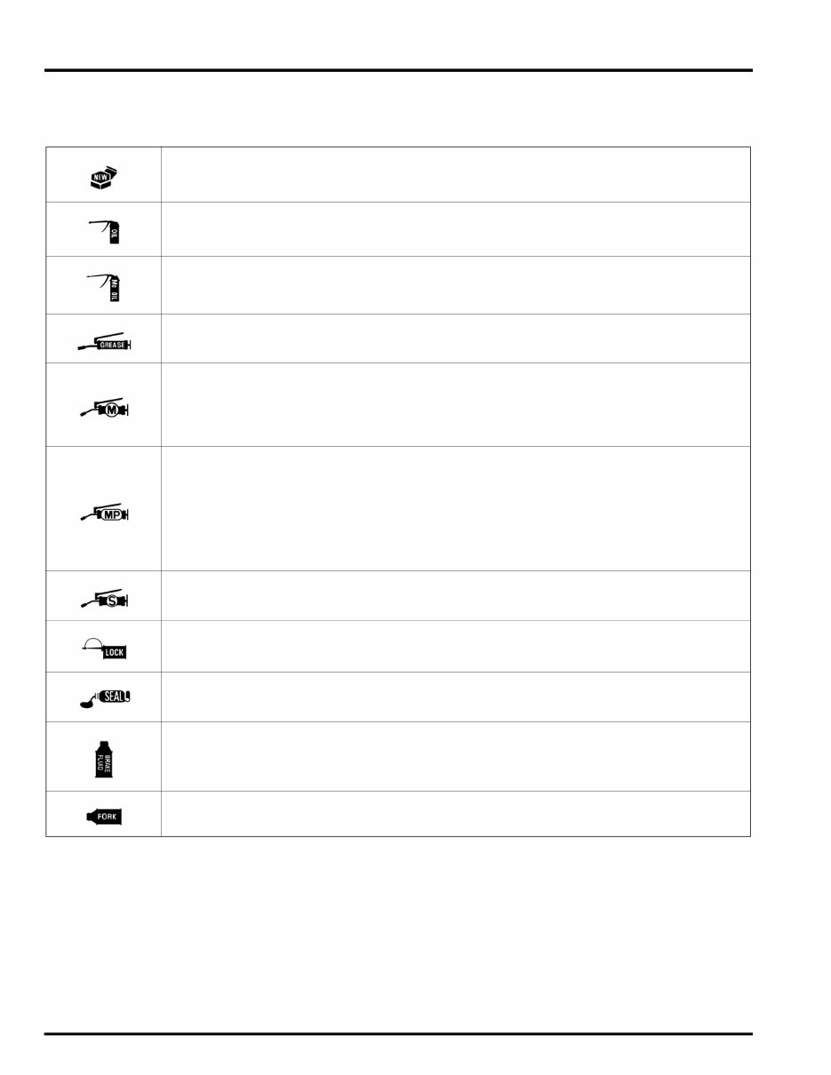
SYMBOLS
The symbols used throughout this manual show specific service procedures. If supplementary information is required pertaining to
these symbols, it would be explained specifically in the text without the use of the symbols.
Replace the part(s) with new one(s) before assembly.
Use recommended engine oil, unless otherwise specified.
Use molybdenum oil solution (mixture of the engine oil and molybdenum grease in a ratio of 1:1).
Use multi-purpose grease (lithium based multi-purpose grease NLGI #2 or equivalent).
Use molybdenum disulfide grease (containing more than 3% molybdenum disulfide, NLGI #2 or
equivalent).
Example: Molykote
®
BR-2 Plus manufactured by Dow Corning, U.S.A.
Multi-purpose M-2 manufactured by Mitsubishi Oil, Japan
Use molybdenum disulfide paste (containing more than 40% molybdenum disulfide, NLGI #2 or
equivalent).
Example: Molykote
®
G-n Paste manufactured by Dow Corning, U.S.A.
Honda Moly 60 (U.S.A. only)
Rocol ASP manufactured by Rocol Limited, U.K.
Rocol Paste manufactured by Sumico Lubricant, Japan
Use silicone grease.
Apply a locking agent. Use a medium strength locking agent unless otherwise specified.
Use sealant.
Use DOT 3 or DOT 4 brake fluid. Use the recommended brake fluid unless otherwise specified.
Use fork or suspension fluid.

1-1
1
1. GENERAL INFORMATION
SERVICE RULES ············································ 1-2
MODEL IDENTIFICATION······························ 1-2
GENERAL SPECIFICATIONS························· 1-4
LUBRICATION SYSTEM SPECIFICATIONS · 1-6
FUEL SYSTEM (Programmed Fuel Injection)
SPECIFICATIONS··········································· 1-6
COOLING SYSTEM SPECIFICATIONS ········· 1-6
CYLINDER HEAD/VALVE
SPECIFICATIONS··········································· 1-7
CLUTCH SPECIFICATIONS ··························· 1-7
GEARSHIFT LINKAGE/TRANSMISSION
SPECIFICATIONS··········································· 1-8
CYLINDER/PISTON/CRANKSHAFT
SPECIFICATIONS··········································· 1-8
FINAL DRIVE SPECIFICATIONS···················· 1-9
FRONT WHEEL/SUSPENSION/STEERING
SPECIFICATIONS··········································· 1-9
REAR WHEEL/SUSPENSION
SPECIFICATIONS··········································· 1-9
BRAKE SYSTEM SPECIFICATIONS·············1-10
BATTERY/CHARGING SYSTEM
SPECIFICATIONS··········································1-10
IGNITION SYSTEM SPECIFICATIONS ········1-11
STARTER/REVERSE SYSTEM
SPECIFICATIONS··········································1-11
LIGHTS/METERS/SWITCHES
SPECIFICATIONS··········································1-11
CRUISE CONTROL SYSTEM
SPECIFICATIONS··········································1-11
STANDARD TORQUE VALUES ···················1-12
ENGINE & FRAME TORQUE VALUES ········1-12
LUBRICATION & SEAL POINTS ··················1-19
CABLE & HARNESS ROUTING ···················1-23
EMISSION CONTROL SYSTEMS ················1-69
EMISSION CONTROL INFORMATION
LABELS ·························································1-72
GENERAL INFORMATION
1-2
GENERAL INFORMATION
SERVICE RULES
1. Use genuine Honda or Honda-recommended parts and lubricants or their equivalents. Parts that don’t meet HONDA’s
design specifications may cause damage to the motorcycle.
2. Use the special tools designed for this product to avoid damage and incorrect assembly.
3. Use only metric tools when servicing the motorcycle. Metric bolts, nuts, and screws are not interchangeable with
English fasteners.
4. Install new gaskets, O-rings, cotter pins, and lock plates when reassembling.
5. When tightening bolts or nuts, begin with the larger diameter or inner bolt first. Then tighten to the specified torque
diagonally in incremental steps unless a particular sequence is specified.
6. Clean parts in cleaning solvent upon disassembly. Lubricate any sliding surfaces before reassembly.
7. After reassembly, check all parts for proper installation and operation.
8. Route all electrical wires as shown in the Cable & Harness Routing (page 1-23).
MODEL IDENTIFICATION
This manual covers 2 types of GL1800 models:
• GL1800 – no ABS
• GL1800A – equipped with ABS
Be sure to refer to the procedure for the appropriate version of the GL1800.
GENERAL INFORMATION
1-3
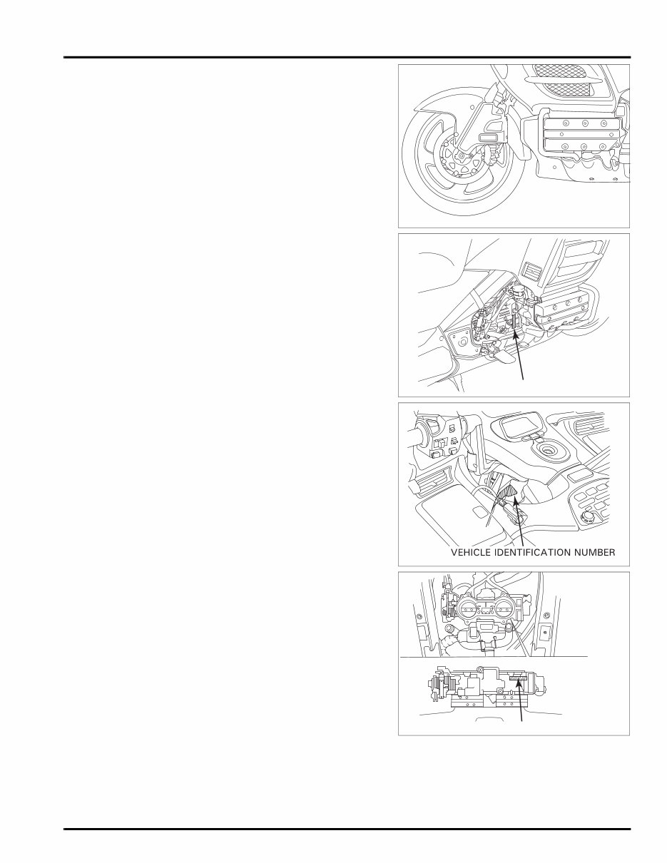
The frame serial number is stamped on the right side of the steering
head.
The engine serial number is stamped on the right side of the
crankcase.
The Vehicle Identification Number (VIN) is located on the left side of
the frame near the steering head.
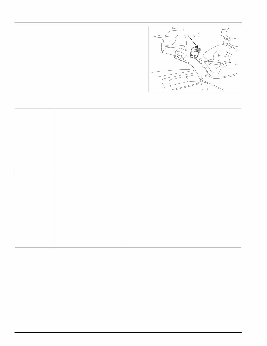
The throttle body identification number is stamped on the rear of the
throttle body.
ENGINE SERIAL NUMBER
THROTTLE BODY IDENTIFICATION NUMBER
GENERAL INFORMATION
1-4
The color label is attached on the back of the fuel fill compartment lid.
When ordering color-coded parts, always specify the designated color
code.
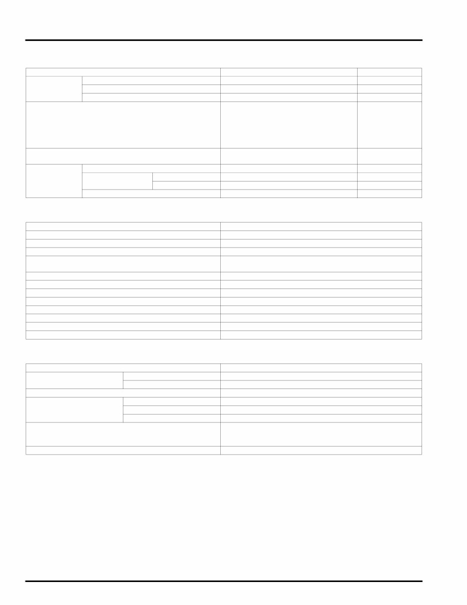
GENERAL SPECIFICATIONS
COLOR LABEL
ITEM SPECIFICATIONS
DIMENSIONS Overall length 2,635 mm (103.7 in)
Overall width 945 mm (37.2 in)
Overall height 1,455 mm (57.3 in)
Wheelbase 1,690 mm (66.5 in)
Seat height 740 mm (29.1 in)
Footpeg height 251 mm (9.9 in)
Ground clearance 125 mm (4.9 in)
Dry weight No ABS: 359 kg (791 lbs)
ABS model: 362 kg (798 lbs)
Curb weight No ABS: 399 kg (880 lbs)
ABS model: 402 kg (886 lbs)
Maximum weight capacity U.S.A type: 189 kg (417 lbs)
Canada type: 193 kg (425 lbs)
FRAME Frame type Diamond
Front suspension Telescopic fork
Front axle travel 122 mm (4.8 in)
Rear suspension Swingarm
Rear axle travel 105 mm (4.1 in)
Front tire size 130/70R18M/C 63H
Rear tire size 180/60R16M/C 74H
Front tire brand D250F (Dunlop), G709 RADIAL (Bridgestone)
Rear tire brand D250 (Dunlop), G704 RADIAL (Bridgestone)
Brake system Linked Brake System (LBS: All models) with
Anti-lock Brake System (ABS: GL1800A)
Front brake Hydraulic double disc
Rear brake Hydraulic single disc
Caster angle 29° 15’
Trail length 109 mm (4.3 in)
Fuel tank capacity 25 liters (6.6 US gal, 5.5 Imp gal)
GENERAL INFORMATION
1-5
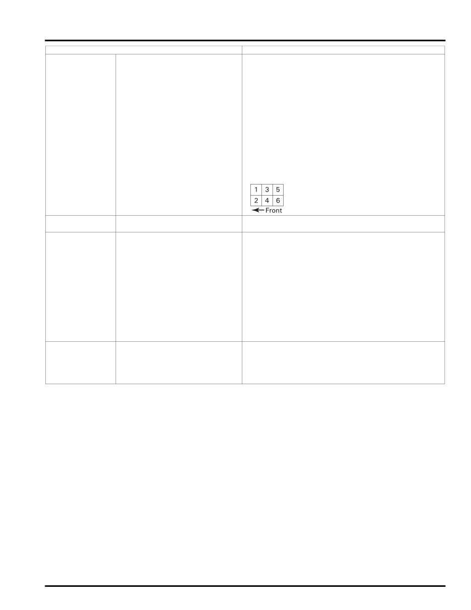
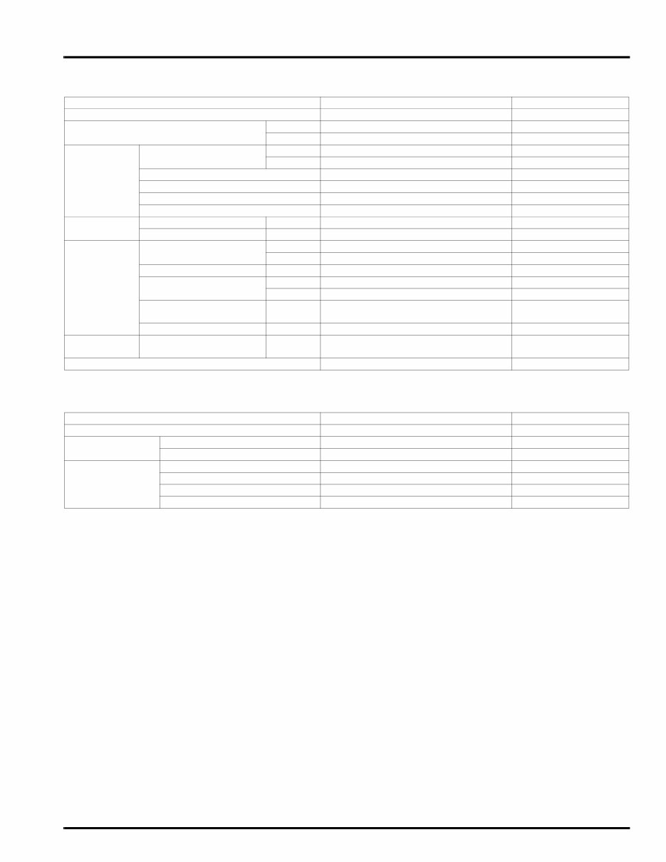
ENGINE Cylinder arrangement Flat six
Bore and stroke 74.0 x 71.0 mm (2.91 x 2.80 in)
Displacement 1,832 cm
3
(111.8 cu-in)
Compression ratio 9.8 : 1
Valve train Silent cam chain driven, OHC
Intake valve opens –5° BTDC (5° ATDC) (at 1 mm lift)
closes 30° ABDC (at 1 mm lift)
Exhaust valve opens 30° BBDC (at 1 mm lift)
closes –5° ATDC (5° BTDC) (at 1 mm lift)
Lubrication system Forced pressure and wet sump
Oil pump type Trochoid
Cooling system Liquid cooled
Air filtration Viscous paper element
Engine dry weight 118.3 kg (260.8 lbs)
Firing order 1 – 4 – 5 – 2 – 3 – 6
Cylinder number
FUEL DELIVERY
SYSTEM
Type Programmed Fuel Injection (PGM-FI)
Throttle bore 40 mm (1.6 in)
DRIVE TRAIN Clutch system Multi-plate, wet (hydraulically assisted)
Clutch operation system Hydraulically operated
Transmission Constant mesh, 5-speeds with reverse
Primary reduction 1.591 (78/49)
Secondary reduction (output
drive)
1.028 (36/35)
Final reduction 2.750 (33/12)
Gear ratio 1st 2.375 (38/16)
2nd 1.454 (32/22)
3rd 1.068 (31/29)
4th 0.843 (27/32)
5th 0.686 (24/35)
Gearshift pattern Left foot operated return system, 1 – N – 2 – 3 – 4 – 5
ELECTRICAL Ignition system Full transistorized ignition
Starting system Electric starter motor
Charging system Triple phase output alternator
Regulator/rectifier Triple phase full-wave rectification with field coil
Lighting system Battery
ITEM SPECIFICATIONS
GENERAL INFORMATION
1-6
LUBRICATION SYSTEM SPECIFICATIONS
Unit: mm (in)
FUEL SYSTEM (Programmed Fuel Injection) SPECIFICATIONS
COOLING SYSTEM SPECIFICATIONS
ITEM STANDARD SERVICE LIMIT
Engine oil
capacity
After draining 3.6 liters (3.8 US qt, 3.2 Imp qt) –
After draining/filter change 3.7 liters (3.9 US qt, 3.3 Imp qt) –
After disassembly 4.6 liters (4.9 US qt, 4.0 Imp qt) –
Recommended engine oil Pro Honda GN4 or HP4 (without
molybdenum additives) 4-stroke oil
or equivalent motor oil
API service classification SG or Higher
JASO T 903 standard: MA
Viscosity: SAE 10W-40
–
Oil pressure (at oil pressure switch) 530 kPa (5.4 kgf/cm
2
, 77 psi) at
5,000 rpm/80° C (176° F)
–
Oil pump Tip clearance 0.15 (0.006) 0.20 (0.008)
Body clearance Feed side 0.15 – 0.21 (0.006 – 0.008) 0.35 (0.014)
Scavenge side 0.15 – 0.22 (0.006 – 0.009) 0.35 (0.014)
Side clearance 0.02 – 0.09 (0.001 – 0.004) 0.12 (0.005)
ITEM SPECIFICATIONS
Throttle body identification number GQ61A
Throttle grip free play 2 – 6 mm (1/12 – 1/4)
Intake air temperature sensor resistance (20° C/68° F) 2.2 – 2.7 kΩ
Engine coolant temperature sensor resistance
(20° C/68° F)
2.3 – 2.6 kΩ
Throttle sensor resistance (20° C/68° F) 4 – 6 kΩ
Fuel injector resistance (20° C/68° F) 11.1 – 12.3 Ω
Camshaft position sensor peak voltage 0.7 V minimum
Ignition pulse generator peak voltage 0.7 V minimum
Manifold absolute pressure at idle 400 – 450 mm Hg (15.7 – 17.7 in Hg)
Fuel pressure at idle 343 kPa (3.5 kgf/cm
2
, 50 psi)
Fuel pump flow (at 12 V) 133 cm
3
(4.5 US oz, 4.7 Imp oz) minimum/10 seconds
Idle speed 700 ± 70 rpm
ITEM SPECIFICATIONS
Coolant capacity Radiator and engine 3.53 liters (3.73 US qt, 3.11 Imp qt)
Reserve tank 0.65 liter (0.69 US qt, 0.57 Imp qt)
Radiator cap relief pressure 108 – 137 kPa (1.1 – 1.4 kgf/cm
2
, 16 – 20 psi)
Thermostat Begin to open 76 – 80° C (169 – 176° F)
Fully open 90° C (194° F)
Valve lift 8 mm (0.3 in) minimum
Recommended antifreeze Pro Honda HP Coolant or an equivalent high quality
ethylene glycol antifreeze containing silicate-free
corrosion inhibitors
Standard coolant concentration 1:1 mixture with recommended antifreeze and soft water
GENERAL INFORMATION
1-7
CYLINDER HEAD/VALVE SPECIFICATIONS
Unit: mm (in)
CLUTCH SPECIFICATIONS
Unit: mm (in)
ITEM STANDARD SERVICE LIMIT
Cylinder compression at 300 rpm 1,383 kPa (14.1 kgf/cm
2
, 201 psi) –
Valve clearance IN 0.15 (0.006) –
EX 0.22 (0.009) –
Camshaft Cam lobe height IN 41.610 – 41.690 (1.6382 – 1.6413) 41.58 (1.637)
EX 41.680 – 41.760 (1.6409 – 1.6441) 41.65 (1.640)
Runout – 0.03 (0.001)
Journal O.D. 27.959 – 27.980 (1.1007 – 1.1016) 27.96 (1.101)
Journal I.D. 28.000 – 28.021 (1.1024 – 1.1032) 28.05 (1.104)
Oil clearance 0.020 – 0.062 (0.0008 – 0.0024) 0.10 (0.004)
Valve lifter Valve lifter O.D. IN/EX 28.978 – 28.993 (1.1409 – 1.1415) 28.97 (1.141)
Valve lifter bore I.D. IN/EX 29.010 – 29.026 (1.1421 – 1.1428) 29.04 (1.143)
Valve,
valve guide
Valve stem O.D. IN 4.970 – 4.995 (0.1957 – 0.1967) 4.96 (0.195)
EX 4.955 – 4.980 (0.1951 – 0.1961) 4.95 (0.195)
Valve guide I.D. IN/EX 5.000 – 5.012 (0.1969 – 0.1973) 5.04 (0.198)
Stem-to-guide
clearance
IN 0.005 – 0.042 (0.0002 – 0.0017) 0.075 (0.0030)
EX 0.020 – 0.057 (0.0008 – 0.0022) 0.085 (0.0033)
Valve guide projection
above cylinder head
IN/EX 11.8 – 12.0 (0.46 – 0.47) –
Valve seat width IN/EX 0.9 – 1.1 (0.035 – 0.043) 1.5 (0.06)
Valve
spring
Free length IN/EX 38.20 (1.504) 37.0 (1.46)
Cylinder head warpage – 0.10 (0.004)
ITEM STANDARD SERVICE LIMIT
Specified clutch fluid DOT 4 brake fluid –
Clutch master
cylinder
Cylinder I.D. 14.000 – 14.043 (0.5512 – 0.5529) 14.055 (0.5533)
Piston O.D. 13.957 – 13.984 (0.5495 – 0.5506) 13.945 (0.5490)
Clutch Clutch spring free height 4.8 (0.19) 4.6 (0.18)
Clutch lifter spring free height 2.9 (0.11) 2.5 (0.10)
Disc thickness 3.72 – 3.88 (0.146 – 0.153) 3.5 (0.14)
Plate warpage – 0.30 (0.012)
GENERAL INFORMATION
1-8
GEARSHIFT LINKAGE/TRANSMISSION SPECIFICATIONS
Unit: mm (in)
CYLINDER/PISTON/CRANKSHAFT SPECIFICATIONS
Unit: mm (in)
ITEM STANDARD SERVICE LIMIT
Output shaft Damper spring free length 66.0 (2.60) 64.0 (2.52)
Shaft O.D. 22.008 – 22.021 (0.8665 – 0.8670) 21.99 (0.866)
Gear bushing I.D. 22.026 – 22.041 (0.8672 – 0.8678) 22.05 (0.868)
O.D. 25.959 – 25.980 (1.0220 – 1.0228) 25.95 (1.022)
Driven gear I.D. 26.000 – 26.013 (1.0236 – 1.0241) 26.03 (1.025)
Shift fork I.D. 14.000 – 14.018 (0.5512 – 0.5519) 14.04 (0.553)
Claw thickness 5.93 – 6.00 (0.233 – 0.236) 5.6 (0.22)
Shift fork shaft O.D. 13.966 – 13.984 (0.5498 – 0.5506) 13.90 (0.547)
Transmission Gear I.D. M4 31.000 – 31.025 (1.2205 – 1.2215) 31.04 (1.222)
M5 35.000 – 35.025 (1.3780 – 1.3789) 35.04 (1.380)
C2, C3 33.000 – 33.025 (1.2992 – 1.3002) 33.04 (1.301)
Gear bushing O.D. M4 30.950 – 30.975 (1.2186 – 1.2195) 30.93 (1.218)
M5 34.950 – 34.975 (1.3760 – 1.3770) 34.93 (1.375)
C2, C3 32.950 – 32.975 (1.2972 – 1.2982) 32.93 (1.296)
Gear-to-bushing clearance 0.025 – 0.075 (0.0010 – 0.0030) 0.10 (0.004)
Gear bushing I.D. M4 28.007 – 28.028 (1.1026 – 1.1035) 28.04 (1.104)
M5 32.007 – 32.028 (1.2601 – 1.2609) 32.04 (1.261)
Mainshaft O.D. at M4 27.987 – 28.000 (1.1018 – 1.1024) 27.96 (1.101)
at M5 31.987 – 32.000 (1.2593 – 1.2598) 31.96 (1.258)
Bushing-to-shaft clearance 0.007 – 0.041 (0.0003 – 0.0016) 0.08 (0.003)
ITEM STANDARD SERVICE LIMIT
Cylinder I.D. 74.000 – 74.015 (2.9134 – 2.9140) 74.10 (2.917)
Out-of-round – 0.10 (0.004)
Taper – 0.10 (0.004)
Warpage – 0.05 (0.002)
Piston,
piston pin,
piston ring
Piston O.D. at 10 mm (0.4 in) from
bottom
73.970 – 73.990 (2.9122 – 2.9130) 73.85 (2.907)
Piston pin hole I.D. 18.010 – 18.016 (0.7091 – 0.7093) 18.03 (0.710)
Piston pin O.D. 17.994 – 18.000 (0.7084 – 0.7087) 17.99 (0.708)
Piston-to-piston pin clearance 0.010 – 0.022 (0.0004 – 0.0009) 0.05 (0.002)
Piston ring end
gap
Top 0.15 – 0.30 (0.006 – 0.012) 0.5 (0.02)
Second 0.30 – 0.45 (0.012 – 0.018) 0.6 (0.02)
Oil (side
rail)
0.20 – 0.70 (0.008 – 0.028) 0.9 (0.04)
Piston ring-to-ring
groove clearance
Top 0.025 – 0.055 (0.0010 – 0.0022) 0.10 (0.004)
Second 0.015 – 0.045 (0.0006 – 0.0018) 0.10 (0.004)
Cylinder-to-piston clearance 0.010 – 0.045 (0.0004 – 0.0018) 0.10 (0.004)
Crankshaft Connecting rod side clearance 0.15 – 0.30 (0.006 – 0.012) 0.40 (0.016)
Crankpin bearing oil clearance 0.028 – 0.046 (0.0011 – 0.0018) 0.06 (0.002)
Main journal bear-
ing oil clearance
1, 4 0.012 – 0.030 (0.0005 – 0.0012) 0.06 (0.002)
2, 3 0.020 – 0.038 (0.0008 – 0.0015) 0.06 (0.002)
Runout – 0.03 (0.001)
Crankpin and
main journal
Taper – 0.003 (0.0001)
Out-of-
round
– 0.005 (0.0002)
You're Reading a Preview
What's Included?
Fast Download Speeds
Online & Offline Access
Access PDF Contents & Bookmarks
Full Search Facility
Print one or all pages of your manual
$31.99
Viewed 83 Times Today


Secure transaction
What's Included?
Fast Download Speeds
Online & Offline Access
Access PDF Contents & Bookmarks
Full Search Facility
Print one or all pages of your manual
$31.99
This complete 2001-2010 Honda Gold Wing GL1800/GL1800A OEM Service & Repair Manual is available for instant access on your computer, tablet, or smartphone.
- Access comprehensive factory service repair information tailored for the 2001-2010 Honda Gold Wing GL1800/GL1800A models.
- Benefit from detailed repairs, servicing, and troubleshooting procedures demonstrated with step-by-step instructions, detailed photos, and clear exploded diagrams that meet the high standards required by professional mechanics and DIY enthusiasts alike.
- Navigate through each repair task with precise, easy-to-follow guidance supported by highly detailed exploded views and illustrative pictures.
- Enjoy the flexibility to print single pages or the entire manual to suit your work environment.
- This is the complete OEM manual without any limitations or trial periods, offering lifetime access without renewal or additional fees.
- It is fully compatible with all Windows and MAC computers.
Thanks for considering this manual. Click the button to access it.


