HOW TO USE THIS MANUAL This servloe mallUaJ de&cribes tile service procedures /of the CRFSOF Follow the Malntenal"lOe Schltdule (Sedion 3) recommendaltoos 10 ens.url:l ilia! the \/elide illn peale. operat;,.g conditton and !he em<$$IOn I8wIs are vmhin !he aIaodard set by !he U 5 EO'M.omental PrOlec1ioro Age«;y (EPA) and Cel!lomia Air Resources Board (CARB) F'Irrfoomng the Hnil scheduled maIntenance 1$ .-.ry Importanl " comp&nS8tes lor the n.r..1 wear thaI occurs dumg the break·," penod 5ections \ and 3 apply to the wnole motorcycle SectIOn 2 Illustrates proced!Jres for removaV",staliabon 01 components thaI may be reqUired to perXlm1 selVice duct,b&d in the 1oI1ow'f1g $&Cllon" Section 4 through 14 describe parIs 01 the moIorcyde. grouped according to Mx:a1iOfl rod !he secbOO you waN on tIu$ page. men tum to the table 01 conlants on the Ii<$I page 01 the MCIion MosI sactlOllS SIan wUh an assembly 01 ')'SIlIm iIIusIr.l1ion. servICe informabOrl and IroobIes/looI,ng /0. !he S8d!OO The subseqlll!nt pages give detailed procedVre$ II you dOO~ know !he 1IoOU1C8 01 tile trouble , go to SecIIOO 16 TroubIeshoo!lfIg 'I'our safety, and the salllly 01 0Ch&rs. if, YefY Oriportant To help )'OU makil inb"med 08eiI!0nI we have pfOYlded safety messages and oth&r inlormallon truOl,<ghou! tho. mat\tlfll 01 course, ~ 1$ not 1)f8ctlC81 Of possible to warn you a.bout all tile hazards IISSOC1ated wolh servleir.g mus vehicle You must use your own good judgemafll You writ lind impo<tanl safety inlorrnallOO in • variety of Iorms inclUding • Safllrv LaDe" - on the vetude • Safety Massages - preceded by • saJely alert symbol .l.. and one at Ihree signal words, OAJlfGEA. WARNING_ Of CAUTION These sqlal wotOs mean You WILL be KILLED Of SERIOUSLY rgt"'ntli;' HURT ~ you don'lloIkM- InSlrUCIKlrIS You CAN be KILLED or SERIOUSLY HURT m ' bn W "fit! II you don', tallow InslrUcttons_ You CAN be HURT ~ you don't IoIIow "ew'''lIlf' onSlrudJOn$ • InstrUCIIOOS - how 10 .servICe mill YeI10CIe OOITectty end salary As you read this manl,llll, you wllll , 1l(! in!o<mll!'On thai IS preceded by /I NOnCrl symbol . The purpose 01 lhls message is to help prevent damage to YOUl \/Ilhocte. O1I1er Pfoperty, or ttle envuonmenl ;:; '" a: .... w ~ a: c c z '" w z ;; z w CONTENTS GENERAL INFORMATION MAINTENANCE LUBRICATION SYSTEM FUEL SYSTEM ENGINE REMOVAUINSTAllATION CYLINDER HEADNALVES CYLINDER/PISTON CLUTCH/GEARSHIFT LINKAGE ALTERNATOAICAM CHAIN TENS lON ER CRANKSHAFTITRANSMISSIOWKICKSTARTER REAR WHEEUBRAKEISUSPENSION IGNITION SYSTEM WIRING DIAGRAM TROUBLESHOOTING INDEX
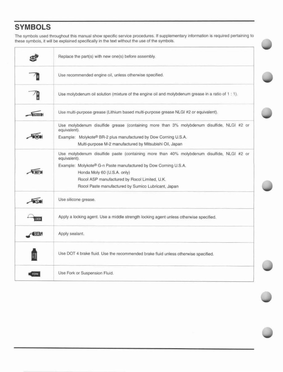
SYMBOLS The symbols used throughout this manual show specific service procedures. II supplementary information is required pertaining to these symbols, It will be explained specifically In the text without the use of the symbolS. g Replace the part(s) with new ooa(s) before assembly. "78 Use recommended engIne oil, unless otherwise specified. - , 78 Use molybdenum 011 solulioo (mixture 01 the engine 011 and molybdenum grease in a ratio of 1 : 1), I s;;;.. Use multi-purpose grease (lithium based multi-purpose grease NLGI #12 or equivalent). - Use molybdenum disulfide grease (containing more than 3% molybdenum disulfide, NLGI #2 or equivalent), .... Example: MoIykoteil BA-2 plus manufactured by Dow Corning U.S.A. Multi·purpose M-2 manufactured by Mitsubishi Oil, Japan -- - Use molybdenum disulfide paste (containing more than 40% molybdenum dIsulfide, NLGI #2 or equivalent). Example: MolykoteQII G-n Paste manufactured by Dow Corning U.S.A. ~ Honda Moly 60 (U.S.A. only) Rocol ASP manufactured by Rocol Limited, U.K. Rocol Paste manufactured by Sumlco Lubricant, Japan - - ...-'iiSIII Use silicone grease. a. u Apply a locking agent. Use a middle strength locking agent unless otherwise specified. ,J"1l!1Il Apply sealant I Use DOT 4 brake lIuid. Use the recommended brake ftuid unless otherwise specified . .. Use Fork or Suspension Fluid.
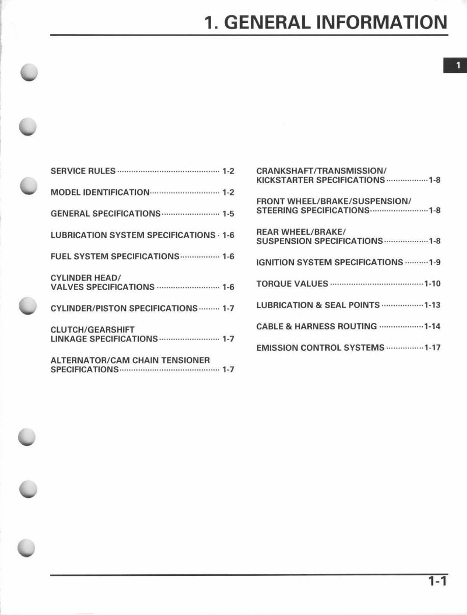
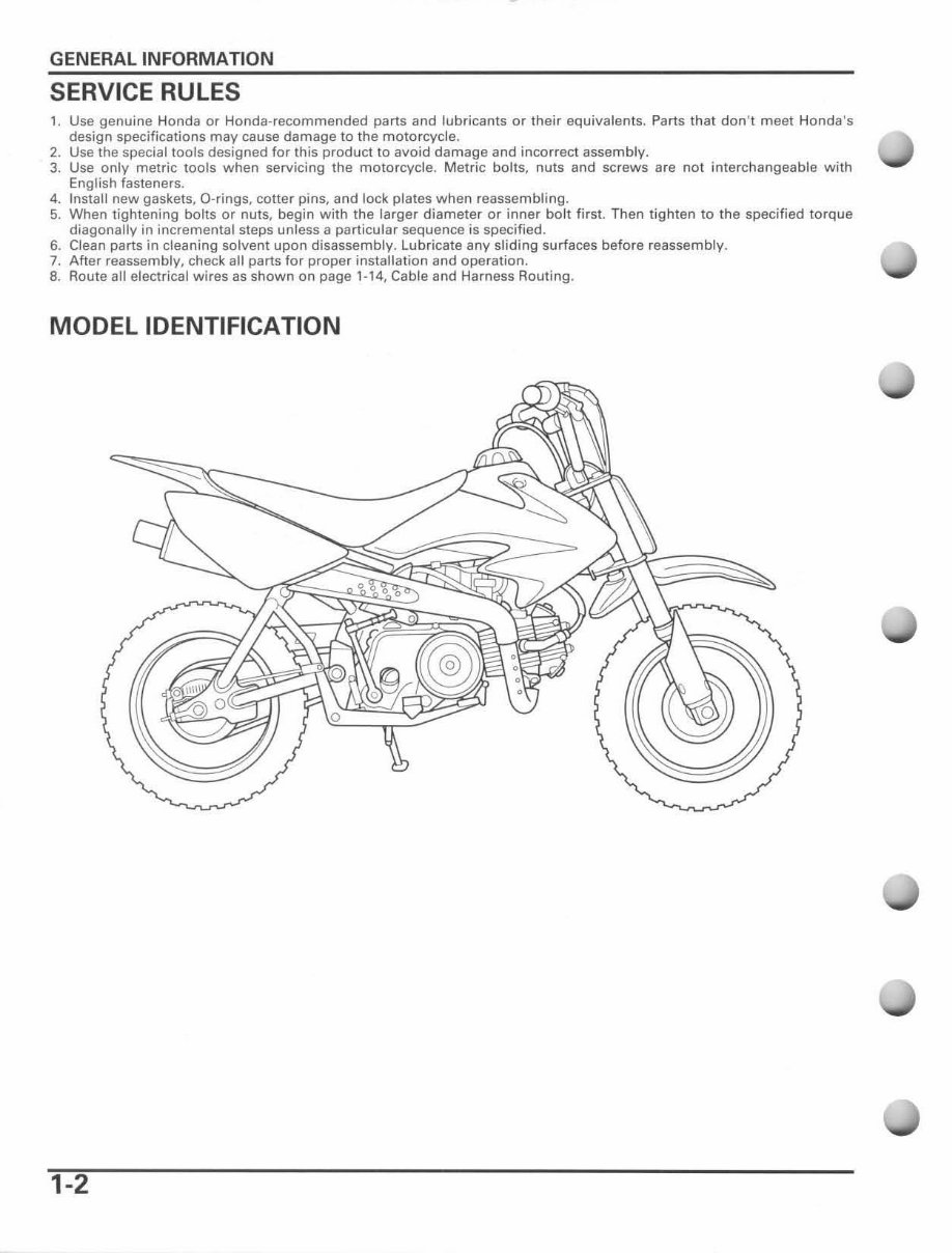
GENERAL INFORMATION SERVICE RULES 1. Use genuine Honda or Honda-recommended parts and lubricants or the ir equivalents . Parts that don 't meet Honda's design specifications may cause damage to the motorcycle. 2. Use the special tools designed for this product to avoid damage and incorrect assembly. 3. Use only metric tools when servicing the motorcycle. Metric bolts, nuts and screws are nol interchangeable with English fasteners. 4. Install new gaskets, O-rings. cotter pins, and lock plates when reassembling. 5. When tightening bolts or nuts, begin with the larger diameter or i nner bolt first. Then tighten to the spec if ied torque diagonally in incremental steps unless a particular sequence is specified. 6. Clean parts in cleaning solvent upon disassembly. Lubricate any sl iding surfaces before reassembly. 7. After reassembly, check all parts for proper installation and operation. 8. Route all electrical wires as shown on page 1-14, Cable and Harness Routing . MODEL IDENTIFICATION 1-2
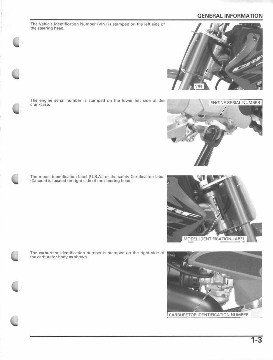
, The Vehicle Identification Number (VIN) is stamped on the left side of the steering head. The engine serial number is stamped on the lower left side of the crankcase. The model identification label (U.S.A.) or th e safety Certification label (Canada) is located on right side of the steering head. The carburetor identification number is stamped on the right side of the carburetor body as shown . GENERAL INFORMATION 1-3
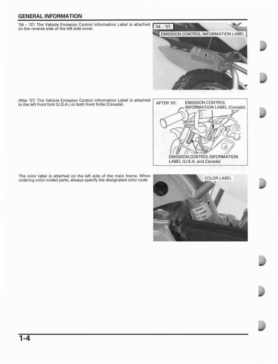
GENERAL INFORMATION ' 04 - '07: The Vehicle Emission Conlrol Information label is attached on the reverse side of the left side cover. After ' 07 : The Vehicle Emission Control Information label is attach ad ,----------,------- - - to the leh fro nl fork (U.S.A.) or both front forks (Canada). AFTER ' 07 : EM ISSION CONTROL INFORMATION LABEL (Canada) EM ISSION CONTROL INFORMATION LABElIU.5A and Canada) The color label is allached on the left side of the main frame. When P--- .... .., ....... , ordering color.-coded parts, always specify the deslgnaled color code. 1-4
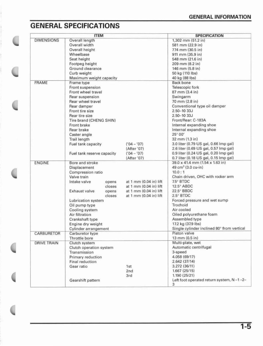
GENERAL SPECIFICATIONS I I Overall width Overall height Wheelbase Sea t height Foolpeg height Ground clearance Curb weight Front suspension Front wheel travel Rear suspension Rear wheel tr avel Rear damper Front tire size Rear tire size Tire brand (CHENG SHIN) Front brake Rear brake Casler angle Trail length Fuel lank capacity Fuel tank reserve capacity Displacement Compression ratio Valve train Intake valve opens closes Exhaust valve opens Lubrication system Oil pump type Cooling system Air filtration Crankshaft type dry weight system doses Clutch operation system Transmission Primary reduction Final reduction Gear ratio Gearshift panern (' 04- '07) (After ' 07) ('04 - '07) al 1 mm (0.04 in) tift at 1 mm (0.04 in) lift at , mm (0 .04 iollift at 1 mm (0 .04 in) Jift ,,, 2nd 3,d GENERAL INFORMATION mm 58 1 mm (22.9 in) 774 mm (30.5 in) 911 mm (35.9 in) 548 mm (21.6 in) 209 mm (8.2 in) 146 mm (5.8 in) 50 kg (110 Ibs) Telescopic fork 87 mm (3.4 in) Swingarm 70 mm (2.8 in) Conventional type oil damper 2.50-1033J 2.50-1033J Front/Rear: C·183A Internal expanding shoe Internal expanding shoe 25° 00' 32 mm (1.3 in) 3.0 liter (0.79 US gal, 0.66 Imp gal) 2.61i1er (0.69 US gal, 0.57 Imp gal) 0.9 liter (0.24 US gal, 0.20 Imp gal) 0.7 . t8US 0.15 I 49 cm' (3.0 cu·in) 10.0 : 1 Chain driven, OHC with roctet arm 7.5 0 BTDC 12.5° ABDC 22 .5° BBDC 2,so BTDC Forced pressure and wet sump Trochoid Air cooled Oiled polyurethane foam Assembled type , 7.2 kg (37.9 Ibs) inclined 80° Automatic centrifugal 3·speed 4.058 (69117) 2.642137/ '4) 3.272136111) 1.667 (25115) 1.190 (25121) Left foot operated return system, N - 1- 2- 1-5
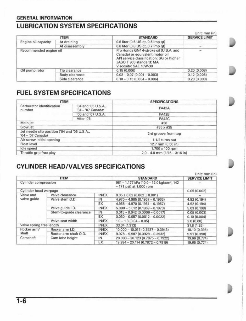
GENERAL INFORMATION LUBRICATION SYSTEM SPECIFICATIONS Canada) or equivalent mOler oil API service classification: SG or higher JASOT . MA FUEL SYSTEM SPECIFICATIONS number PA42A 2rd groove from top CYLINDER HEADIVALVES SPECIFICATIONS valve guide I I 1-6 I I
The 2004-2015 Honda CRF50F Service & Repair Manual is the factory-authorized guide to maintaining and repairing Honda’s long-standing mini dirt bike. Covering all model years from 2004 through 2015, this manual includes precise specifications, service instructions, and full rebuild procedures for the CRF50F’s 49cc engine, drivetrain, suspension, brakes, and electrical systems.
Whether you're a seasoned mechanic or a dedicated mini-moto enthusiast, this manual provides everything needed to handle both routine maintenance and major overhauls. It includes detailed diagrams, torque specifications, safety inspections, and a complete maintenance schedule based on model year. All wiring schematics and component layouts are provided to ensure accuracy during repairs.
Content Overview:
General Information: Model identification, VIN location, maintenance intervals
Engine: Cylinder head service, piston removal, cam chain, crankshaft, and transmission