

2004-2009 CRF250R Service & Repair Manual
What's Included?
Fast Download Speeds
Online & Offline Access
Access PDF Contents & Bookmarks
Full Search Facility
Print one or all pages of your manual
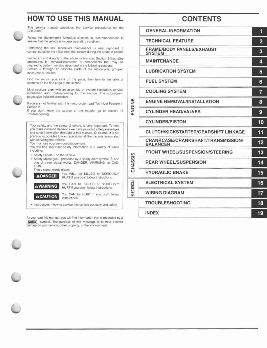
HOW TO USE THIS MANUAL
n.. 5eI'VII)8 manual descobM It1e servICe procedures lot the
CAF250A.
Follow the MaIntenance SChedule (Sectlon 4) recommendabOOs to
ensure thallhe veh,.;le is. 10 peak operating condition.
Pel1o<ming the first SCheduled mallltenance ~ very ,mpottanl II
compensates lor \he IIVMI wearlhilt occurs dunng!he break..n penod.
SeehG'" 1 and 4 apPly 10 the whole moIOI'cycIe SectiorI 3 ilktstrates
procedures lor remova1ronstallatlOl'1 01 components that may be
reqUired 10 perform IOervOCEl described in !he IoIloWII'Ig secilO!lS.
SectIOn 5 thfough 11 descnbe parts 01 lIle molort:yde. grouped
~,ng 10 IocabOl'l,
~~ the secllOI1 you walll on IIlI$ page, then tum 10 !he table 01
contents on the "<51 page 01 Ihe &eCbOn
Most sections star! Wllh an assembly or 5ystam l«uS!l'Ilhon, service
lnformatiOf1 and IrOUbleshoobng lor the sectlOt'l The subsequent
pages ~ oetadecl procedure
" you are not lam ilia, WIth IIlIS ITIQIOrcycle read TectlrllcaJ Feature In
5&Cllo02.
II you don' know the source 01 Iha trooble, QO to secttOn 18
TlOUbIeshootlng
Your safety. and the safety 01 others. is very important To tl&lp
you mai<6 informed deciSIonS we have provided safety massages
and other ,nlormaTion throughout Ihls manual. 01 course. II is not
practICal or ~ to warn you about all the hazards a!iSOCl8.!ed
WJItlsemclng Ihls vehICle
You mum use your 0WTl good liJdger'l1el1l
You witl find Impoftant safety r1lormatl(lO'1 !f1 a O/8r1ety of /ofnu
lnduding;
• S8fety Labotls - 01'1 the whde
• S8fety Messages - preceded II)' a safety alert symbol i and
one of three 191al W!lfd$. OANGER WARNtNG. Of CAU-
noo
These SIgflal words mean
You WILL be KILLED or SERIOUSLY
rg'l+}\in,j' HURT If you doll'! follow instructIOns
You CAN be KILlED or SERIOUSlY
m 'Lh~ i!f' 1tIt! HURT ~ you doll·, IoIIow InllJ\ICIJOnS
You CAN 00 HURT I. you don·t ~Iow
M'W"fl'li' Instructions
• InstrucbOOll - I"IO'N 10 &efVIC8 Itus vehicle COfractty and safety.
AS)'OI,I read this manu.al. )'01,1 will 'Ind infollnation that IS preceded by a
..HOTiCEl symbol The purpose of th.s message Is to help pf_nt
damage to your vehICle. oCher prOptrty or the elMf'Ol"omanl.
w
z
a
z
w
III
iii
III
..
J:
l)
CONTENTS
GENERAL INFORMATION
TECHNICAL FEATURE
MAINTENANCE
LUBRICATION SYSTEM
FUEL SYSTEM
COOLING SYSTEM
ENGINE REMOVALJlNSTALLATION
CYLINDER HEAONALVES
CYLINOERIPISTON
REAR WHEELJSUSPENSION
HYORAULIC BRAKE
ELECTRICAL SYSTEM
WIRING DIAGRAM
TROUBLESHOOTING
INDEX
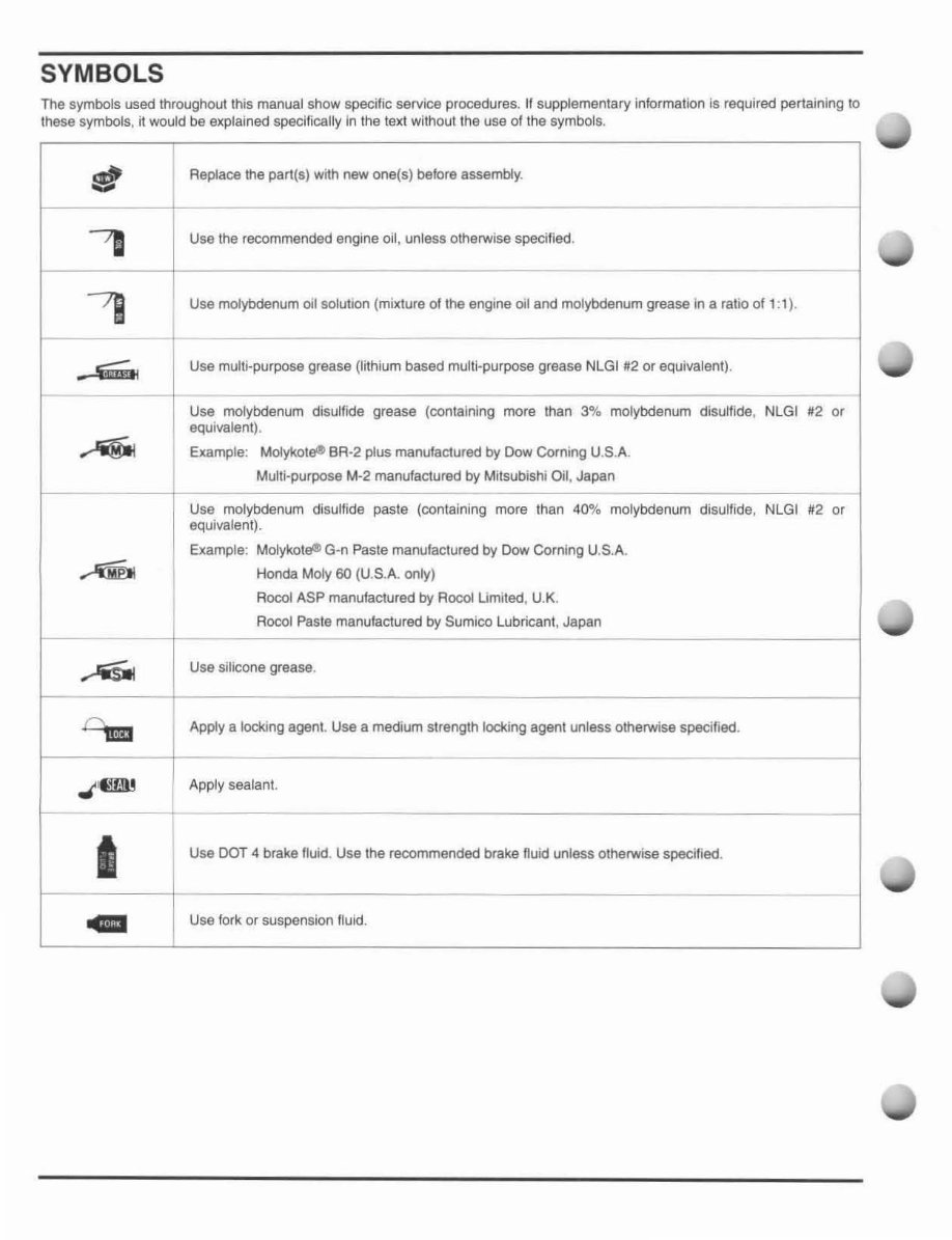
SYMBOLS
The symbols used throughout this manual show specific service procedures. If supplementary information Is required pertaining to
these symbols, it would be explained specifically In the text wilhoul l he use of the symbols.
:11
I Replace the part(s) with new one(s) before assembly.
'B
Usa the recommended engine oil, unless otherwise specified .
7J
Use molybdenum oil solution (mixture of the engine oil and molybdenum grease in a ratio of 1: 1).
• .s;;:;;..
Use multi-purpose grease (lithium based mUlti-purpose grease NLGI #2 or equivalent).
Use molybdenum disulfide grease (containing more than 3% molybdenum disulfide, NlGI #2 or
equ ivalent) .
~
Example: MoIykot~ BR-2 plus manufactured by Dow Corning U.S.A.
Multi-purpose M-2 manufactured by Milsubishi Oil, Japan
Use molybdenum disulfide paste (containing more than 40% molybdenum disulfide, NLGI #2 or
equivalent).
Example: Molykot~G·n Paste manufactured by Dow Corning U.S.A.
~ Honda Moly 60 (U.S.A. only)
Rocol ASP manufactured by Rocol Limited, U.K.
Rocol Paste manufactured by Sumico Lubricant, Japan
.... -'iSioI
Use silicone grease.
Dum
Apply a locking agent. Use a medium strength locking agent unless othelWise specified .
.,( '@llll
Apply sealant.
-
I
Use DOT 4 brake fluid. Use the recommended brake nuid unless otherwise specified.
..
Use fork or suspension fluid .
1. GENERAL INFORMATION
SERVICE RULES ··················· .. · .. ···· ............ · 1-2
MODEL IDENTIFICATION····················· ··· ·· · 1-2
GENERAL SPECIFICATIONS······················ 1-4
LUBRICATION SYSTEM
SPECIFICATIONS ········································ 1-6
FUEL SYSTEM SPECIFICATIONS ·· ············ 1-6
COOLING SYSTEM SPECIFICATIONS ····· ·1-7
CYLINDER HEADIVALVES
SPECiFiCATIONS······································ ·· 1-7
CYLINDER/ PISTON SPECIFICATIONS ······ 1-8
CLUTCH/ KICKSTARTER/ GEARSHIFT
LINKAGE SPECIFICATIONS ·· ····· ·· ·········· ··· ·1-8
CRANKCASE/CRANKSHAFT /TRANSM IS-
SION/BALANCER SPECIFICATIONS ········· 1-9
FRONT WHEEL/SUSPENSION/STEERING
SPECIFICATIONS ······· ·· ··· ·· ················· ·· · .. ·1 -10
REAR WHEEL/SUSPENSION
SPECIFICATIONS ..................................... 1- 11
HYDRAULIC BRAKE SPECIFICATIONS··· 1-11
ELECTRICAL SYSTEM
SPECIFICATIONS ································ .. · .. 1-12
STANDARD TORQUE VALUES ··············· 1-13
ENGINE & FRAME TORQUE VALUES ·· ·· 1-13
LUBRICATION & SEAL POINTS·············· 1-19
CABLE & HARNESS ROUTING ............... 1-22
OPTIONAL PARTS ···································· 1-30
1-1
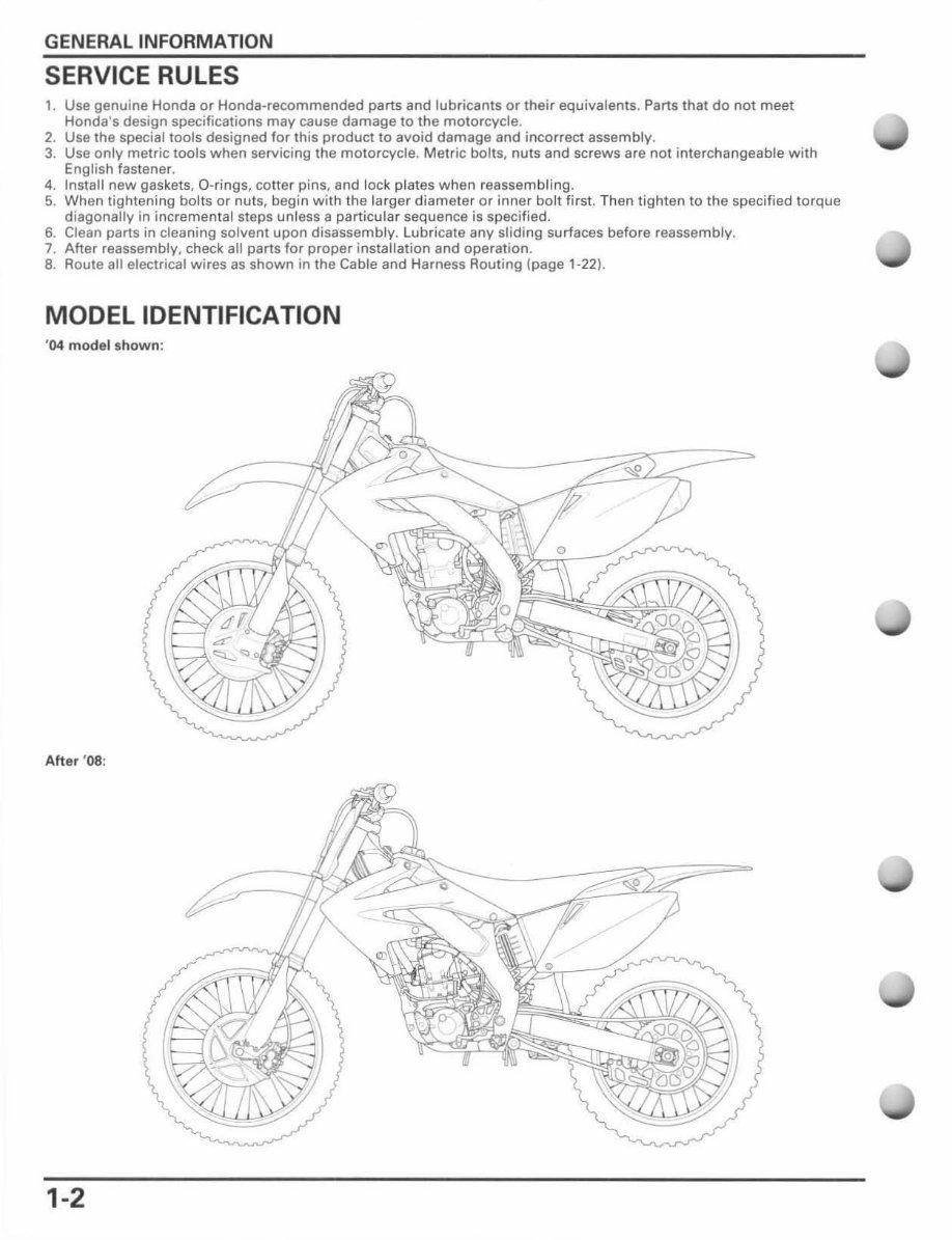
GENERAL INFORMATION
SERVICE RULES
1. Use genuine Honda or Honda -recommended parts and lubricants or their equivalents. Parts that do not meet
Honda's design specifications may cause damage to the moto rcycle.
2. Use the special tools designed for this product to avoid damage and incorrect assembl y.
3. Use only metric tools when servicing the motorcycle. Metric bolts, nuts and sc rews are not interchangeable with
English fastener.
4. Install new gaskets. O-rings, cotter pins, and lock plates when reassembling.
5. When tightening bolts or nuts, begin with the larger diameter or inner bolt first. Then tighten to the specified torque
diagonally in increment al steps unless a particular sequence is specified.
6. Clean parts in cleaning solvent upon disassembly. Lubricate any sliding surfaces before reassembly.
7. After reassembly, check all parts for proper installation and operation.
8. Route all electrical wires as shown in the Cable and Harness Routing (page 1-22).
MODEL IDENTIFICATION
' 04 mod el shown :
After ' 08 :
1-2
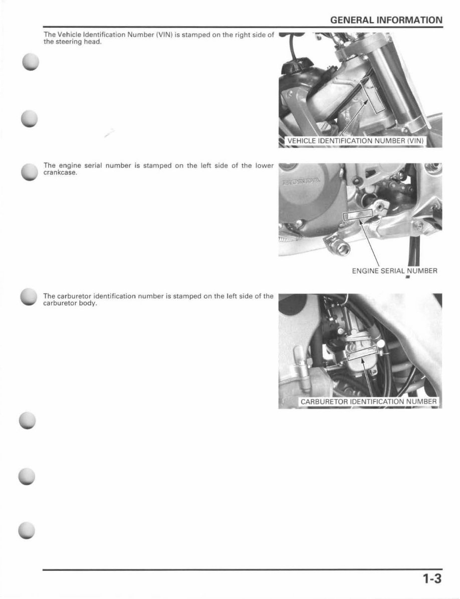
The Vehicle Identification Number (V1N ) is stamped on the right side of
the steering head.
The engine serial number is stamped on the left side of the lower
crankcase.
The ca r buretor identification number is stamped on the left side of the
carburetor body.
GENERAL INFORMATION
ENGINE SERIAL NUMBER
•
1-3
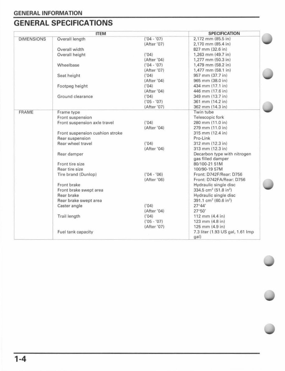
GENERAL INFORMATION
GENERAL SPECIFICATIONS
DIMENSIONS
FRAME
1-4
Overall length
Overall width
Overall height
Wheelbase
Seat height
F ootpeg height
Ground clearance
Frame type
Front suspension
ITEM
Front suspension axle travel
Front suspension cushion stroke
Rear suspension
Rear wheel travel
Rear damper
Fr ont tire size
Rear tire size
Tire brand (Dunlop)
Front brake
Front brake swept area
Rear brake
Rear brake swept area
Caster angle
Trail length
Fuel tank capacity
1'04 - '07)
(After '07)
1'04)
(After '04)
1'04 - '07)
(After '07)
1'04)
(After '04)
1'04)
(After '04)
1'04)
('05 - '07)
(After '07)
1'04)
tAtter '04)
1'04)
(Afte r '04)
1'04 - '06)
(After '06)
1'04)
(Afte r '04)
1'04)
1'05 - '07)
(After '07)
SPECIFICATION
2,172 mm (85.5 in)
2,170 mm (85.4 in)
827 mm (32.6 in)
1,263 mm (49.7 in)
1,277 mm (50.3 in)
1,479 mm (58.2 in)
1,477 mm (58. 1 in)
957 mm (37.7 in)
965 mm (38.0 in)
434 mm (17.1 in)
446 mm (17.6 in)
349 mm (13.7 in)
361 mm (14.2 in)
362 mm (14.3 in)
Twin tube
Telescopic fork
280 mm (11.0 in)
279 mm (11 .0 in)
315 mm ( 12.4 in)
Pro-link
312 mm (12.3 in)
313 mm (12.3 in)
Decarbon type with nitrogen
gas filled damper
80/1 00-21 51M
100 190-1957M
Front: 0742F/Rear: 0756
Front: 0742FAlRear: 0756
Hydraulic single disc
334.5 cm
l
(5 1.8 in
2
)
Hydraulic single disc
391. 1 cm? (60.6 in')
27°44'
27"50'
112 mm (4.4 in)
123 mm (4.8 in)
125 mm (4.9 in)
7.3 liter (1.93 US gal, 1.61 Imp
gal)
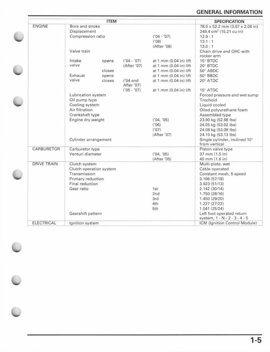
GENERAL INFORMATION
ITEM SPE CIFICATION
ENGINE Bore and stroke 78.0 x 52.2 mm (3.07 x 2.06 in)
Displacement 249.4 em
3
(15.2 1 cu-in)
Compression ratio ('04 - '07) 12.9 : 1
1'081 13.1 : 1
(Afte r '08) 13.0 : 1
Valve train Chain drive and OHC with
rocker arm
Intake opens r04 - '07) at 1 mm (0.04 in) lift 15" BTDC
valve (Afte r '07) at 1 mm (0.04 in) lift 20" BTDC
closes at 1 mm (0.04 in) lift 50" ABDC
Exhaust opens at , mm (0.04 in) lift 50" BBDC
valve
closes ('04 and at 1 mm (0.04 in) l ift 20" ATDC
After '07)
('05 - '07) at 1 mm (0.04 in) lift 15" ATDe
lubricati on system Forced pressure and wet sump
Oil pump type Trochoid
Cooling syst em Liquid cooled
Air filt r ation Oiled polyurethane foam
Crankshaft t ype Assemb led type
Engine dry weight (,04, '05) 23 . 90 kg (52 . 68 Ibsl
1'061 24.05 kg (53.02 Ibs)
1'071 24.08 kg (53.09 Ibs)
(After '07) 24.10 kg (53. 13Ibs)
j
Cylin der arrangement Single cy linder, inc l ined 10'
from vertical
CARBURETOR Carburetor type Pist on valve type
Venturi diameter 1'04, 'OS) 37 mm (1.5 in)
(Afte r '05) 40 mm (1.6 in)
DRIVE TRAIN Clutch system Multi -plate, wet
Clutch operation system Cable operated
Transmission Constant mesh, 5-speed
Primary reduct ion 3.166 (57/18)
Final reduction 3.923 (51113)
Gear ratio
,,,
2.142 (30/ 14 )
'o d
1.750 (28116)
3,d 1.450 (29/20)
4,h 1.227 (27122)
51h 1.041 (25124)
Gearshift pattern Left foot operated return
system, 1 - N - 2 - 3 - 4 - 5
ELE CTRI CAL Ignition system leM (Ign iti on Control Module )
1-5
GENERAL INFORMATION
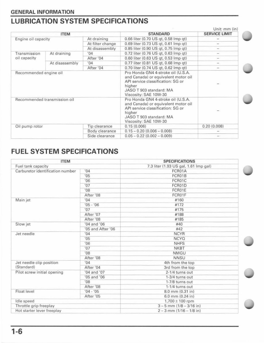
LUBRICATION SYSTEM SPECIFICATIONS
Engine oil capacity
oil capacity
AI i
and Canada) or equivalent molor oil
API service classification: SG or
higher
JASO T 903 standard: MA
Recommended transmission oil
____ ~,v~ ;s ~'~ O~S~ity;SAE'~OVV .~.3~°fecifnTSJC__1----------
Pro Honda GN4 4
Oil pump rotor
FUEL SYSTEM SPECIFICATIONS
IT EM
Fuel tank capacity
Carburetor identification number '04
h 05
ro 06
h a7
' 08
After 'OS
Main jet '04
j 5" 06
'07
After '07
After '08
Slow jet ' 04 and '06
: ' 05 and After '06
Jet needle '04
'05
' 06
' 07
r- '08
After '08
Jet needle dip position '04
(Standard) After '04
Pilot screw initial opening '04 and '07
r. 05 and '06
ro 08
~er'08
Fl oat level '04 - '05
After '05
,
Idle speed
Throttle grip freeplay
HOI starter lever freeplay
1-6
and Canada) or equivalent moto r oil
API service classification: SG or
higher
JASO T 903 standard: MA
Viscosity: SAE lOW-30
0. 15 (0.006)
SPECIFICATI ONS
7.3 liter (1.93 US gal. 1. Sl lmp gal)
FCR01A
FeROlB
FeAOle
FCR01D
FeR01E
FCR01F
"60
#172
:!:=
::~ -
NeYR
NeYQ
NH FS
NK8T
NMGU
NNSU
4th from the top
3rd from the top
2-1/4 turns out
1-314 turns out
1-7/8 turns out
' -' /4 turns out
8_0 mm (0.3 1 in)
6 .0 mm (0.24 in)
1,700 ± 100 rpm
3 5 mm ( 1/8 3/16 in)
2 3 mm (1116 1/8 in )
<
<
I
1
1
You're Reading a Preview
What's Included?
Fast Download Speeds
Online & Offline Access
Access PDF Contents & Bookmarks
Full Search Facility
Print one or all pages of your manual
$27.99
$36.99
Viewed 84 Times Today


Secure transaction
What's Included?
Fast Download Speeds
Online & Offline Access
Access PDF Contents & Bookmarks
Full Search Facility
Print one or all pages of your manual
$27.99
$36.99
This manual is a comprehensive guide for repairing the Honda CRF250R 2004-2009, featuring detailed illustrations and step-by-step instructions. It is designed for both DIY enthusiasts and professional mechanics, offering a cost-effective solution for maintaining your bike. The manual covers a wide range of topics including lubrication, maintenance, fuel system, engine removal/installation, and much more. Each manual provides in-depth, illustrated instructions for every service and repair procedure.
- Keyword Search
- General Information
- Lubrication
- Maintenance
- Fuel System
- Engine Removal / Installation
- Cylinder Head / Valves
- Cylinder / Piston
- Clutch / Gearshift Linkage
- Alternator / Cam
- Transmission
- Brake
- Suspension
- Ignition System
- Wiring Diagram
- Troubleshooting
- And Much More
File Format: PDF
Compatibility: All Versions of Windows & Mac
Language: English
Requirements: Adobe Reader
Instant Access
No Shipping Cost
No Need to Wait for a CD-ROM


