

•
•
•
•
•
•
•
•
•
•
.,
"
, .
..
How to use this manual
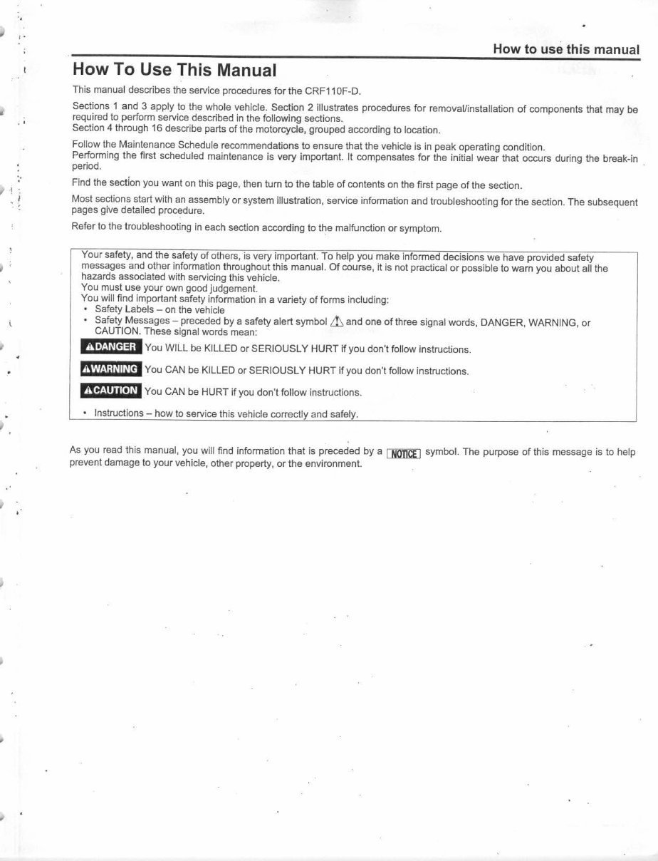
How To Use This Manual
This manual describes the service procedures for the CRF11 OF·D.
Sections 1 and 3 apply to the whole vehicle. Section 2 illustrates procedures for removallinstalialion of components that may be
required to perform service described in the following sections.
Section 4 through 16 describe parts of the motorcycle, grouped according to location.
Follow the Ma intenance Schedule recommendations to ensure that the vehicle is in peak operating condition.
Performing the first scheduled maintenance is very important. II compensates for the initial wear that occurs during the break-In
period. .
Find the sect ion you want on this page, then tum to the table of contents on the first page of the section.
Most sections start w ith an assembly or system illustration, service information and troubleshooti ng for the section. The subsequent
pages give detailed procedure.
Refer to the troubleshooting in each section according to the malfunction or symptom.
Your safety, and the safety of others, is very important. To help you make informed decisions we have provided safety
messages and other information throughout this manual. Of course, It is not practical or possible to wam you about all the
hazards associated with servicing this vehicle.
You must use your own good judgement.
You will find important safety information in a variety of forms including:
• Safety Labels - on the veh icle
• Safety Messages - preceded by a safety alert symbol Lb. and one of three signal words, DANGER, WARNING , or
CAUTION. These signal words mean:
tI1l(;WY3il You WILL be KILLED or SERIOUSLY HURT if you don'l follow instructions.
tI11M;@Nl you CAN be KILLED or SERIOUSLY HURT if you don'! follow instructions.
AlQim.UI You CAN be HURT if you don't follow instructions.
• Instructions - how to service this vehide correctl and safety.
As you read this manual, you will find information that is preceded by a IJlO'1EEJ symbol. The purpose of this message is to help
prevent damage to your vehicle, other property, or the environment.
"
How to use this manual
,' SYMBOLS
, ,
"
, '
,
•
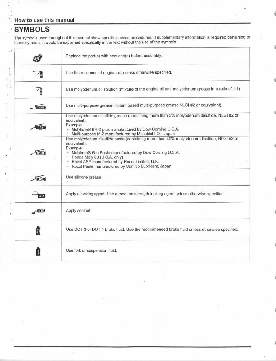
The symbols used throughout this manual show specific service procedures. If supplementary Information is required pertaining to
these symbols, it would be explained specifically in the text without the use of the symbols.
!lIl!~
Replace the partes) with new one{s) before assembly.
.....
-,
Use the recommend engine oil. unless otherwise specified.
,
Use molybdenum oi l solution (mixture of the engine oil and molybdenum grease In a ratio of 1: 1).
_ .s;;;., Use multi-purpose grease (lithium based multi-purpose grease NlGI #2 or equivalent).
Use molybdenum disulfide grease (containing more than 3% molybdenum disulfide, NLGI #2 or
equivalent).
~
Example:
• Molykote® BR-2 plus manufactured by Dow Corning U.S.A.
• Multl-purpose M·2 manufactured by Mitsublshi Oil, Japan
Use molybdenum disulfide paste (containing more than 40% molybdenum disulfide, NlGI #2 or
equivalent).
~
Example:
,
MoIykote® G·n Paste m~nufactured by Dow Coming U.S A
,
Honda Moly 60 (U . S.A. only)
·
Rocol ASP manufactured by Rocollimited, U.K.
·
Rocol Paste manufactured by Sumlco lubricant, Japan
~
Use silicone grease.
CU
Apply a locking agenl Use a medium strength locking agent unless otherwise specified.
~
Apply sealant.
I
Use DOT 3 or DOT 4 brake fluid. Use the recommended brake fluid unless otherwise specified.
8
Use fork: or suspension fluid.
•
4
4
I
I
I
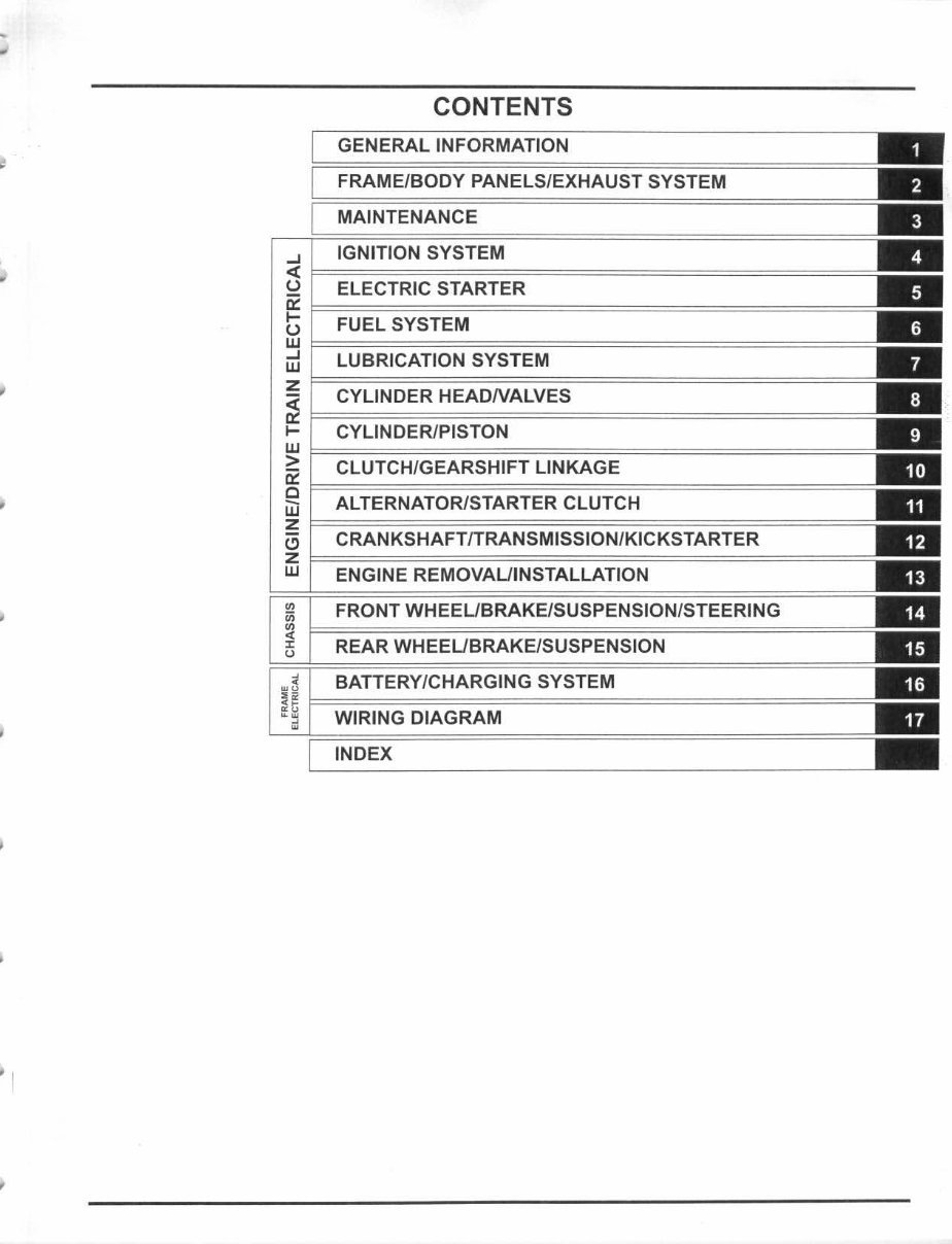
CONTENTS
GENERAL INFORMATION
FRAME/BODY PANELS/EXHAUST SYSTEM
MAINTENANCE
, IGNITION SYSTEM
~ F=~~~~~==~======================~
l.l ELECTRIC STARTER
~ F=~~~==~===========================
l.l FUEL SYSTEM
~ F=~~~~~~~~========================
LUBRICATION SYSTEM
~ F=========================================
- CYLINDER HEADNALVES
~ F===~~~================================
.... CYLINDER/PISTON
~ F=~~~~~~~~~~=================
CLUTCH/GEARSHIFT LINKAGE
~ F=~==~~~~~==~===================
iii ALTERNATOR/STARTER CLUTCH
z ~~~~~==~~~~~~~~~======
'" CRANKSHAFT/TRANSMISSION/KICKSTARTER
Z F=~~~~~~~~~~~===============
W ENGINE REMOVAUINSTALLATION
FRONT WHEEUBRAKE/SUSPENSION/STEERI NG
REAR WHEEUBRAKE /SUSPENSION
, BATTERY/CHARGING SYSTEM
!~ F=~~~~~========================
•• WIRING DIAGRAM
•
INDEX
MEMO
•
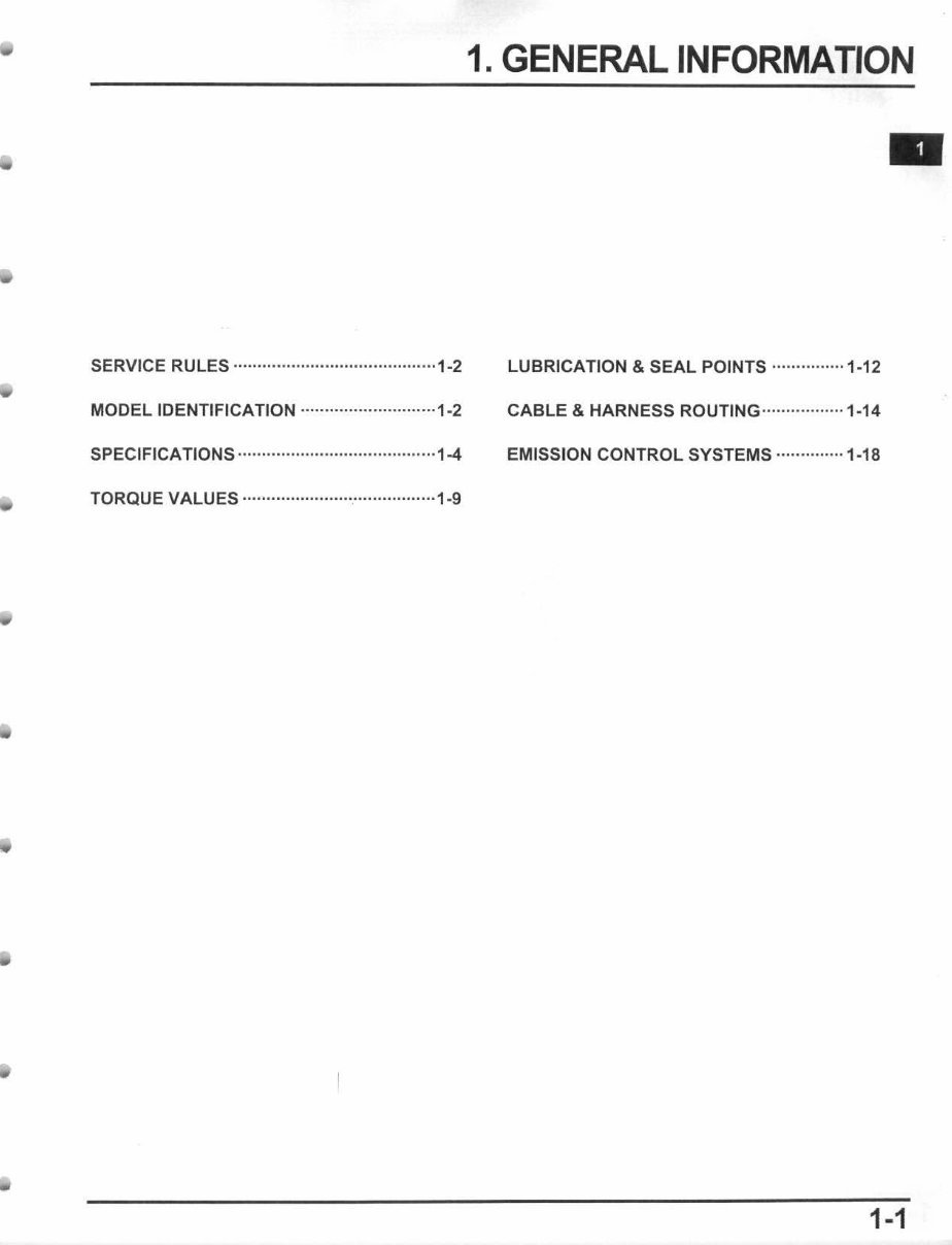
SERVICE RULES · ·· ··········· ·· ·· ························1-2
MODEL IDENTIFICATION ··· ·················· ·· ·· ··· 1-2
SPECIFICATIONS ·· ····················· ··· ···············1-4
TORQUE VALUES ······················ ·· ··········· .... ·1-9
1. GENERAL INFORMATION
LUBRICATION & SEAL POINTS ·· ············· 1-12
CABLE & HARNESS ROUTING····· ·· ·· ········ 1·14
EMISSION CONTROL SYSTEMS ··············1-18
1-1
GENERAL INFORMATION
SERVICE RULES
1. Use genuine Honda or Honda-recommended parts and lubricants or their equivalents. Parts Ihat don't meet Honda's design
specifications may cause damage to the motorcycle.
2. Use the speciallools designed for this product to avoid damage and incorrect assembly.
3. Use only metric tools when servicing Ihe motorcycle. Metric bolts, nuts and screws are not interchangeable with English
fasteners.
4. Install new gaskets, O-rings, cotter pins, and lock plates when reassembling.
5. When tightening bolts or nuts, begin with the larger diameter or inner bolt first. Then tighten to the specified torque diagonally in
incremental steps unless a particular sequence is specified.
6. Clean parts in cleaning solvent upon disassembly. Lubricate any sliding surfaces before reassembly.
7. After reassembly, check all parts for proper installation and operation.
8. Route all electrical wi res as shown in the Cable and Harness Routing (page 1-14).
ABBREVIATION
Throughout this manual, the following abbreviations are used to identify the respective parts or systems.
Ab brev. term
leM Ignition Control Module
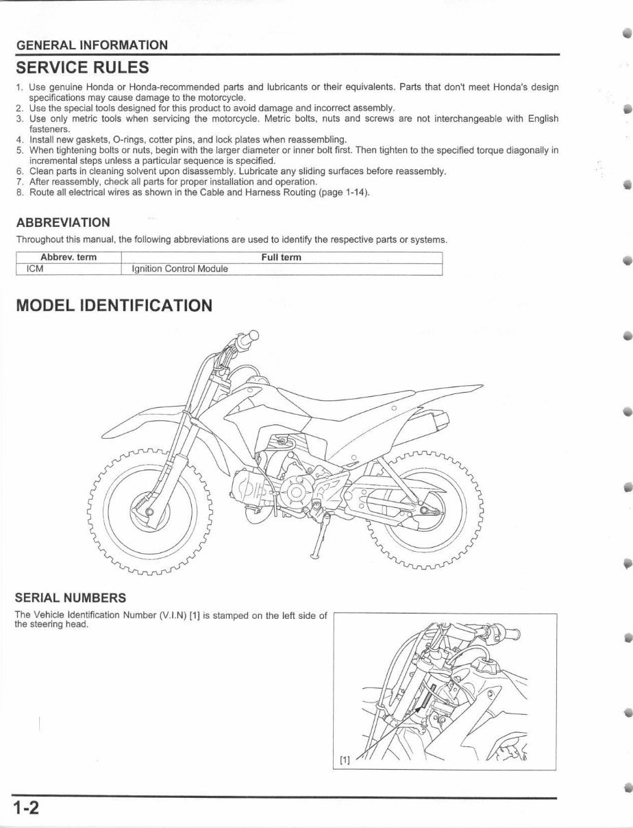
MODEL IDENTIFICATION
SERIAL NUMBERS
Full term
The Vehicle Identification Number (V.I.N) [1] is stamped on the left side of ,---- -- ---- -- -------,
the steering head.
11 I
1-2
•
•
•
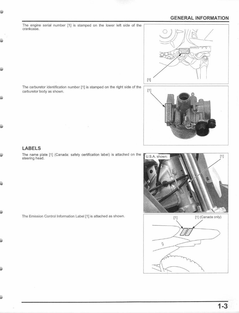
The engine serial number [1] is stamped on the lower left side of the
crankcase.
111
GENERAL INFORMATION
Th e carl::luretor identification number [1] is stamped on Ihe right side of the ~=================~
carburetor body as shown.
LABELS
The name plale [1) (C anada: safety certification label) is attached on the rc~-:--.,---
sleering head.
The Emission Conlrollnformalion Label [1] is attached as shown.
11 J
[1] (Canada only)
1-3
GENERAL INFORMATION
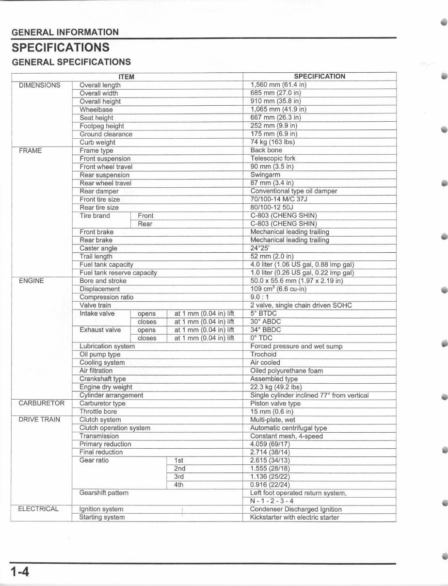
SPECIFICATIONS
GENERAL SPECIFICATIONS
1-4
i I
•
•
•
You're Reading a Preview
What's Included?
 Lifetime Access
Fast Download Speeds
Online & Offline Access
Access PDF Contents & Bookmarks
Full Search Facility
Print one or all pages of your manual
$31.99
2013-2015 CRF110F Service & Repair Manual
Viewed 78 Times Today

What's Included?
Lifetime Access
Fast Download Speeds
Online & Offline Access
Access PDF Contents & Bookmarks
Full Search Facility
Print one or all pages of your manual
$31.99

Secure transaction
What's Included?
Lifetime Access
Fast Download Speeds
Online & Offline Access
Access PDF Contents & Bookmarks
Full Search Facility
Print one or all pages of your manual
Description
Get your hands on the comprehensive repair manual for the 2013-2015 Honda CRF110F four-stroke youth bike. This manual covers everything from complete tear down and rebuild to pictures and part diagrams, torque specs, maintenance, troubleshooting, and more. With 264 pages, it's a valuable resource for both professional mechanics and DIY enthusiasts.
This manual features clickable chapters and is searchable, making it easy to locate the information you need. There are no restrictions on printing or saving/burning to disc, providing you with the flexibility to use the manual as needed.


