

1985-1991 CR500R Service & Repair Manual
What's Included?
Fast Download Speeds
Online & Offline Access
Access PDF Contents & Bookmarks
Full Search Facility
Print one or all pages of your manual
85-91
CR500R
-
-
-
-
-
-
-
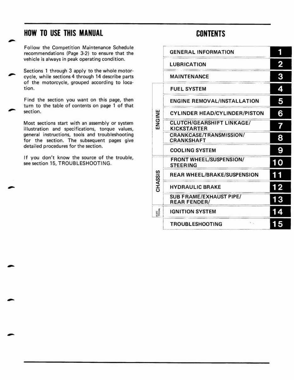
HOW TO USE THIS MANUAL
Follow the Competition Maintenance Schedule
recommendat io ns (Page 3-2) to ensure that the
vehicle is always in peak operating condition.
Sectio ns 1 through 3 apply to the whole motor-
cycle, while sections 4 through 14 describe parts
of the motorcycle, grouped according to loca-
tion.
Find the section you want on this page, then
turn to the table of contents on page 1 of that
section.
Most sections start with an assembly or system
illustration and specifications, torque values,
general instructions, tools and troubleshooting
for the section. The subsequent pages give
detailed procedures for the section.
I f you don't know the source of the trouble,
see section 15, TROUBLESHOOTING.
w
Z
Cl
Z
w
CONTENTS
[ ~ENERAL INFORMATION
~BRICATION
======
~ AINTENANCE
FUEL SYSTEM
ENGINE REMOVAL/ INSTALLATION
CYLINDER HEAD/CYLINDER/PISTON
COOLING SYSTEM
IGNITION SYSTEM
TROUBLESHOOTING
-
-
-
-
-
-
-
GEN ER A L SA FETY
SERVICE RU LE S
MOOEL IOENTIFICATION
SPECIF ICATI ONS
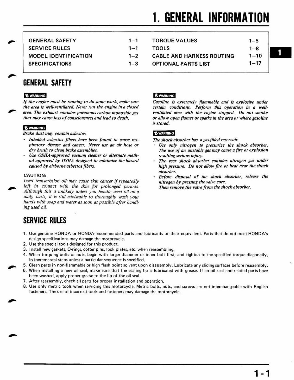
GENERAL SAFETY
I?JiJ.f; !ii fi!1
1- 1
1- 1
1- 2
1 -3
If the engine must be running 10 do some work, make sure
the area ;s well-ven/ilated. NetJer run the engine in Q closed
area. The exhaust contains poisonous carbon monoxide gas
thor may cause loss of consciousness and lead to death.
1A' ?li,i ii:!!J
Brake dust may contain asbestos.
[nhalled ashestos fibers have been found 10 rouse res-
piratory disease and Cflncer . Never use an ai, hose or
dry brush 10 clean broke assemblies.
Use OSHA-approved vacuum cleaner or alternate meth-
od approved by OSHA designed 10 minimize the hazard
caused by airborne ashestos flbers.
CAUTION:
Used transmission oil 'may cause skin cancer If repeatedly
left in contact with the skin for prolonged periods.
Although this is unlikely unless you handle used oil on a
daily basis, it is still adviseable to thoroughly wash your
hands with soap and water as soon as possible after handl-
ing used oil.
SERVICE RULES
1. GENERAL INFORMATION
TOR QUE VA LUES
TOOLS
CABLE ANO HARNE SS ROUTING
OPTIONAL PARTS LIST
IAWl;IiiiUN
1- 5
1- 8
1- 10
1- 17
Gasoline is eXlermely flammable and ls explos;"e under
certain conditio~. Perform this operation in a well-
"enrilated area with the engine slopped. Do not smoke
or allow open flames or sporks in Ihe area or where gasoline
is stored.
1 ''tih Wi ilN
The shock absorber has a gas-filled reservoir.
Use only nitrogen to pressurize the shock absorber.
The use of an unstable gas may cause a fire or explosion
resulting serious injury.
The rear shock absorber contains nitrogen gas u rl der
high pressure. Do not allow fire or heat near the shock
absorber.
Before disposal of the shock absorber, release the
nitrogen by pressing the "a/"e core.
Then remove the "alve from the shock absorber.
1. Use genuine HONDA or HONDA-recommended parts and lubricants or their equivalent. Parts that do not meet HONDA's
design specificat io ns may damage the motorcycle.
2. Use the special tools designed for this product.
3. Insta ll new gaskets, Q.rings, cotter pins, lock plates, etc. when reassem bl ing.
4.
5.
6.
7.
B.
Whe n torquing bolts or nuts, begin with larger-diameter or inne r bolt first, and t ighten to the specified torque diagonally,
in incremental steps unless a particular sequence is specified.
Clean parts in non·flammable or high flash point solvent upon di sassembly. Lubricate any sliding surfaces before reassembly.
When installing a new oil se a!, make sure that the sealing lip is lubricated wi th grease. It an oil seal and related parts have
been washed, app ly proper grease to the lip of the oil seal.
After reassembly, check all parts for proper insta llation and operat io n.
Use only metr ic too ls when servicing this motorcycle. Metric bolts, nuts, and screws are not interchangeable with English
fasteners. The use of incorrect tools and fasteners may damage the mot orcycle.
1 - 1
GENERAL INFORMATION
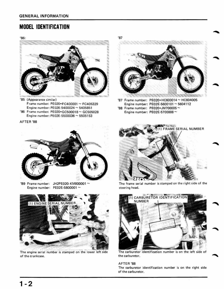
MODEL IDENTIFICATION
-~-- .. ...,.. - -
--- ---~
'85 (Appearance similar)
Frame number: PE020-FC400001 ,...., FC405329
Engine number: PE02E·5400024""" 5405851
'86 Frame number: PE020·GCSOOO1S ....... GC505028
Engine number: PE02E-5500036 ..... 5505153
AFTER'S8
'89 Frame number: JH2PEQ20· KMBOOOOl "-
Engine number: PE02E·5800001""'"
- ~-~- ---- -,-"-
Th e engine serial number is stamped on the lower
of the crankcase.
1-2
'87
'87 Frame number: PE020-HC600014 "" HC604QQ5
Engine number: PE02E-5600101 "'" 5604112
' S8 Frame number: PE020-JM700005 ""
Engine number: PE02E -57QOOOB """
•
•
,
•
"
The frame serial number is stamped on the right side of the
steering head.
the carburetor.
AFTER'S8
The carburetor identification number is on the right side
of the carburetor.
-
-
-
.....
GENERAL INFORMATION
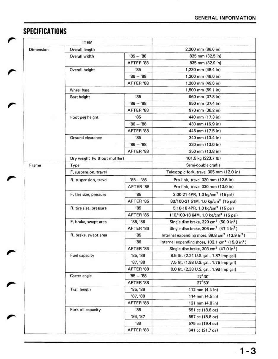
SPECIFICATIONS
ITEM
Dimension Overall length 2,200 mm (86.6 in)
Overall w i dth 'S5 - '88 825 mm (32.5 in)
AFTER '88 835 mm (32.9 in)
,... Overall hei ght 'S5 , .230 mm (48.4 in)
'86 - ' SS 1.200 mm (48.0 in)
AFTER ' S8 1,260 mm (49.6 in)
Wheel base 1,500 mm (59.1 in)
Seat height 'S5 960 mm (37.8 in)
,... '86 - '88 950 mm (37 .4 in)
A FTER 'S8 970 mm (38.2 in)
Foot peg height 'S5 440 mm (17.3 in)
'86 - '88 430 mm (16.9 in)
AFTER ' S8 445 mm (17.5 i n)
Ground ct earance 'S5 340 mm (13.4 i n)
'86 - '88 330 mm (13.0 i n)
AFTER '88 350 mm (13,8 in)
Dry wei ght (w ithout muff le r) 101.5kg (223.7 tbl
Frame Type Semi-double cradle
F. suspension, travel Telescopic fork , t r avel 305 mm (12.0 in)
R. suspension, travel '85 - '86 Pro-link, tra ve l 320 mm (12.6 in)
AFTE R' S8 Pro-link, tr avel 330 mm (13.0 in )
F. t ire si ze, pressure 'S5 3.00-21 4PR , 1.0 kg/cm
2
(15 psi )
A FTER '85 80/ 100.21 51M, 1.0 kg/cm
1
(15 psi)
R. t ire si z e, pre ssure 'S5 5.1o.184PR, 1.0kg/cm
1
(15 psi)
AFT ER '85 110/ 100·1864M, 1.0kg/cm
l
I 15psi )
F. brake, swept area '85, '86 Single d isc brake, 329 cm
1
(50.9 inl)
AFTER '86 Singl e disc brake, 306 cm
1
(47.4 inl)
R. brake, swep t area 'S5 Internal expanding s hoes , 89.8 cm
1
(13.9 in
1
)
'86 Internal expandi ng s hoes, 102.1 cm
1
(15.8 in
1
)
AFTER '86 Si ngle d isc brake , 303 cm
1
(47.0 inl )
Fu el capacity '85, '86 8.5 lit . (2 . 24 U.S. gat , 1.87 Imp gal)
'87, '88 7.SHt. 11 .98 U.S. gat , 1.75 Imp gal)
AFTER '88 9.0 lit. (2 .38 U.S. gat, 1.98 Imp gal)
Caster ang le 'S5 - 'SS
27
°
30
,
AFTER '88 27°50'
Trail length '85, '86 112 mm (4 .4 in)
'87, '88 11 4 mm (4 .5 in)
AFTER '88 121 mm (4 .8 i n)
Fork oi l capacit y 'S5 55 1 cc (18.6 oz l
'86, '87 557 cc (18.8 Ol )
'88 575 cc (19.4 al l
AFTER '88 641 cc (21.7 Ol)
1-3
GENERAL INFORMATION
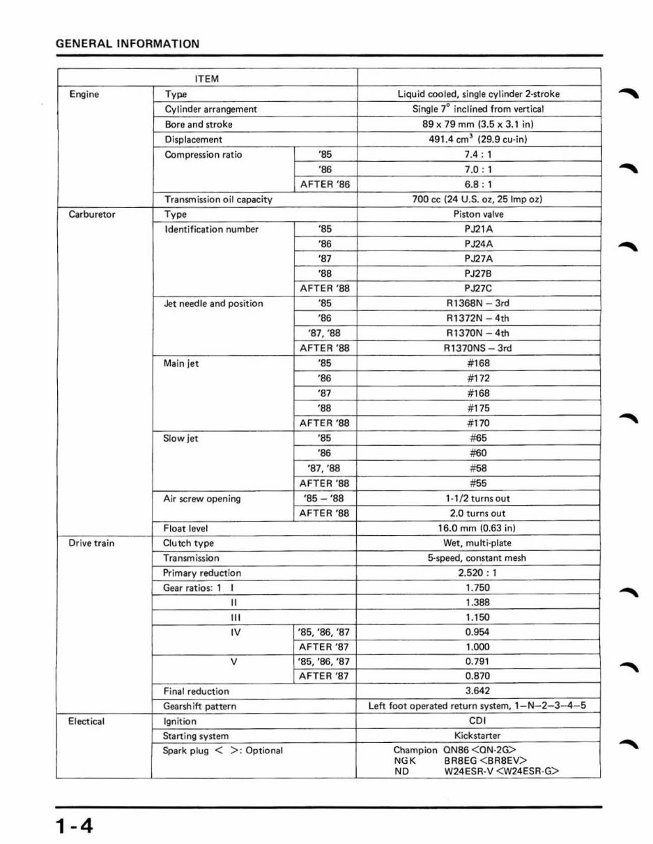
ITEM
Eng ine Type liquid cooled, single cylinder 2-stroke
Cylinder arrangement Single 7° inclined from vertical
Bore and stroke 89 x 79mm (3.5 x 3.1 in)
Displacement 491.4 em
3
(29.9 cu·in)
Compression ratio '85 7.4 : 1
'86 7.0 : 1
AFTER '86 6.8 : 1
Transm ission oil capacitY 700 cc (24 U.S. OZ, 25 Imp ell
Carburetor Type Pis ton va lve
Identification number '85 PJ21A
'86 PJ24A
-
'87 PJ27A
'88 PJ27B
AFTER '88 PJ27 C
Jet needle and position '85 R1368N - 3rd
'86 R1372N - 4th
'S7. '88 R1370N 4th
AFTER '88 R 1370NS - 3rd
Main jet '85 # 168
'86 #172
'87 # 168
'88 # 175
AFTER'S8 # 170
Slow jet '85 #65
'86 #60
'S7. ' 88 #58
AFTER '88 #55
Ajr screw opening '85 - '8 8 1·1/2 turns out
AFTER '88 2.0 turns out
Float level 16.0 mm (0.63 in)
Dr ive train Clutch type Wet. multi -plate
Transmission &speed. constant mesh
Primary reduct ion 2.520 : 1
Gear ratios: 1
,
1.750
II 1.388
"'
1.150
'V
'85, '86, '87 0.954
AFTER '87 1.000
V '85, '86, '87 0.791
AFTER '87 0.870
Fin al reducti on 3.642
Gearsh i tt pattern L ett foot operated return system. l - N- 2- 3-4 -5
Electical Ign itio n CO,
Starting system Kickstarter
Spark plug < >: Optional Champion ON86 < ON ·2 G>
-
NGK BRBEG < BR8EV>
NO W24ESR·V <W24ESR·G>
1-4
GENERAL INFORMATION
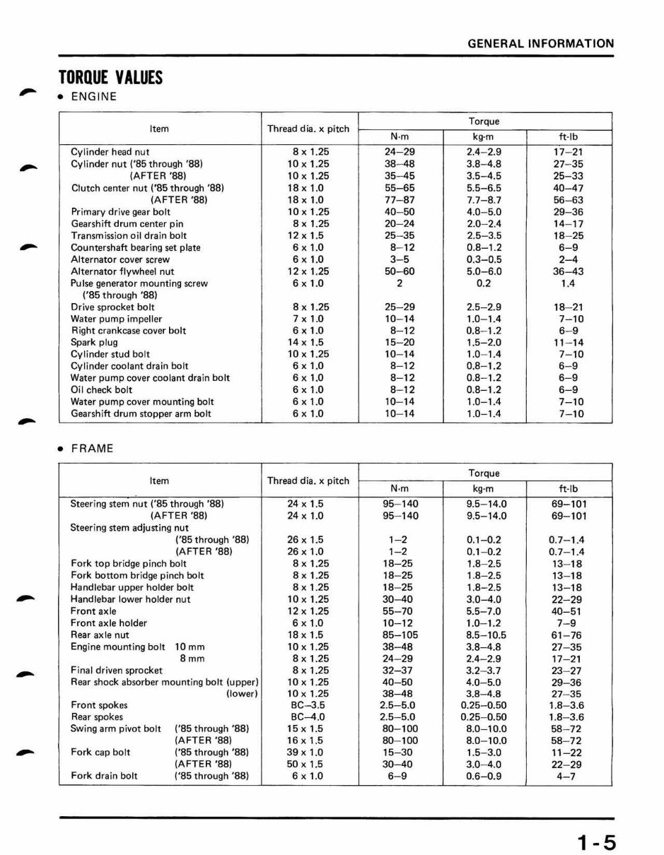
TORQUE VALUES
-
• ENGINE
Item Thread dia. x pitch
Torque
N·m kg·m ft·lb
Cylinder head nut 8 x 1.25 24 29 2.4- 2.9 17 21
-
Cylinder nut ('85 through '88) 10xl .25 38-48 3.8-4.8 27-35
(AFTER'S8) 10 x 1.25 35-45 3.5-4.5 25-33
Clutch center nut ('85 through '88) 1exT .a 55-65 5.5-6.5 40 -47
(AFTER '88) 18x1.0 77- 87 7.7-8.7 56- 63
Primary drive gear bolt 10 x 1.25 40- 50 4.0- 5.0 29-36
Gearshift drum center pin 8 x 1.25 20-24 2.0- 2.4 14- 17
Transmission oil drain bolt 12x l .S 25- 35 2.5-3.5 18- 25
-
Countershaft bearing set plate 6 x 1.0 8- 12 0.8- 1.2 6-9
Alternator cover screw 6 x 1.0 3-5 0.3-0.5 2-4
Alternat or flywheel nut 12 x 1. 25 50 - 60 5.0-6.0 36- 43
Pulse generator mounting screw 6 x 1.0 2 0.2
'"
('85 through '88)
Drive sprocket bolt 8 x 1. 25 25-29 2.5-2.9 18- 21
Water pump impeller 7 x 1.0 10- 14 1.0- 1.4 7- 10
Right crankcase cover bolt 6 x 1.0 8-12 0.8- 1.2 6-9
Spark plug 14 x 1.5 15-20 1.5-2.0 11 - 14
Cylinder stud bolt 10 x 1.25 10- 14 1.0- 1.4 7-10
Cylinder coolant drain bolt 6 x 1.0 8- 12 0.8-1.2 6- 9
Water pump cover coolant drain bolt 6 x 1.0 8-12 0.8 - 1.2 6-9
Oil check bolt 6 x 1.0 8- 12 0.8- 1.2 6- 9
Water pump cover mounting bolt 6 x 1.0 10- 14 1.0- 1.4 7- 10
-
Gearshift drum stopper arm bolt 6 x 1.0 10- 14 1.0- 1.4 7- 10
• FRAME
Item Thread dia. x pitch
Torque
N·m kg·m ft-Ib
Steering stem nut ('85 through '88) 24 x 1.5 95-140 9.5 14.0 69 101
(AFTER '88) 24 x 1. 0 95- 140 9.5-14.0 69- 101
Steering stem adjusting nut
('85 through '88) 26 x 1.5 1- 2 0.1-0 .2 0 .7-1.4
(A FTER '88) 26 x 1.0 1- 2 0.1 - 0.2 0.7- 1.4
Fork top bridge pinch bolt 8 x 1.25 18-25 1.8- 2.5 13- 18
Fork bottom bridge pinch bolt 8 x 1.25 18-25 1.8- 2.5 13- 18
Handlebar upp er ho lder bolt 8 x 1.25 18- 25 1.8-2 .5 13- 18
-
Handlebar lower holder nut lOx 1. 25 30-40 3.0 -4 .0 22-29
Front axle 12 x l.25 55-70 5.5-7.0 40- 51
Front axle holder 6 x 1. 0 10- 12 1.0- 1. 2 7- 9
Rear ax Ie nut 18 x 1.5 85- 105 8.5- 10.5 61 - 76
Eng ine mount ing bolt 10 mm 10 x 1.25 38- 48 3.8-4.8 27- 35
Bmm 8 x 1.25 24 - 29 2.4 -2. 9 17-2 1
-
Final driven sprocket 8 II 1.25 32-37 3.2-3.7 23- 27
Rear shock absorber mounting bolt (upper) 10 x 1.25 40-50 4.0- 5.0 29 -36
(lower) 10 x 1. 25 38-48 3.8- 4.8 27- 35
Front spokes BC-3.5 2.5- 5.0 0.25-0.50 1.8- 3.6
Rear spokes BC-4.0 2.5- 5.0 0.25- 0.50 1.8- 3.6
SWing arm pivot bolt ('85 th rough '8 8) 15x1.5 80- 100 8.0- 10.0 58- 72
(AFT ER '88) 16xl .5 80-100 8.0- 10.0 58- 72
-
Fork cap bolt ('85 through '88) 39xl.0 15-30 1.5-3.0 11 -22
(AF TER '88) 50 x 1.5 30-40 3.0-4 .0 22- 29
Fork dra in bolt ('85 through '88) 6 x 1.0 6-9 0.6-0.9 4- 7
1-5
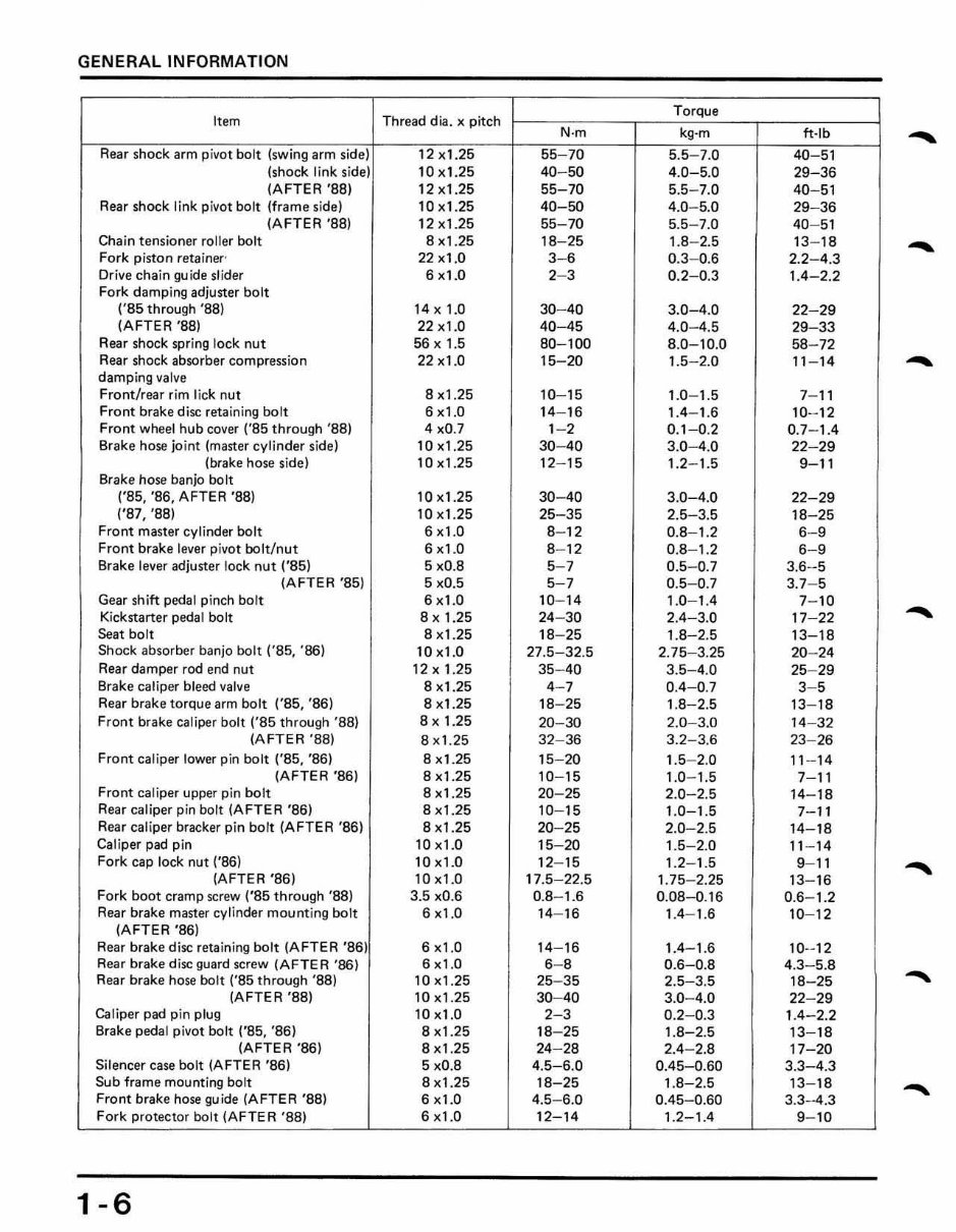
GENERAL INF ORMATION
Item Thread dia. x pitch
Torque
N·m kg·m ft·rb
-
Rear shock arm pivot bo lt (swing arm side) 12)( 1. 25 55 70 5.5-7.0 40-5 1
(shock link side) 10x 1.25 40- 50 4.0-5 .0 29-36
IA FTE R '881 12x1 .25 55-70 5.5- 7.0 40-5 1
Rear shock link pivot bolt (frame side) 10 x 1. 25 40-50 4.0- 5.0 29- 36
(AFT ER'S8) 12 x1.25 55-70 5.5- 7.0 40- 51
Chain tensioner ro ll er bolt 8 x1.25 1 8-25 1.8-2.5 13- 18
Fork piston retainer- 22 )( 1.0 3- 6 0.3-0.6 2.2- 4.3
-
Or; ve chain guide slider 6 x l .0 2- 3 0.2-0.3 1.4-2.2
Fork damping adjuster bolt
('85 through '88) 14)(1.0 30-40 3.0- 4.0 22-29
(AFTER'S8) 22 )(1.0 40-45 4.0- 4.5 29- 33
Rear shock spring lock nut 56 x 1.5 80- 100 8.0-10.0 58- 72
Rear shock absorber compression 22 xl .0 15 -20 1. 5- 2.0 11 -1 4
-
damping valve
Front/rear rim lick nut 8 x1.25 10- 15 1.0- 1.5 7- 11
Fr ont brake disc retaining bolt 6 xl.0 14- 16 1.4 - 1.6 10- 12
F ront wheel hub cover ('85 th rough '88) 4 xO.7 1- 2 0.1-0. 2 0.7- 1.4
Brake hose jOint (master cylinder side) 10 xl.25 30-40 3.0-4.0 22-29
(brake hose side) 10x1.25 12- 15 1.2- 1.5 9-1 1
Brake hose banjo bolt
('85, '86, AFTER '88) 10x l. 25 30 - 40 3.0 - 4.0 22-29
1 ' 87, '881 10x l .25 25-35 2.5 -3. 5 18-25
Front master cylinder bolt 6 x l .0 8- 12 0.8- 1. 2 6-9
Front brake lever pivot IXllt/nut 6 x1.0 8- 12 0.8- 1. 2 6-9
Brake lever adjuster lock nut ('85) 5 xO.8 5- 7 0.5-0.7 3.6-5
(AFTER '85) 5 xO.5 5-7 0 .5-0.7 3.7- 5
Gear shift pedal pinch bolt 6 x l. 0 10- 14 1.0- 1.4 7- 10
Kickstarter pedal bolt 8 x 1.25 24- 30 2.4-3.0 17-22
-
Seat bolt 8x1.25 18- 25 1.8-2.5 13- 18
Shock absorber banjo bolt ('85, '86) 10 xl.0 27.5-32.5 2.75- 3.25 20- 24
Rear damper rod end nut 12 x 1.25 35 -40 3.5-4.0 25-29
Brake caliper bleed va lve 8 x l. 25 4- 7 0.4- 0.7 3-5
Rear brake torque arm bolt ('85, '86) 8 xl .25 18- 25 1 .8-2.5 13- 18
Front brake caliper bolt ('85 through '88) 8xl.25 20-30 2.0- 3.0 14- 32
(AFTER '88) 8x1.25 32 - 36 3.2-3.6 23- 26
Front caliper lower pin bolt ('85, '86) 8 x1.25 15- 20 1. 5- 2.0 11 - 14
(AFTER '86) 8 x1.25 10- 15 1 .0 - 1. 5 7- 11
Front caliper upper pin bolt 8 xl.25 20-25 2.0-2.5 14-18
Rear caliper pin bolt (A FT ER '86) 8 xl .25 10- 15 1.0- 1.5 7- 11
Rea r caliper bracker pin bolt (A FT ER '86) 8 x1.25 20- 25 2.0- 2.5 14- 18
Caliper pad pin 10 x1.0 15- 20 1.5- 2.0 11- 14
Fork cap lock nut ('86) 10 x l.0 12- 15 1.2- 1.5 9- 11
(A FT ER '86) 10 x 1.0 17.5- 22.5 1.75-2.2 5 13-16
- Fork boot cramp screw ('85 th rough '88) 3.5 xO.6 0.8- 1.6 0. 08-0.16 0.6- 1.2
Rear brake master cylinder mounting bolt 6 xl.0 14- 16 1.4- 1.6 10- 12
(AFTER '86)
Rear brake disc retaining bolt (A FTER '86) 6 xl.0 14- 16 1.4- 1.6 10--12
Rear brake d isc guard screw (AF TE R '86) 6 xl.0 6- 8 0. 6-0.8 4.3- 5.8
Rear brake hose bolt ('85 through '88) 10 xl.25 25- 35 2.5-3.5 18- 25
(A FTE R '88) 10 x1.25 30-40 3.0-4 .0 22- 29
Caliper pad pin plug 10 x1.0 2-3 0.2- 0.3 1. 4- 2.2
Brake pedal pivot bolt ('85, '86) 8x1.25 18- 25 1.8-2.5 13- 18
(A FT ER '86) 8 xt.25 24-28 2.4- 2.8 17- 20
Silencer case bolt (AFTER '86) 5 xO.8 4.5- 6.0 0.45-0.60 3.3-4.3
Sub frame mounting bolt 8 xl.25 18-25 1.8-2.5 13- 18
Front brake hose guide (A FTE R '88) 6 x1.0 4.5- 6.0 0.45- 0.60 3.3--4.3
For k protector bolt (AFTER '88) 6 xl.0 12- 14 1.2- 1. 4 9- 10
1-6
-
-
-
-
-
-
GENERAL INFORMATION
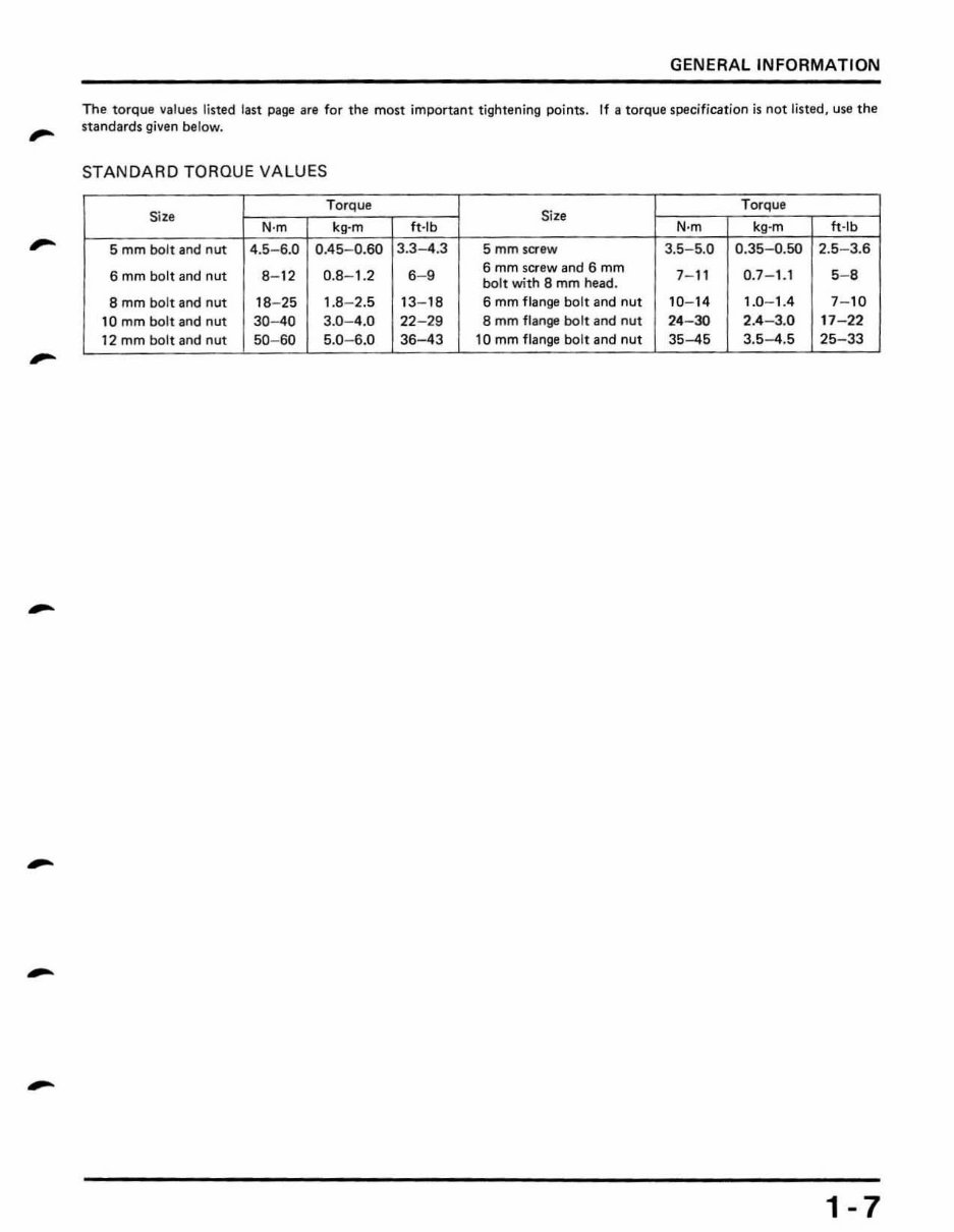
The torque values li sted last page a re for the most important tightening points. If a torque specification is not listed , use the
standards given be low.
STANDARD TORQUE VA LUES
Si ze
TorQue
Size
Torque
N·m kg -m ft -rb N·m kg -m ft -rb
5 mm bolt and nut 4.5- 6.0 0.45- 0.60 3.3--4.3 5 mmsaew 3.5 - 5.0 0.35- 0.50 2.5- 3.6
6 mm bolt and nut 8- 12 0.8- 1.2 6- 9
6 mm screw and 6 mm
7- 11 0.7- 1.1 5- 8
bolt with 8 mm head.
S mm bolt and nut 18- 25 1.8- 2.5 13 - 18 6 mm flange bolt and nut 10- 14 1.0- 1.4 7- 10
10 mm bolt and nut 30-40 3.0 - 4.0 22-29 8 mm flange bolt and nut 24 -30 2.4 - 3.0 17 - 22
12 mm bolt and nut 50- 60 5.0- 6.0 36--43 10 mm flange bolt and nut 35--45 3.5--4.5 25- 33
1-7
GENERAL INFORMATION
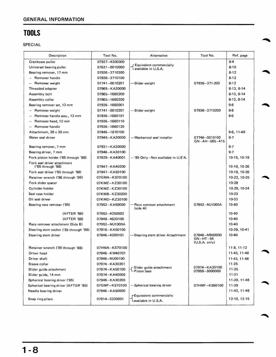
TOOLS
-
SPECI AL
Description Tool No. Alternative T ool No. Ref. pag!!
Crankcase puller 07937-4300000 84
Universal bearing pLlller 07631-00 10000
-{ Equivalent commercially
8-10
available in U.S.A.
Bearing remover, 17 mm 07936-37 10300 8·12
-
- Remover handle 07936 - 3710100 .. 12
- Remover weight 07741 - 0010201 -Slider weight 07936 - 37 1-200 8·12
Th readed adapter 07965- KA30000 8-13,8· 14
Assembly boll 07965- 1660200 8·13,8·14
Assembly collar 07965- 1660300 8·13,8-14
Bearing remover set, 12 mm 07936 -166000 1 g~
-
- Rl!rTlover weigtH 0774 1-00 10201 - Slider weight 07936-3710200 g~
- Remover handle assy., 12 mm 07936 - 1660 10 1 g-6
- Remover head, 12 mm 07936 -1660 110
- Remover handle 07936 -1660120
Atlachmenl, 28 K 30 mm 07946 -1870 100 9-6, 11 49
Waler seal driver 07945- KA30000 - Methanita! sea! insta!!e, 07746-0010100
g.,
GN - AH-065-415
Searing remover, 7 mm 07931-KA30000
,.,
Bearing driver, 7 mm 07946-KA301oo
g.,
Fork piston holder t'BS Ihrough 'B8) 07929-KA40001 -'85 On ly -Not available in U.S'A. 10·15,10·19
Fork seal dr iver al1achment
('B5lhrough 'B8) 07947 - KA402oo 10·19,10·26
Fork seal driver ("B5 through '88) 07947-KA501oo 10·19,10·26
Retainer wrench rB6 Ihrough '8B) 07GMA - KS70100 10·22,10·25
--
Fork Slider spacer 07KMZ - KZ30100 10·28
Cylinde r holder 07KMZ - KZ30100 10· 29, 10-34
Seal case holder 07KMB - KZ30200 10·33
Oil seal driver 07KMD-KZ30 1oo 10 ·33
Bearing race remover ("B5) 07953-KASOOOO - Race remover al1achment
(side A)
07953 -MJl oo0A 10-40
(AFTER '86) 07953-4250002 10-40
(AFTE R '88) 07948 - 4630100 10-40
Race remover HI18chment (Side B) 07953 - MJ 1000A 10-40
Steering stem socket ('B5 through 'BB) 07916 - KA50 1oo 10-39,10-4 1
Steering stem driver 07946--4300 101 - Steering stem driver Attachment 07946 - MBOOOOO 10-40
GN-HT - 54
(U.S.A. only)
Retainer wrench (·B5 through ·88) 07HMA -K S70100 11·8, 11 ·12
Driver head 07946 - KM40701 11-43. 11 - 48
Driver shaft 07946-MJooloo 11-4 3.11·48
Sleeve collar 07974-KA30201 11-25
Slider guide altachme-nt 07974-KA501oo
-{Slider guide attachment 07974-KA301oo
11·25
Piston base 07958-3000000
Slider guide, 14 mm 07974 - KA4 0000 11 -3 1
Spherical bearing driver (·S5) 07946 - KA30200 11 -39.11-48
Spherical bearing driver (AFTER ·B5) 07GMF-KS70 100 - Spherical bearing driver 07HMF-KS60100 11 -39
-- Needle bearing driver 07946 - KASOOoo 11-43.11-48
Snap ring pliers 07914 - 3230001
{EquiValent commercially
available in U.S.A.
12· 10,12-15
-
1-8
You're Reading a Preview
What's Included?
Fast Download Speeds
Online & Offline Access
Access PDF Contents & Bookmarks
Full Search Facility
Print one or all pages of your manual
$31.99
Viewed 15 Times Today


Secure transaction
What's Included?
Fast Download Speeds
Online & Offline Access
Access PDF Contents & Bookmarks
Full Search Facility
Print one or all pages of your manual
$31.99
This repair manual covers the 1985-1991 Honda CR500R two-stroke bike, providing comprehensive information on complete tear down and rebuild, torque specs, maintenance, troubleshooting, and more. With 259 pages, it includes clickable chapters and is searchable for easy access to the desired information. There are no restrictions on printing or saving the manual.
This manual is a valuable resource for both professional mechanics and DIY enthusiasts, offering detailed insights into various aspects of the Honda CR500R bike.


