1-1 1 1. GENERAL INFORMATION SERVICE RULES ········································· 1-2 MODEL IDENTIFICATION··························· 1-3 GENERAL SPECIFICATIONS······················ 1-5 LUBRICATION SYSTEM SPECIFICATIONS········································ 1-7 FUEL SYSTEM (PGM-FI) SPECIFICATIONS········································ 1-7 COOLING SYSTEM SPECIFICATIONS ······ 1-7 CYLINDER HEAD/VALVES SPECIFICATIONS········································ 1-8 CLUTCH/STARTER CLUTCH SPECIFICATIONS········································ 1-8 TRANSMISSION/GEARSHIFT LINKAGE SPECIFICATIONS········································ 1-9 CRANKCASE/CRANKSHAFT/BALANCER/ PISTON/CYLINDER SPECIFICATIONS ······ 1-9 FRONT WHEEL/SUSPENSION/STEERING SPECIFICATIONS ····································· 1-10 REAR WHEEL/SUSPENSION SPECIFICATIONS ····································· 1-10 HYDRAULIC BRAKE SPECIFICATIONS··· 1-11 BATTERY/CHARGING SYSTEM SPECIFICATIONS ····································· 1-11 IGNITION SYSTEM SPECIFICATIONS ···· 1-11 ELECTRIC STARTER SPECIFICATIONS ·· 1-11 LIGHTS/METERS/SWITCHES SPECIFICATIONS ····································· 1-12 STANDARD TORQUE VALUES··············· 1-13 ENGINE & FRAME TORQUE VALUES ···· 1-13 LUBRICATION & SEAL POINTS ·············· 1-20 CABLE & HARNESS ROUTING ··············· 1-23 EMISSION CONTROL SYSTEMS ············ 1-42
GENERAL INFORMATION 1-2 GENERAL INFORMATION SERVICE RULES 1. Use genuine Honda or Honda-recommended parts and lubricants or their equivalents. Parts that don't meet Honda's design specifications may cause damage to the motorcycle. 2. Use the special tools designed for this product to avoid damage and incorrect assembly. 3. Use only metric tools when servicing the motorcycle. Metric bolts, nuts and screws are not interchangeable with English fasteners. 4. Install new gaskets, O-rings, cotter pins, and lock plates when reassembling. 5. When tightening bolts or nuts, begin with the larger diameter or inner bolt first. Then tighten to the specified torque diagonally in incremental steps unless a particular sequence is specified. 6. Clean parts in cleaning solvent upon disassembly. Lubricate any sliding surfaces before reassembly. 7. After reassembly, check all parts for proper installation and operation. 8. Route all electrical wires as shown in the Cable and Harness Routing (page 1-23). ABBREVIATION Throughout this manual, the following abbreviations are used to identify the respective parts or systems. Abbrev. term Full term PGM-FI Programmed Fuel Injection MAP sensor Manifold Absolute Pressure sensor TP sensor Throttle Position sensor ECT sensor Engine Coolant Temperature sensor IAT sensor Intake Air Temperature sensor CKP sensor Crankshaft Position sensor VS sensor Vehicle Speed sensor IACV Idle Air Control Valve ECM Engine Control Module EEPROM Electrically Erasable Programmable Read Only Memory DLC Data Link Connector SCS connector Service Check Short connector HDS Honda Diagnostic System DTC Diagnostic Trouble Code MIL Malfunction Indicator Lamp FP Fuel Pump PAIR Pulsed Secondary Air Injection ABS Anti-lock Brake System HISS Honda Ignition Security System
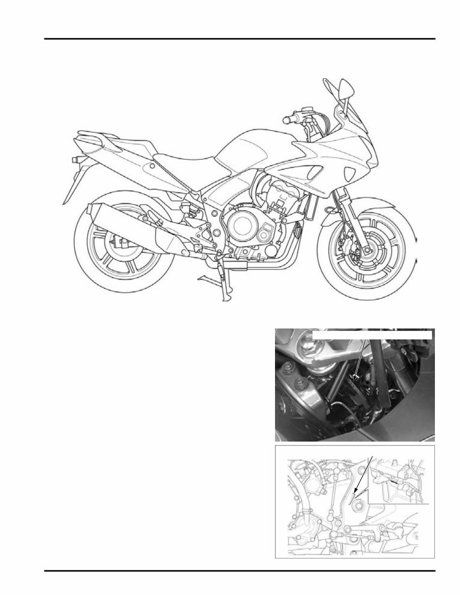
GENERAL INFORMATION 1-3 MODEL IDENTIFICATION CBF1000A Shown: SERIAL NUMBERS The Vehicle Identification Number (V.I.N) is stamped on the right side of the steering head. The engine serial number is stamped on the lower side of the lower crankcase. VEHICLE IDENTIFICATION NUMBER ENGINE SERIAL NUMBER
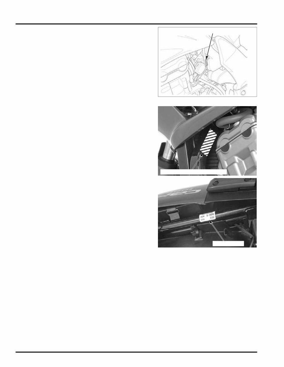
GENERAL INFORMATION 1-4 The throttle body identification number is stamped on the intake side of the throttle body as shown. LABELS The Model Identification Label is located on left side of the frame tube. The color label is attached as shown. When ordering color-coded parts, always specify the designated color code. THROTTLE BODY IDENTIFICATION NUMBER MODEL IDENTIFICATION LABEL COLOR LABEL
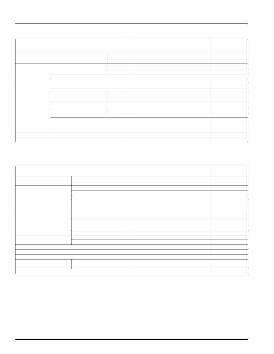
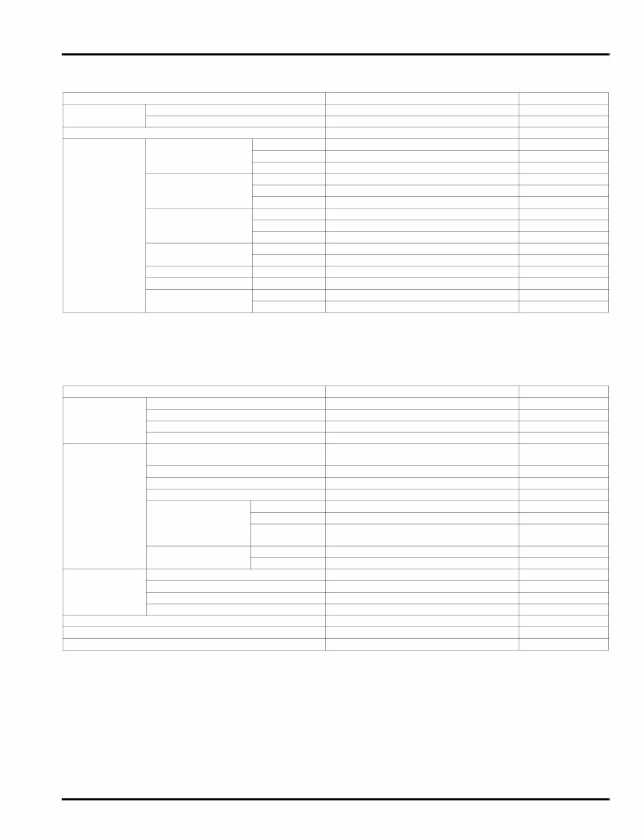
GENERAL INFORMATION 1-5 GENERAL SPECIFICATIONS ITEM SPECIFICATIONS DIMENSIONS Overall length 2,156 mm (84.9 in) Overall width 782 mm (30.8 in) Overall height 1,238 mm (48.7 in) Wheelbase 1,483 mm (58.4 in) Seat height 800 mm (31.5 in) Ground clearance 130 mm (5.1 in) Curb weight CBF1000: 244 kg (538 lbs) CBF1000A: 251 kg (553 lbs) Maximum weight capacity 195 kg (430 lbs) FRAME Frame type Diamond type Front suspension Telescopic fork Front axle travel 108 mm (4.3 in) Rear suspension Swingarm Rear axle travel 120 mm (4.7 in) Front tire size 120/70ZR17M/C (58W) Rear tire size 160/60ZR17M/C (69W) Front tire brand Bridgestone BT57F RADIAL U Michelin Pilot ROAD B Rear tire brand Bridgestone BT57R RADIAL E Michelin Pilot ROAD A Front brake Hydraulic double disc Rear brake Hydraulic single disc Caster angle 26° 00’ Trail length 111 mm (4.4 in) Fuel tank capacity 19.3 liter (5.1 US gal, 4.2 lmp gal) ENGINE Cylinder arrangement 4 cylinders in-line, inclined 28° from vertical Bore and stroke 75.0 x 56.5 mm (2.95 x 2.22 in) Displacement 998.4 cm 3 (60.92 cu-in) Compression ratio 11.0 : 1 Valve train Chain driven, DOHC Intake valve opens: at 1 mm (0.04 in) lift 15° BTDC closes: at 1 mm (0.04 in) lift 15° ABDC Exhaust valve opens: at 1 mm (0.04 in) lift 25° BBDC closes: at 1 mm (0.04 in) lift 5° ATDC Lubrication system Forced pressure and wet sump Oil pump type Trochoid Cooling system Liquid cooled Air filtration Paper element Engine dry weight 66.5 kg (146.6 lbs) Firing order 1 - 2 - 4 - 3 FUEL DELIVERY SYSTEM Type PGM-FI (Programmed Fuel Injection) Throttle bore 36 mm (1.4 in) DRIVE TRAIN Clutch system Multi-plate, wet Clutch operation system Hydraulic operating Transmission Constant mesh, 6-speeds Primary reduction 1.604 (77/48) Final reduction 2.687 (43/16) Gear ratio 1st 2.714 (38/14) 2nd 1.941 (33/17) 3rd 1.578 (30/19) 4th 1.363 (30/22) 5th 1.217 (28/23) 6th 1.115 (29/26) Gearshift pattern 1 - N - 2 - 3 - 4 - 5 - 6
GENERAL INFORMATION 1-6 ELECTRICAL Ignition system Computer-controlled digital transistorized with electric advance Starting system Electric starter motor Charging system Triple phase output alternator Regulator/rectifier FET shorted/triple phase, full wave rectifica- tion Lighting system Battery ITEM SPECIFICATIONS
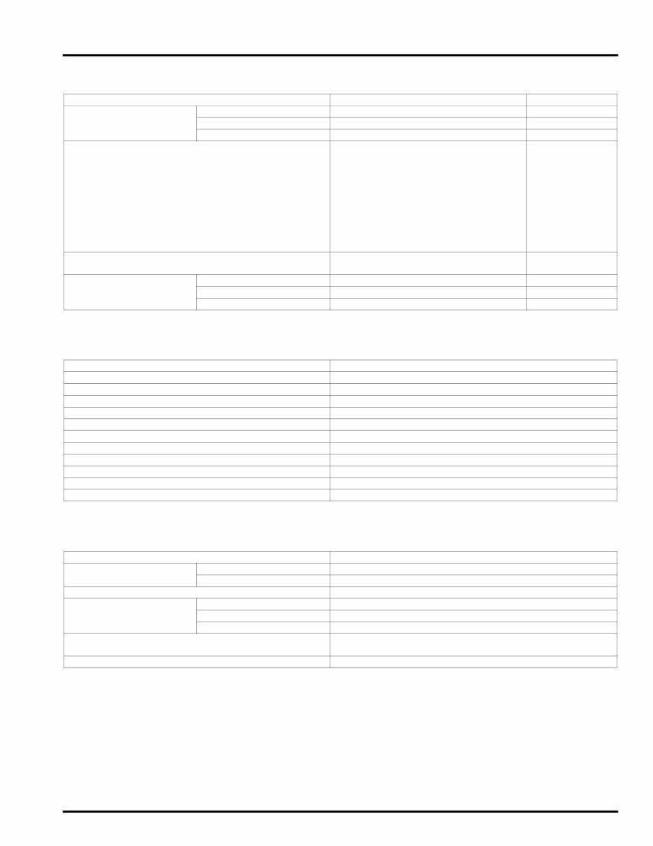
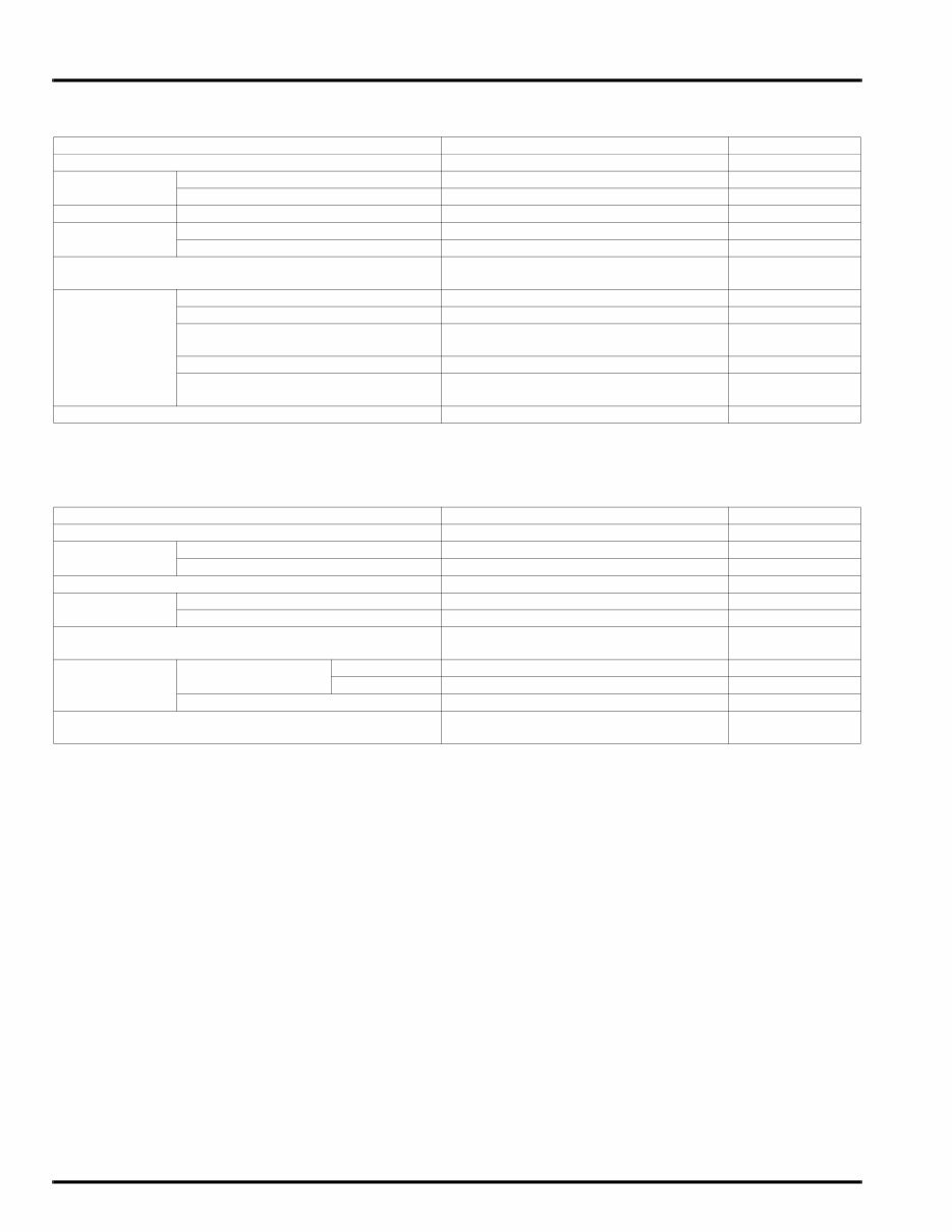
GENERAL INFORMATION 1-7 LUBRICATION SYSTEM SPECIFICATIONS Unit: mm (in) FUEL SYSTEM (PGM-FI) SPECIFICATIONS COOLING SYSTEM SPECIFICATIONS ITEM STANDARD SERVICE LIMIT Engine oil capacity After draining 2.7 liter (2.9 US qt, 2.4 lmp qt) – After oil filter change 3.5 liter (3.7 US qt, 3.1 lmp qt) – After disassembly 3.6 liter (3.8 US qt, 3.2 lmp qt) – Engine oil Suggested oil: – Honda "4-stroke motorcycle oil" or an equivalent Oil recommendation: API classification: SG or higher (except oils labeled as energy con- serving on the circular API service label) Viscosity: SAE 10W-30 JASO T 903 standard: MA Oil pressure at EOP (engine oil pressure) switch 510 kPa (5.2 kgf/cm 2 , 74 psi) at 6,000 min -1 (rpm)/(80°C/176°F) – Oil pump Tip clearance 0.15 (0.006) 0.20 (0.008) Body clearance 0.15 – 0.21 (0.006 – 0.008) 0.35 (0.014) Side clearance 0.04 – 0.09 (0.002 – 0.004) 0.17 (0.007) ITEM SPECIFICATIONS Throttle body identification number GQ3BA Idle speed 1,200 ± 100 min -1 (rpm) Throttle grip free play 2 – 6 mm (1/12 – 1/4 in) IAT sensor resistance (at 20°C/68°F) 1 – 4 kΩ ECT sensor resistance (at 20°C/68°F) 2.3 – 2.6 kΩ Fuel injector resistance (at 20°C /68°F) 11.1 – 12.3 Ω PAIR control solenoid valve resistance (at 20°C/68°F) 23 – 27 Ω CKP sensor peak voltage (at 20°C/68°F) 0.7 V minimum Manifold absolute pressure at idle 29 – 32 kPa (0.30 – 0.33 kgf/cm 2 , 4.3 – 4.7 psi) Fuel pressure at idle 343 kPa (3.5 kgf/cm 2 , 50 psi) Fuel pump flow (at 12 V) 189 cm 3 (6.4 US oz, 6.7 lmp oz) minimum/10 seconds ITEM SPECIFICATIONS Coolant capacity Radiator and engine 2.71 liter (2.86 US qt, 2.38 lmp qt) Reserve tank 0.30 liter (0.32 US qt, 0.26 lmp qt) Radiator cap relief pressure 108 – 137 kPa (1.1 – 1.4 kgf/cm 2 , 16 – 20 psi) Thermostat Begin to open 80 – 84 °C (176 – 183 °F) Fully open 90 °C (194 °F) Valve lift 8 mm (0.3 in) minimum Recommended antifreeze High quality ethylene glycol antifreeze containing corrosion protection inhibitors Standard coolant concentration 1:1 mixture with distilled water
The CBF1000-ABS Service Manual is an essential resource for anyone involved in the maintenance and repair of CBF1000-ABS motorcycles. This comprehensive manual provides detailed information on the procedures, tools, and specifications required to service the CBF1000-ABS model.
Whether you are a professional mechanic or a DIY enthusiast, this manual offers valuable insights into the inner workings of the CBF1000-ABS, enabling you to perform tasks ranging from routine maintenance to complex repairs with confidence.
With its clear and concise instructions, the CBF1000-ABS Service Manual serves as a reliable reference for troubleshooting, disassembly, reassembly, and adjustments, ensuring that the motorcycle is maintained to the highest standards.
By utilizing the information contained in this manual, individuals can effectively prolong the lifespan of their CBF1000-ABS motorcycles and uphold optimal performance levels.






 Lifetime Access




