. . HONDA CB400T .400A/CM400T. 400A-400E -400C , INTRODUCTION TABLE OF CONTENTS This Shop Manual is for these models: PART I CB4OOTIA '78: CB400T, CB400A '79: CB400T. CM400T, CM400A GENERAL INFORMATION '80: CB400T, CM400T, C M ~ ~ O A , CM400E '81 : CB400T. CM400T, CM400A. CM400E, CM400C LUBRICATION HOW TO USE THlS MANUAL The first part of this shop manual contains all infor- mation and procedures common to the CBICM- : : 400's. After section 19, part two begins and it . ' contains information and procedures for the Honda- . . matic models. A 78% Emissions Addendum follows the second part and it applies to all CB and CM400 models manufactured after December 31, 1977 (USA only). Sections 1 through 3 apply to the whole motor- cycle, while sections 4 through 17 describe parts of the motorcycle, grouped according to location. Find the section you want on this page, then turn to , , the table of contents on page 1 of that section. Most sections start with an assembly or system .' ' / illustration and all the specifications, torque values, " &.. . '. , . :.working practices, tools and materials required for . . . . the. section. The subsequent pages give detailed . . ------- procedures. If you are not familiar with this motorcycle, read TECHNICAL FEATURES, section 18. If you don't know the source of the trouble, see section 19, TROUBLESHOOTING. Refer to the addendum at the back of the shop manual for 1978% and subsequent years service information. ALL PHTOGRAPHS ARE BASED ON THE TYPE II MODEL. ALL INFORMATION, ILLUSTRATIONS, DIREC- TIONS AND SPECIFICATIONS INCLUDED IN THlS PUBLICATION ARE BASED ON THE LATEST PRODUCT INFORMATION AVAILABLE AT THE TIME OF APPROVAL FOR PRINTING. HONDA MOTOR CO., LTD. RESERVES THE RIGHT TO MAKE CHANGES AT ANY TlME WITHOUT NOTICE AND WITHOUT INCURRING ANY OBLIGATION WHATEVER. NO PART OF THlS PUBLICATION MAY BE REPRO- DUCED WITHOUT WRITTEN PERMISSION. F' INSPECTION AND ADJUSTMENT FUEL SYSTEM 4 ENGINE REMOVAL 81 INSTALLATION 5 CYLINDER HEADIVALVE 6 CYLINDERIPISTON 7 '.,' . .. CLUTCHIOIL PUMP 8 . . , I CRANKCASE 9 I 1 1 CRANKSHAFTIBALANCER. lo I TRANSMISSION 11 FRONT WHEELIBRAKEI SUSPENSION 12 , I S REAR WHEELIBRAKEI S SUSPENSION IGNITION SYSTEM . 16 1 l I S L E HYDRAULIC DISC BRAKE 14 I BATTERYICHARGING SYSTEM 15 i I TROUBLESHOOTING l9 1 R I PART I1 CB400A ONLY ,I I STARTER MOTOR ~. 17 '78% CB400T.CB400A EMISSIONS ADDENDUM 20 '79 CB400T ADDENDUM 21 79 CM400T.CB400A ADDENDUM 22 '80 CM400T.CM400A ADDENDUM 23 '80 CB400T ADDENDUM 24 80 CM4OOE ADDENDUM 25 C A TECHNICAL FEATURES L l8 / '81 CBlCM400'S ADDENDUM 26 1 HONDA MOTOR CO., LTD. I i Service Publications Office ;I Date of Issue: December, 1980 O HONDA MOTOR CO.. LTD. 1
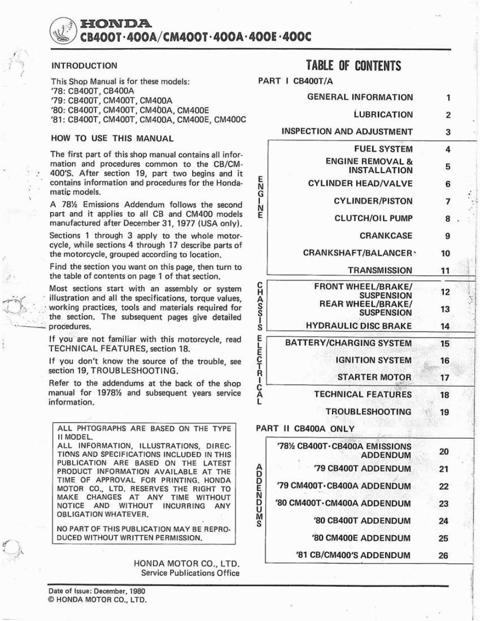
PART 11 @ HONDA CB400T MODEL lDEMTlFlCATlON TYPE I TYPE II i CB400T (I) BEGINNING FIN 2000001 CB400T (11) BEGINNING FIN 4000032 The frame serial number is stamped on the right side The legal vehicle identification number WIN) is on of the steering head. the left side of the steerins head. The engine serial number is stamped on the top of the crankcase. The carburetor identification number is on the left side of the carburetor body. Data of Issue: August, 1980 .O HONDA MOTOR CO., LTD.
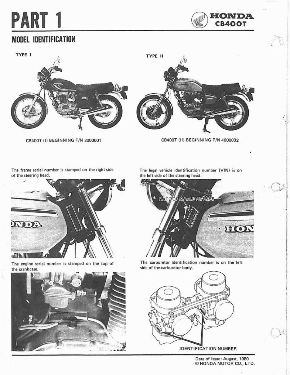
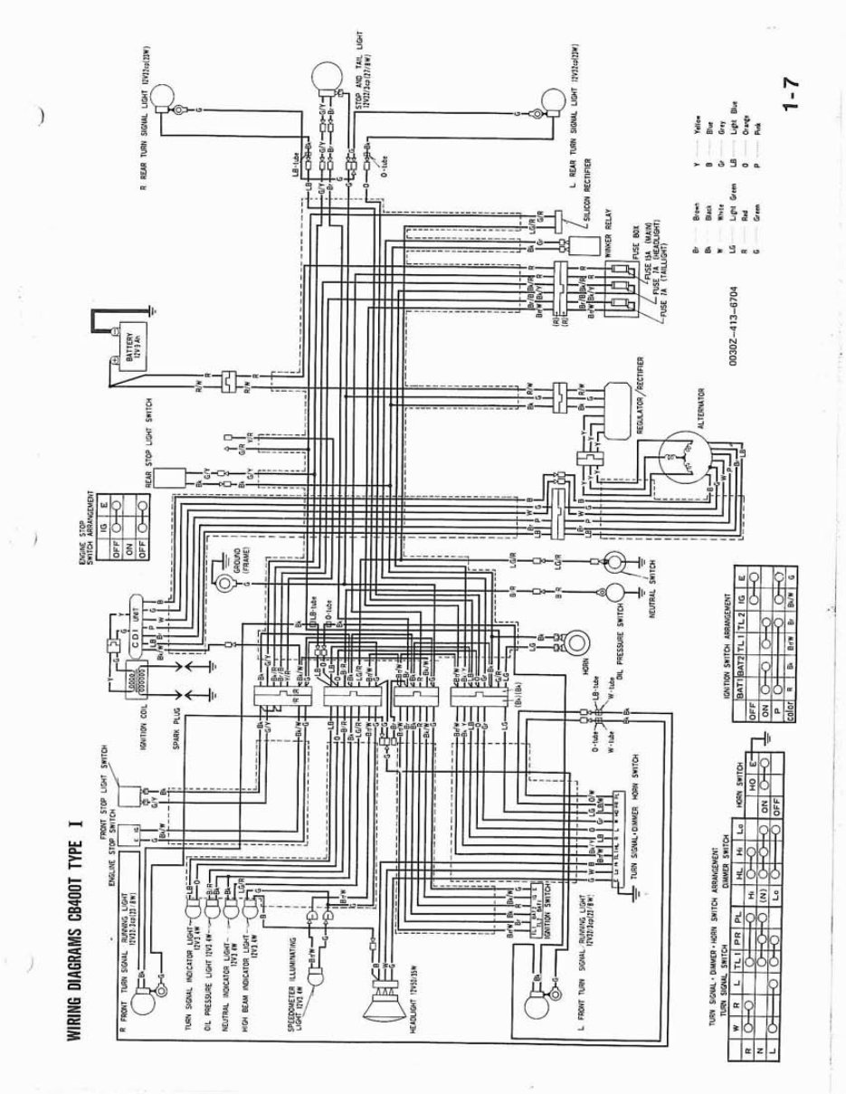
3 HONDA @ CB400T RAL INFORMATION GENERAL SAFETY 1-1 SPECIAL TOOLS 1-6 SERVICE RULES 1-1 WIRING DIAGRAMS 1-7 SPECIFICATIONS 1-2 CABLE & HARNESS ROUTING 1-9 TORQUE VALUES .I -4 MAINTENANCE SCHEDULE 1-12 ! GENERAL SAFETY If the engine must be running to do some work, make sure the area is well-ventilated, Never run the engine in a closed area. The exhaust containspoisonous carbon monoxide gas. Gasoline is extremely flammable and is explosive under certain conditions. Do not smoke or allow flames or sparks in your working area. 0 The battery electrolyte contains sulfuric acid. Protect your eyes, skin and clothing. In case of contact, flush thoroughly with water and call a doctor if your eyes were exposed. The battery generates hydrogen gas which can be highly explosive. Do not smoke or allow flames or sparks near the battery, especially while charging it. . SERVICE RULES 1. Use geniune HONDA or HONDA-recommended parts and lubricants or their equ~valent.Parts that do not meet HONDA's design specifications may damage the motorcycle. 2. Use the special tools designed for this product. 3, Install new gaskets, O-rings, cotter pins, lock plates, etc. when reassembling. 4. When torquing bolts or nuts, begin with larger-diameter or inner bolt first, and tighten to the specified torque diagonally, unless a particular sequence 1s specified. 5. Clean parts in cleaning solvent upon disassembly. Lubricate any sliding surfaces before reassembly. 6. After reassembly, check all parts for proper installation and operation. 7. Use only metric tools when servicing this motorcycle. Metric bolts, nuts, and screws are not interchangeable with English fasteners. The use of incorrect tools and fasteners may damage the motorcycle. Date of issue: September, 1977 O HONDA MOTOR CO., LTD. 1-1
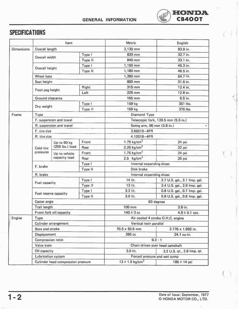
GENERAL INFORMATION ~. HONDA CB400T SPECIFICATIONS Date of Issue: September. 1977 O HONDA MOTOR CO.. LTD. Bore and stroke Displacement Compression ratio Valve train Oil capacity Lubrication system Cylinder head compression pressure 70.5 x 50.6 mm 2.776 x 1.992 in. 395 cc 24.1 cu-in. 9.3 : 1 Chain driven over head camshaft 3.0 lit. / 3.2 U.S. qt., 2.6 Imp. qt. Forced pressure and we1 13 * 1.0 kg/cm2 4 psi
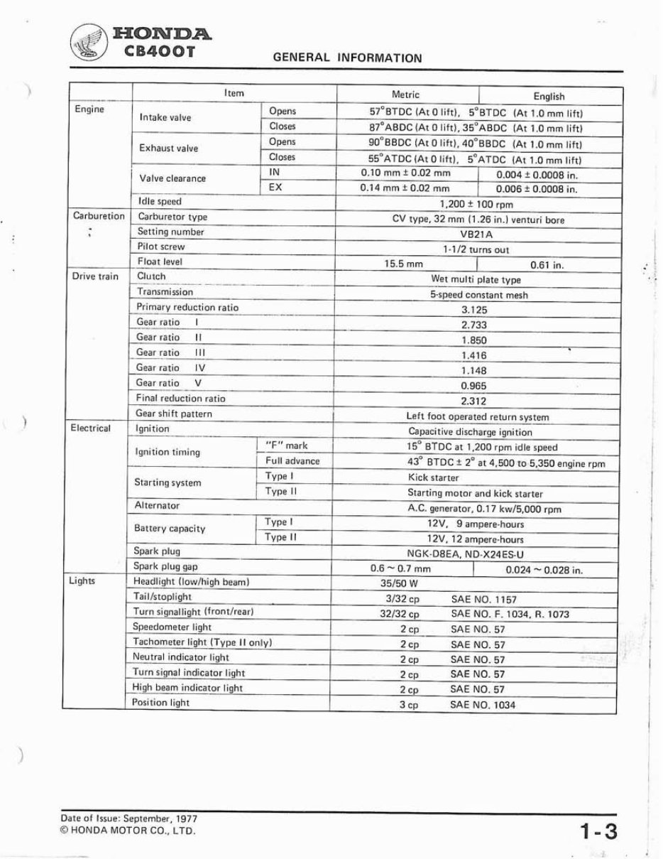
.. a HONDA GENERAL INFORMATION Date of Issue: September, 1977 0 HONDA MOTOR CO., LTD. 1-3
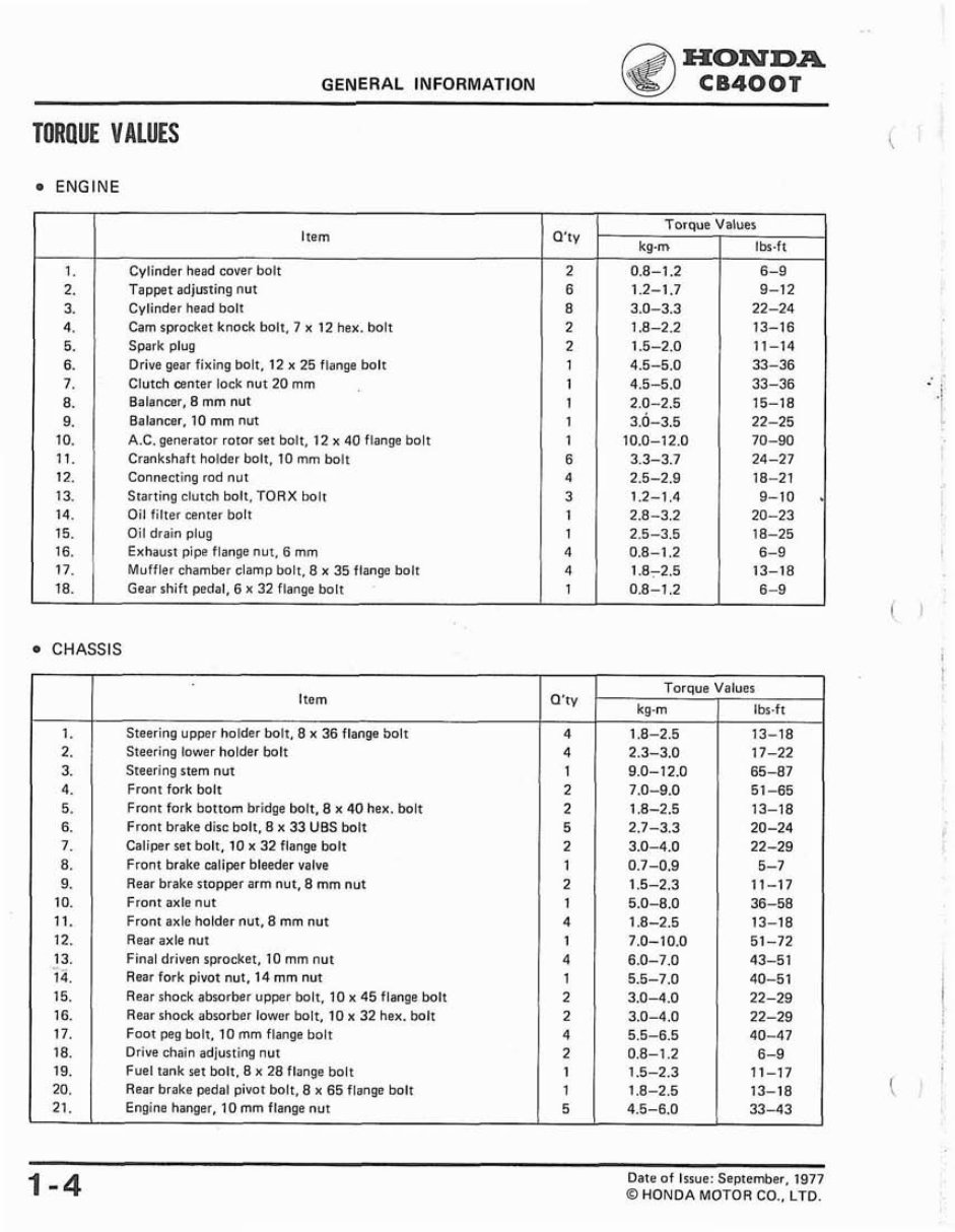
HONDA GENERAL INFORMATION CB400T TORQUE VALUES ENGINE CHASSIS 1. 2. 3. 4. 5. 6. 7. 8. 9. 10. 11. 12. 13. 14. 15. 16. 17. 18. - 1-4 Date of Issue: September, 1977 @ HONDA MOTOR CO.. LTD. Item Cylinder head cover bolt Tappet adjusting nut Cylinder head bolt Cam sprocket knock bolt, 7 x 12 hex. bolt Spark plug Drive gear fixing bolt, 12 x 25 flange bolt Clutch eenter lock nut 20 mm Balancer, 8 mm nut Balancer, 10 mm nut A.C. generator rotor set bolt, 12 x 40 flange bolt Crankshaft holder bolt, 10 mm bolt Connecting rod nut Starting clutch bolt, TORX bolt Oil filter center bolt Oil drain plug Exhaust pipe flange nut. 6 mm Muffler chamber clamp bolt, 8 x 35 flange bolt Gear shift pedal, 6 x 32 flange bolt 1. 2. 3. 4. 5. 6. 7. 8. 9. 10. 11. 12. 13. 14. 15. 16. 17. 18. 19. 20. 21. Q'ty 2 6 8 2 2 1 1 1 1 1 6 4 3 1 1 4 4 1 Item Steering upper holder bolt. 8 x 36 flange bolt Steering lower holder bolt Steering stem nut Front fork bolt Front fork bottom bridge bolt, 8 x 40 hex. bolt Front brake disc bolt, 8 x 33 UBS bolt Caliper set bolt, 10 x 32 flange bolt Front brake caliper bleeder valve Rear brake stopper arm nut, 8 mm nut Front axle nut Front axle holder nut. 8 mm nut Rear axle nut Final driven sprocket, 10 mm nut Rear fork pivot nut. 14 rnm nut Rear shock absorber upper bolt, 10 x 45 flange bolt Rear shock absorber lower bolt, 10 x 32 hex. bolt Foot peg bolt. 10 mm flange bolt Drive chain adjusting nut Fuel tank set bolt. 8 x 28 flange bolt Rear brake pedal pivot bolt, 8 x 65 flange bolt Engine hanger, 10 mm flange nut Torque kg-m 0.8-1.2 1.2-1.7 3.0-3.3 1.8-2.2 1.5-2.0 4.5-5.0 4.5-5.0 2.0-2.5 3.0-3.5 10.0-12.0 3.3-3.7 2.5-2.9 1.2-1.4 2.8-3.2 2.5-3.5 0.8-1.2 1.872.5 0.8-1.2 Q'ty 4 4 1 2 2 5 2 1 2 1 4 1 4 1 2 2 4 2 1 1 5 Torque kg-m 1.8-2.5 2.3-3.0 9.0-12.0 7.0-9.0 1.8-2.5 2.7-3.3 3.0-4.0 0.7-0.9 1.5-2.3 5.0-8.0 1 .8-2.5 7.0-10.0 6.0-7.0 5.5-7.0 3.0-4.0 3.0-4.0 5.5-6.5 0.8-1.2 1.5-2.3 1.8-2.5 4.5-6.0 Values Ibs-ft 6-9 9-12 22-24 13-16 11-14 33-36 33-36 15-18 22-25 70-90 24-27 18-21 9-10 . 20-23 18-25 6-9 13-18 6-9 Values Ibs.ft 13-18 17-22 65-87 51-65 13-18 20-24 22-29 5-7 11-17 36-58 13-18 51-72 43-51 40-51 22-29 22-29 40-47 6-9 11-17 13-18 33-43
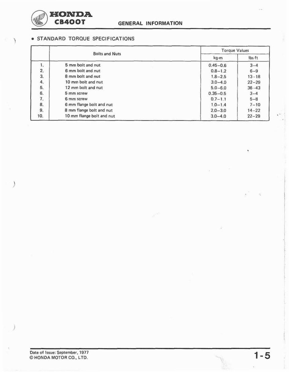
HONDA CB400T GENERAL INFORMATION \ a STANDARD TORQUE SPECIFICATIONS Date of Issue: September, 1977 O HONDA MOTOR CO., LTD. 1. 2. 3. 4. 5. 6. 7. 8. 9. 10. Bolts and Nuts 5 mm bolt and nut 6 mm bolt and nut 8 mm bolt and nut 10 mm bolt and nut 12 mm bolt and nut 5 mm screw 6 mm screw 6 mm flange bolt and nut 8 mm flange bolt and nut 10 mm flange bolt and nut - Torque Values kg-m 0.45-0.6 0.8-1.2 1 .8-2.5 3.0-4.0 5.0-6.0 0.35-0.5 0.7-1.1 1 .O-1.4 2.0-3.0 3.0-4.0 Ibs.ft 3-4 6-9 13-18 22-29 36--43 3-4 5-8 7-10 14-22 22-29 -
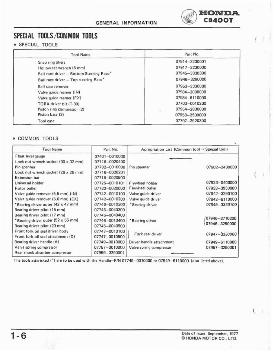
HONDA GENERAL INFORMATION CB400T SPEC1AL TOOLS /COM MON TOOLS SPECIAL TOOLS COMMON TOOLS Tool Name Snap ring pliers Hollow set wrench (6 mml Ball race driver - Bottom Steering Race* Ball race driver - T o p steering Race* Ball race remover Valve guide reamer (IN1 Valve guide reamer (EX1 TORX driver bit (T-30) Piston ring compressor (21 Piston base (2) Tool case I Tool Name I part NO. I Apropriation List (Common tool - Special tool1 1 Part No. 07914-3230001 07917-3230000 07945-3330300 07946-3290000 07953-3330000 07984-2000000 07984-61 10000 07703-001 0200 07954-2830000 07958-2500000 07797-2920300 Float level gauge Lock nut wrench socket (30 x 32 mml Pin spanner Lock nut wrench socket (26 x 29 mml Extension bar Universal holder Rotor puller Valve guide remover (5.5 rnml (IN1 Valve guide remover (6.6 mml (EX1 *Bearing driver outer (42 x 47 mml Bearing driver pilot (15 mm) Bearing driver pilot (17 mml "Bearing driver outer 152 x 55 rnm) Bearing driver pilot (20 mml t-- Pin spanner Flywheel holder Flywheel puller Valve guide driver Valve guide driver "Bearing driver 'Bearing driver Front fork oil seal driver body Front fork oil seal attachment (Dl 1 077470010100 } ,or, seal driver 07747-0010500 1-6 Date of Issue: September, 1977 0 HONDA MOTOR CO., LTD. Bearing driver handle (A1 Valve spring compressor Rear shock absorber compressor The tools asterisked ("I are to be used with the Handle-PIN 07749-0010000 or 07949-61 10000 (also listed above). 07749-0010000 07757-0010000 07959-3290001 Driver handle attachment 07949-61 10000 Valve spring compressor 07957-3290001 -
MyGreenManuals.com is your number one source for repair manuals. Our informative repair manual, owner's manuals, and parts catalogs contain all the information you'll need to perform repairs, look up parts, or do routine maintenance on your machine. You will have access to information regarding the following topics:
General Information
Routine Maintenance
Engine Removal and Installation
Fuel System
Lubrication and Cooling System
Engine Specifications
Transmission, Drive Chain & Sprockets
Steering System
Shocks
Body Work
Intake & Exhaust
Electrical System
Advanced Troubleshooting
With our repair manuals, find the page pertaining to your job, print it off, and get working on your machine. No more ruining your expensive paper shop manual with grease and dirt.
Broke down on the trail or site and have a smartphone? What a cool way to find your problem and repair it on the trail, no downtime on the job site. With our repair manuals, you instantly have access to the material needed to get you running again. Kind of tough to do that with a paper manual.
And did we mention the fact that you're saving the trees? All our repair manuals come with a lifetime protection policy. If lost or damaged, simply contact us and we'll replace it free of charge for life.
We provide various repair service manuals, workshop manuals, repair manuals, owners manuals, parts catalogs, and other various manuals, all in an electronic format.
UTVs, motorcycles, ATVs, quads, snowmobiles, Seadoo, equipment, small engines, inboards, outboards, and more.
Instant Access
No Shipping Cost
Get a Copy So No Waiting, Repair It Now
If you are looking for a specific manual and cannot find it or do not see it listed, then contact our customer support team via the contact us link above with details of the required manual and we will do our absolute best to find and list it for you. Instant access after payment. Thank you.