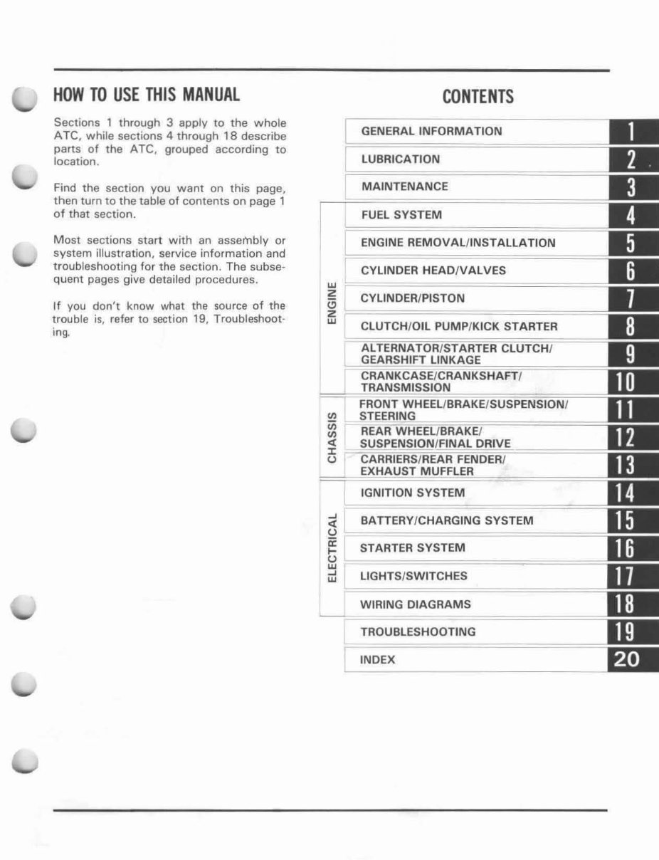
HOW TO USE THIS MANUAL Sections 1 through 3 apply [0 the whole ATe, white sections 4 through 18 describe parts of the ATC, grouped according to location, Find the section you want on this page, then turn to the table of contents on page 1 of that section. Most sections start with an assembly or system illustration, service information and troubleshooting for the section. The subse- quent pages give detailed procedures. If you don't know what the source of the trouble is. refer to section 19, Troubleshoot- ing. w Z to Z w -' <t u a: .... frl -' w CONTENTS GENERAL INFORMATION LUBRICATION MAINTENANCE FUEL SYSTEM ENGINE REMOVAL/INSTALLATION !rn INOER HEAO/V ALVES CYLINOER/PISTON CLUTCH/OIL PUMP/KICK STARTER IGNITION SYSTEM BATTERY/CHARGING SYSTEM STARTER SYSTEM LIGHTS/SWITCHES WIRING OIAGRAMS L-= ~============ TROUBLESHOOTING INDEX
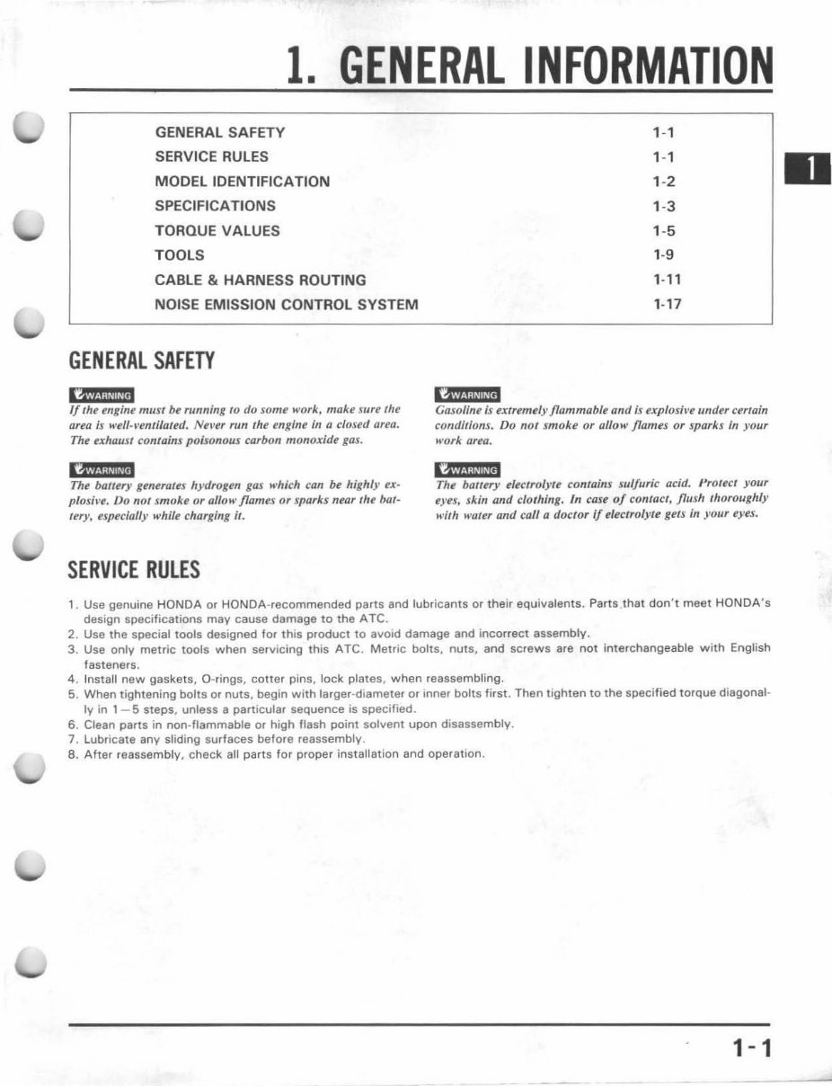
1. GENERAL INFORMATION GENERAL SAF ET Y SERVICE RU LES MODEL IDENTIFICATION SPECIFICATIONS TORQUE VALU ES TOOLS CABLE & HARNESS ROUTING NOISE EMISSION CONTROL SYSTEM GENERAL SAFETY l' f4W@i 1/ the engint' must be running to do som" work, make sure the Ufeu is ... efl-~'entilared. Never run t he engine in a closed QUO. The exhaust contains poi sonous carbon monoxide gas. GW.!;!.l!wa The bal/uy gtneralu hydrogen gas which can be highly ex- plash-e. Do nOl smoke or aliait' flames or sparks near the bat- tery, especially while charging It. SERVICE RULES ,-, ,-, ' -2 ' -3 ' -5 ' -9 ,- l' ,- 17 "'"-"""' /s. ;X"","'''/) /lammable and is f'XpfosiI'f! under certain conditions. Do not smoke or allow flames or sparks in )'our work area. The baltery electfolyu contains sui/uric acid. {',otect )' OU1 eyes, skin and clo/hing. In case 0/ contact, /lush ,horollghly wilh water and call a doctor if electrol yte gelS in your eyes. , . Use genuine HONDA or HONDA-recommended parts and lubricants or their equivalents. Parts.that don 't meet HONDA's design specifications may cause damage to the ATC. 2. Use the special tools designed for this product to avoid damage and incorrect assembly. 3. Use only metric tools when servicing this ATC. Metric bolts, nuts, and screws are not interchangeable with English fastener s. 4 . Install new gaskets, O-rings, cotter pins, lock plates, when reassembling. 5. When tightening bolts or nuts , begin with larger-diameter or inner bolts first. Then tighten to the specified torque diagonal- ly in 1 - 5 steps, unless a particular sequence is specified. 6. Clean parts in non-flammable or high flash point solvent upon disassembly. 7. Lubricate any sliding surfaces before reassembly. 8. After reassembly, check all parts for proper installation and operation. 1-1
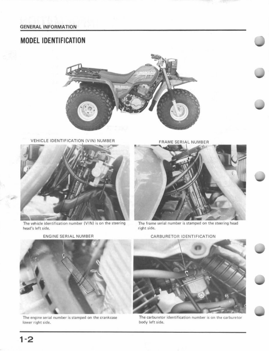
GENERAL INFORMATION MODEL IDENTIFICATION VEH ICLE IIDENTIFICATICIN head's left side. ENGINE SERIAL NUMBER The engine serial number is stamped on the crankcase lower right side. 1-2 The frame serial number is stamped on the steering head right side. CARBURETOR IDENTIFICATION The carburetor identification number is on the carburetor body left side.
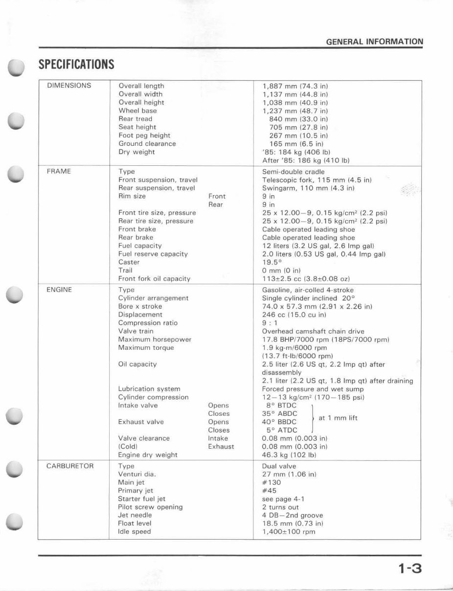
SPECIFICATIONS DIMENSIONS FRAME ENGINE CARBURETOR Overall length Overall width Overall height Wheel base Rear tread Seat height Foot peg h eight Ground clearance Dry weight Type Front suspension, travel Rear suspension, travel Rim size Front tire size, pressure Rear lire size, pressure Front brake Rear brake Fuel capacity Fuel reserve capacity Caster Trail Front fork oil capacity Type Cylinder arrangement Bore x stroke Displacement Compression ratio Valve train Maximum horsepower Maximum torque Oi l capacity Lubrication system Cylinder compression Intake valve Exhaust valve Valve clearance (Cold) Engine dry weight Type Venturi dia. Main jet Primary jet Starter fuel jet Pi lo t screw opening Jet needle Float level Idle speed Front Rear Opens Closes Opens Closes Intake Exhaust GENERAL INFORMATION 1,887 mm 174.3 in) 1,137 mm ( 44.8 in) 1,038 mm (40.9 in) 1,237 mm \48.7 in) 840 mm (33.0 in) 705 mm 127.8 in) 267 mm (lO.S in) 165 mm (6 .5 in) '85 : 184 kg (406 Ibl A ft er '85: 186 kg (41 0 Ib) Semi-doub le cradle Te l escopic fork, 115 mm 1 4.5 in) Swingarm, 110 mm (4.3 in) 9 in 9 in 25 x 12.00 - 9,0.15 kg / cm 2 (2.2 psi) 25 x 12.00-9 , 0.15 kg / cm 2 12.2 psi) Cable operated leading shoe Cable operated leading shoe 12 liters (3.2 US ga l, 2.6 Imp gal) 2.0 liters (0.53 US gal, 0.44 Imp gal) 19.5 ° o mm (0 in) 113+2.5 cc (3.8+0.08 oz) Gasoline, air- coiled 4 -s troke Single cy l inder inclined 20° 74.0 x 57 .3 mm 12 .91 x 2.26 in) 246 cc ( 15 .0 cu in) 9 1 Overhead camshaft chain drive 17.8 BH P!7000 rpm (18PS!7000 rpm) 1.9 kg-m / 6000 rpm (1 3.7 ft - lb/ 6000 rpm) 2.5 l iter (2 .6 US qt, 2.2 Imp qtl after disassembly 2.1 liter (2.2 US qt, 1.8 Imp qtl after draining Forced pressure and wet sump 12 - 13 kg/ cm 2 ( 170 - 185 psi) 8° BTDC 35° ABDC 40 ° BBDe 5° ATDC 0.08 mm (0.003 in) 0.08 mm (0.003 in) 46.3 kg ( 102 Ib ) Dual valve 27 mm n .06 in) #130 #45 see page 4-' 2 turns out 4 DB - 2nd groove 18.5 mm (0.73 in) 1 ,400± 1 00 rpm mm lift 1-3
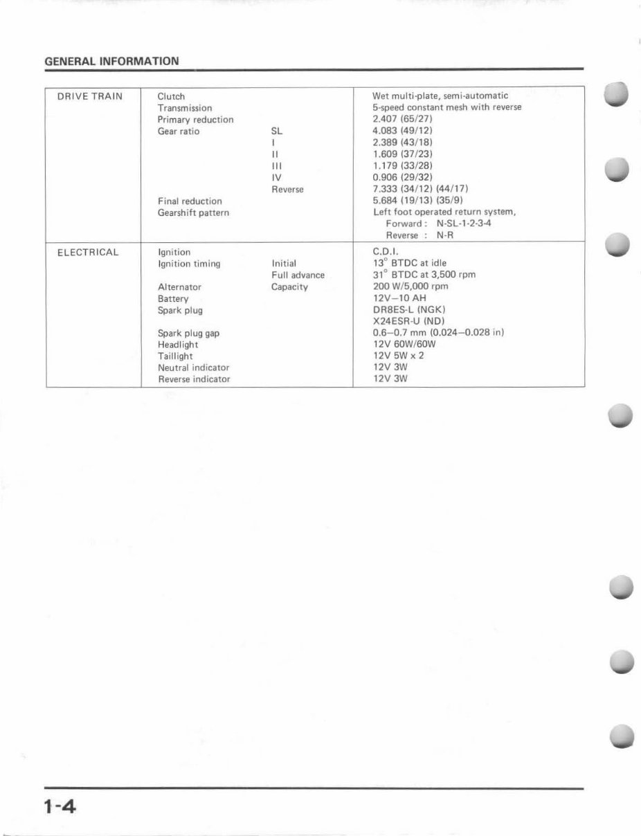
GENERAL INFORMATION DRIVE TRAIN Clutch Wet multi·plate, semi · automatic Transm ission 5-speed constant mesh wi th reverse Primary reduction 2.407 (65/27) Gear rat io SL 4.083 (49/ 12) , 2.389 (43/18) II 1.609 (37/23) "' 1.179 (33/28) ,v 0.906 (29/32) Reverse 7.333 (34/12) (44/ 17 ) Final reduction 5.684 (19 / 13) (35 /9) Gearshift pattern left foot operated return system, Forward: N·$L·,·2 ·3-4 Reverse N-R ELE CTRICAL Ignition C.D.I. Ignition timing Init ial 13 0 BTDC at idle Full advance 31 0 BTDe at 3,500 rpm Alternator Capacity 200 W/ 5,OOO rpm Battery 12V- 10 AH Spark plug OA8ES-L (NGK) X24ESR-U (NO) Spark plug gap 0.6- 0.7 mm (0,024-0.028 in) Headlight 12V SOW/BOW Taillight 12V5Wx2 Neutral indicator 12V 3W Reverse indicator 12V 3W 1-4
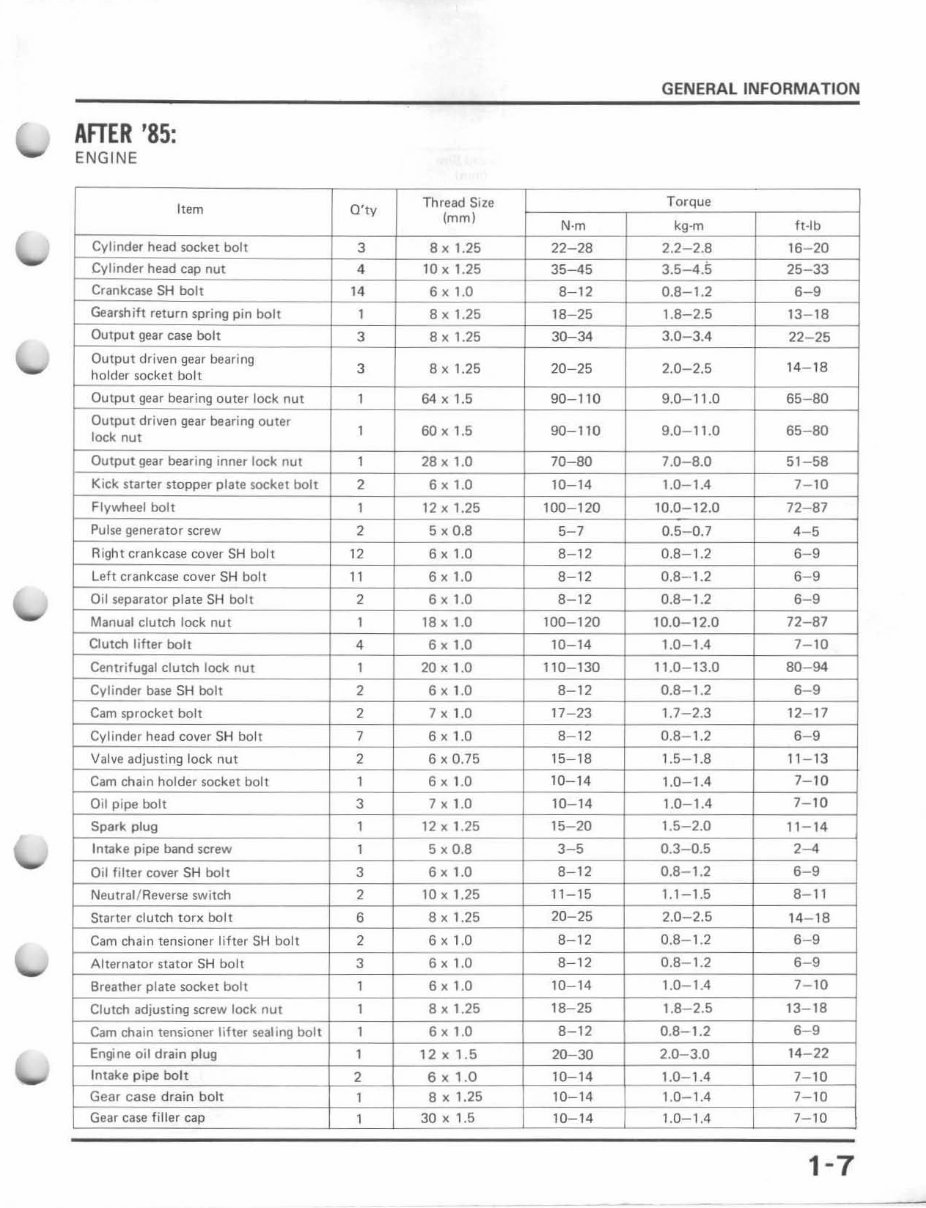
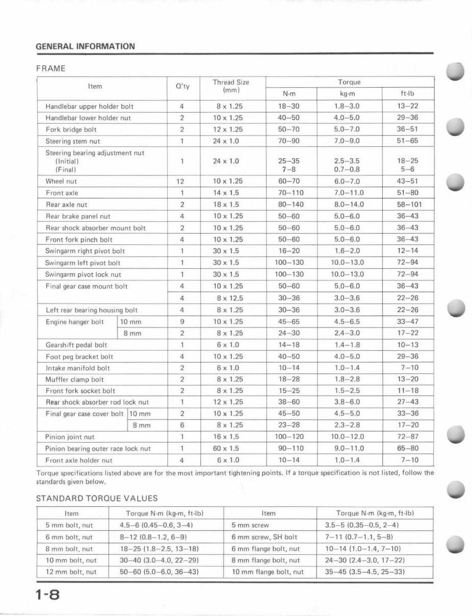
Get access to top-quality professional workshop service and repair manuals, essential for both professional mechanics and DIY enthusiasts. These manuals provide detailed instructions and step-by-step diagrams for all workshop procedures, including but not limited to changing plugs, rebuilding engines, electrical diagrams, torque settings, and fluid capacities.
With just a click, you can access comprehensive diagnostic, service, repair, and maintenance information, as used by professional technicians and mechanics. These manuals, written by manufacturers, contain thousands of pages of diagrams and detailed information for specific vehicle or equipment repair, making them the most accurate and complete source of original service manuals, wiring diagrams, and bulletins.
Each service repair workshop manual is year and model specific, featuring factory diagnostic and repair procedures, providing access to the same repair information used by certified technicians and mechanics. The manuals are available in easy-to-use Acrobat PDF files and are compatible with both Windows and MAC operating systems.
Accepting all forms of payment including Paypal, Credit, and Debit Cards, these manuals are a valuable resource for anyone in need of reliable and detailed repair information.
Reviews
Q&A
Recently Viewed
5,521,897Happy Clients
2,594,462eManuals
1,120,453Trusted Sellers
15Years in Business
Price:
Actual Price:
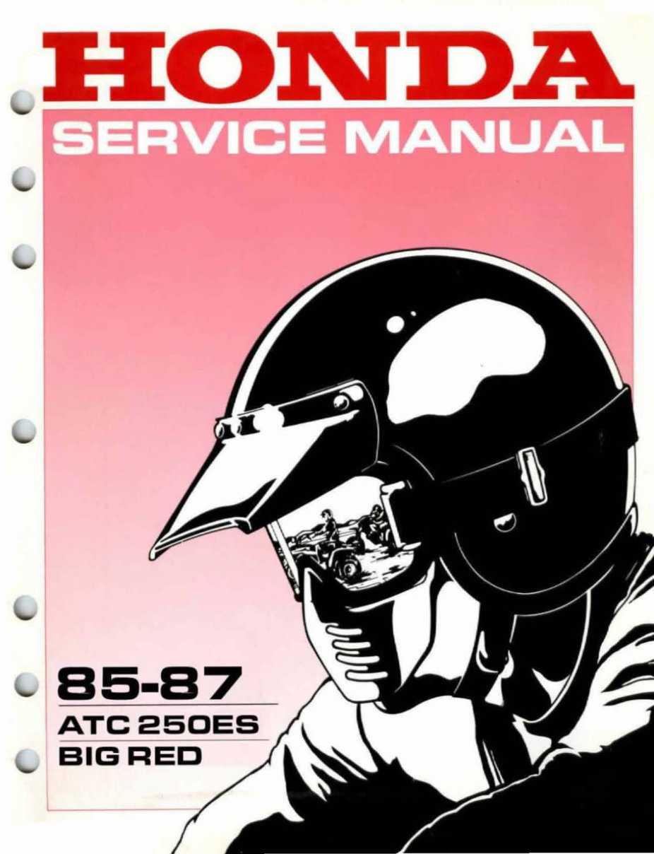
HONDA ATC 250ES BIG RED Workshop Repair Manual 1985




 Lifetime Access




