'#'1,@ii!ij Indicates a strong possibility of severe personal injury or loss of life if instructions are not followed. CAUTION: Indicat es a possibility of personal injury or e quipm ellt damage if i ns trtl C- lions are not followed. NOTE: Gives helpful information. Detailed descriptions of standard workshop procedures, safety principles and service operations are not included. It is important to note that this manual contains some warnings and caut ions against some specific service methods which cou ld cause. PERSONA L INJURY to service personnel or could damage a vehicle or render it unsafe. Please understand that those warnings could not cover all conceivable ways in which service, whether or not recommended by Honda might be done or of the possible hazardous consequences of each conceivable way, nor could Honda investigate all such ways . Anyone using service procedures or tools, whether or not rcommended by Honda must satisfy himself thoroughly that neither personal safety nor vehicle safety will be jeopardized by the service methods or tools selected.
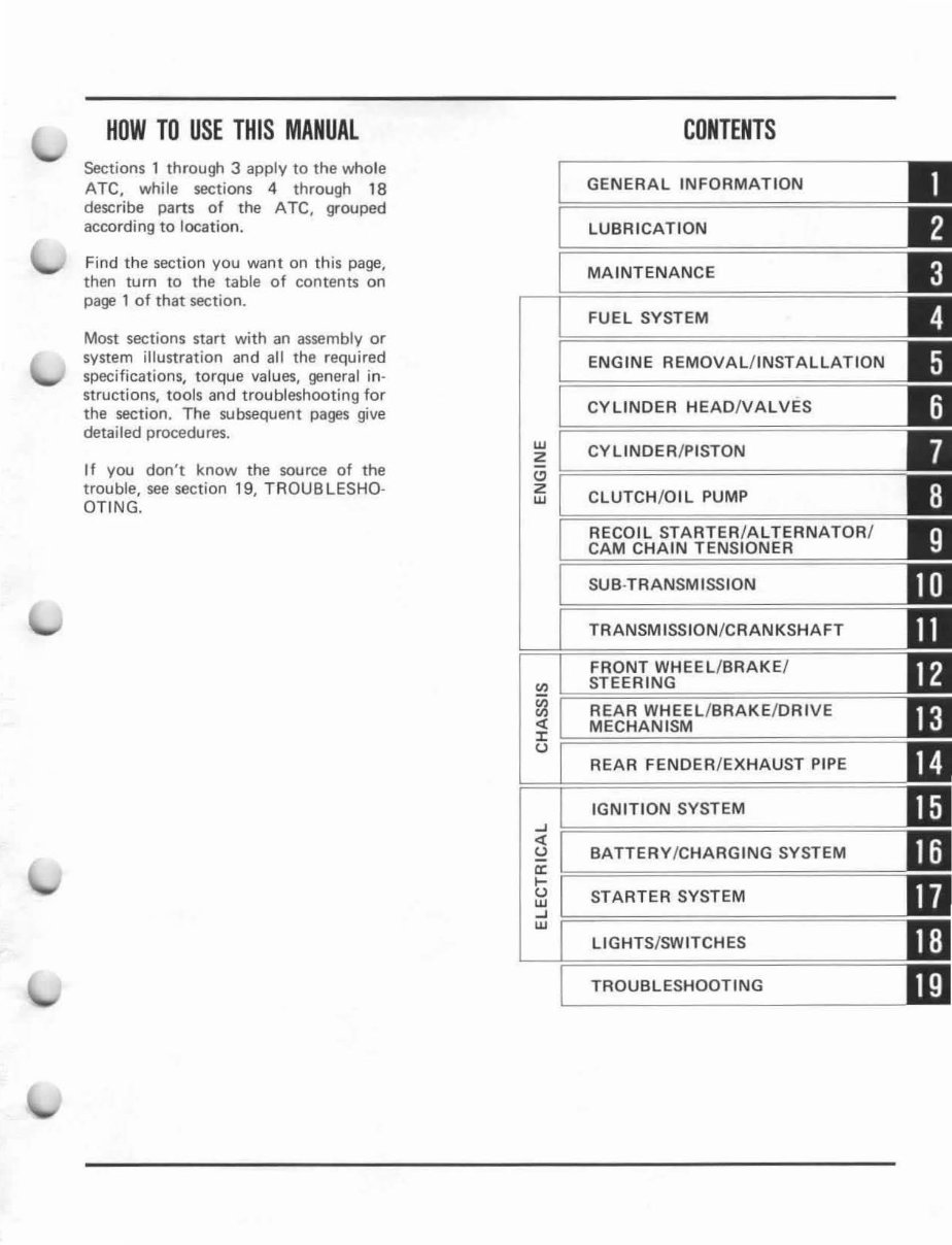
HOW TO USE THIS MANUAL Sections 1 through 3 apply to the whole ATe. whi le sections 4 through 18 describe pa rts of the ATe. grouped accordi ng to loca tion. Find the sect i on you want on this page, then turn to the table of contents on page 1 of that section. Most sections start wi th an assemb ly or system illustration and al l the req uired specifi ca ti ons, torque va lu es, gene ral in- st ru ctions, tools and troubleshooting for the section. The subsequent pages give detailed procedures. I f you don't know th e source of the trouble, see sec tion 19, T ROU B LESHO· OTI NG. w Z " Z w CONTENTS GENERAL INFORMATION LUBR ICA TlON MAINTENANCE FUEL SYSTEM ENGINE REMOVAL / INSTALLATION CYLINOER HEAOIVALVES CYLINOER/PISTON CLUTCH/ OIL PUMP RECOIL STARTER/ ALTERNATOR / CAM CHAIN TENSIONER SUB · TRAN SMISSION TRANSMISSION / CRANKSHAFT WHEEL/BRAKE/ ~ REAR WHEEL / BRAKE /ORIVE ~ MECHANISM (J ...J .. (J a: t; w ...J W REAR FENOER/EXHAUST PIPE IGNITION SYSTEM BATTERY/CHARGING SYSTEM ST ARTER SYSTEM LIGHTS/SWITCHES TROUBLESHOOTING
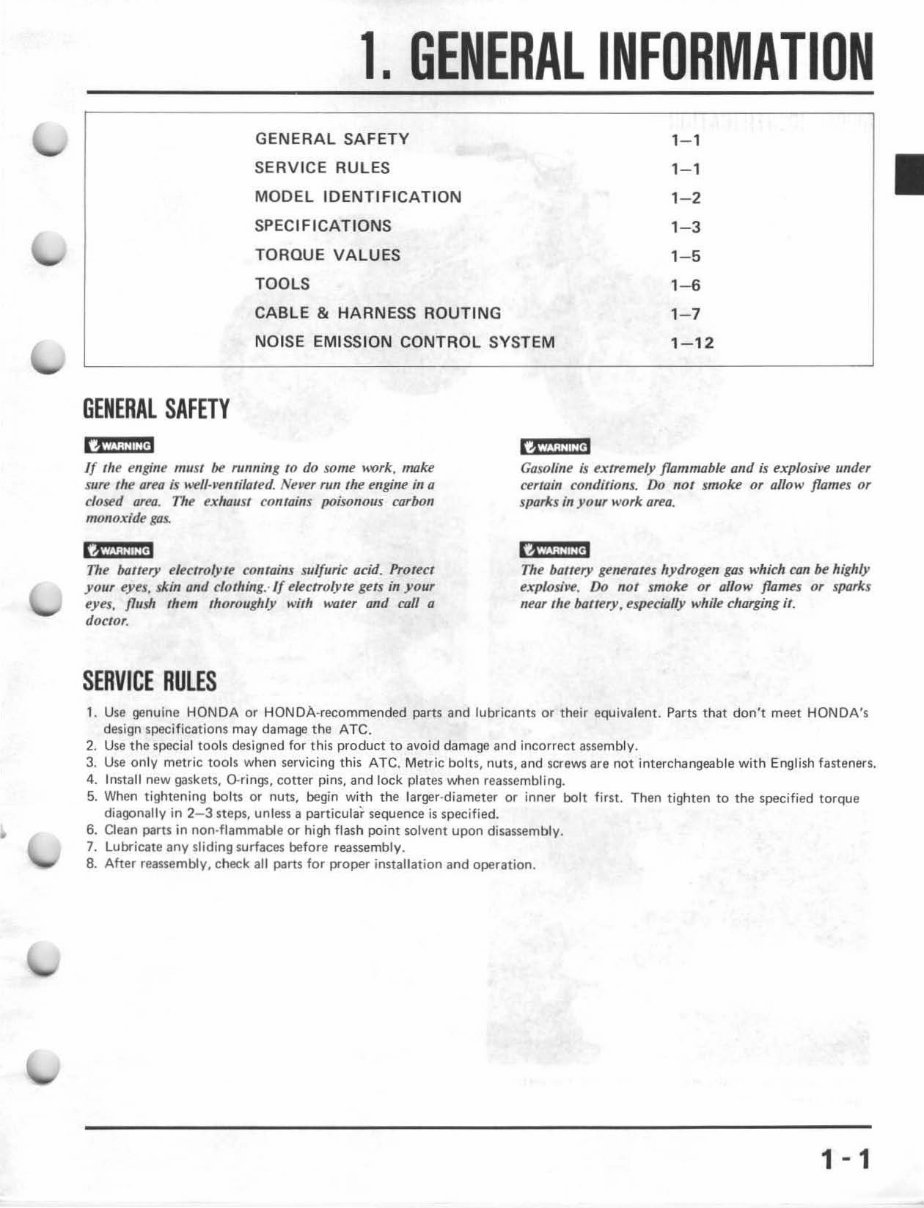
• 1. GENERAL INFORMATION GENERAL SAFETY 1- 1 SERVICE RULES 1- 1 MODEL IDENTIFIC AT ION 1-2 SPECIFICATIONS 1-3 TOROUE VALUES 1- 5 TOOLS 1- 6 CABLE & HARNESS ROUTING 1- 7 NOISE EMISSION CONTROL SYSTEM 1- 12 GENERAL SAFETY 13 i ';iiil,jfj If the engine must be running 10 do some work, miJke sure the area ;$ well-J'enliloted. NeJoer run fhe engine in a closed area. Th e exhaust contains poisonous carbon monoxide gas. 14 "ji:U:!.i 7111.' baltery eleclrolYlf.' contains sulfun "c add, Protect your eyes, skin and clothing., If t!lect7olyte gelS in your eyes, flush them th oroughly with water and call 0 dOClor. SERVICE RULES 14/i;1:i@' Gasoline ;s extremely flammable Qnd is exp/oshV! und er certo;n conditions. 00 not smoke or allow /lames or sparks in your work area. ,,,,'ii / 3 M3 The boffery le~raus hydrogen gas which can be highly f.'xp/osh't!. Do not smoke or allow flames or sparks neor the bauery. t'speciolly while charging iI. 1, Use ge nuine HONDA or HONDA-recommended parts and lubricants or their equivalent. Parts that don't meet HONDA's design specifications may damage the ATC. 2. Use the special tools des ign ed for this product to avoid damage and incorrect assembly. 3. Use only metric tools when se rv icing thi s ATC. Metric bol t s, nuts, and screws are not interchangeable with English fasteners. 4. Install new gaskets, O-ri ngs, cotter pins, and lock plates when reassembling. 5. When tightening oolts or nuts, begin wi th the la rger·diameter or inner bolt first. Then tighten to the specified torque diagonally in 2-3 steps, unless a particular sequence is specified. 6. Clean parts in non-flammable or high flash point solvent upon disassembly . 7. Lubricate any sliding su rfaces before reassembly. 8. After reassembly, check all parts for proper installation and operation. 1 - 1
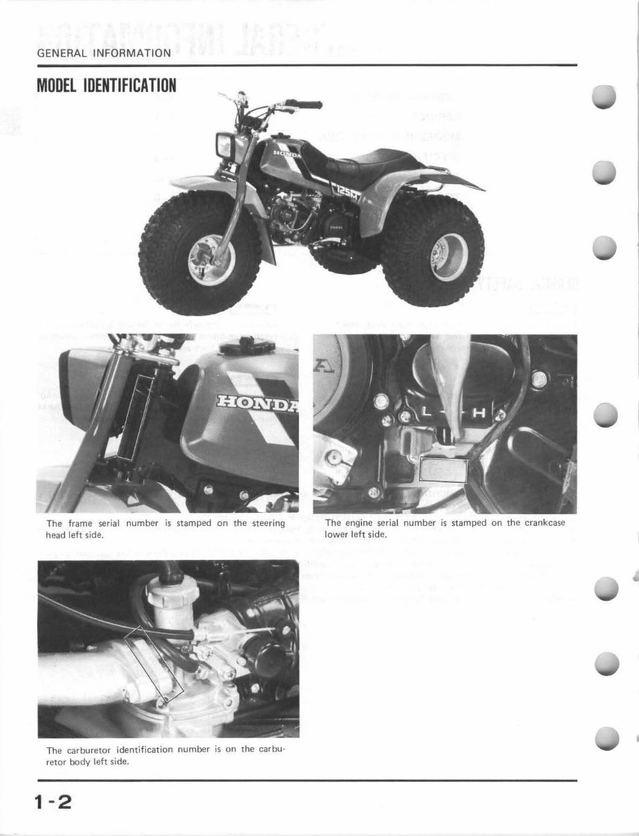
GENERAL INFORM ATION MODEL IDENTIFICATIDN The frame serial number is stamped on the steering head left side. The carburetor identification number is on the carbu- retor body left side. 1 -2 The engine serial number is st amped on the crankcase lower left side.
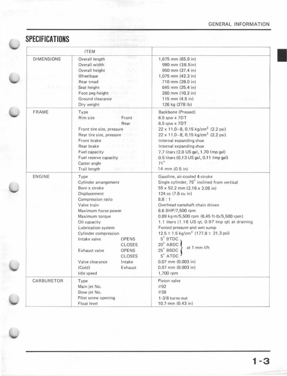
GENERAL INFORMATION SPECIFICATIONS ITEM DIMENSIONS Overall length 1,675 mm (65.9 in) Overall width 980 mm (38.Sin) Overall h eight 950 mm (37.4 in) Wheelbase 1,075 mm (42.3 in) Rear tread 7 10 mm (28.0 in) Seat height 645 mm (25.4 in) Foot peg height 260 mm (10.2 in) Ground clearance 115 mm (4.5 in) Dry weight 126 kg (278 fb) FRAME Type Backbone (pressed) Rim size Fron t 6.5 SPW)( lO T Rear 6.5 spw x 70T Front tire size, pressure 22 x 11.0- 8,0.15 kg/cm' (2.2 psi) Rear tire size, pressure 22)( 11.0- 8,0,15 kg/ em' (2.2 psi) Front brake Internal expa nd ing shoe Rear brake Internal expa nding shoe Fuel capacity 7.7 liters (2.0 US gal, 1.70 Imp gal) Fuel reserve capacity a.Sliters (0. 13 US gal, 0. 11 Imp gall Caster angle ,," Trail length 14 mm (0.5 in) ENGINE Type Gasoline, air-cooled 4-stroke Cylinder arrangement Single cylinder, 75° inclined fr om vertical Bore x stroke 55 x 52.2 mm (2.16)( 2.05 in) Displacement 124 cc (7.6 cu in) Compression ratio 8.8; 1 Valve train Overhead ca mshaft chain driven Maximum horse power 8.6 8HPI7,500 rpm Maximum torque 0.89 kg-m/ 5,SOO rpm (6.45 ft -lb/S,500 rpm) Oil capacity 1.1 liters (1.16 US qt , 0 .97 Imp qt) at draining Lubrication system Forced pressure and wet sump Cylinder compression 12.5 ± 1. 5 kg/cm 1 (177.8 ± 21.3 psi) Intake valve OPENS 5° BTDC CLOSES 20" ABDC } at 1 mm lift Exhau st va lve OPENS 25° BBDC CLOSES SO ATDC Valve cl ea ra nce Intak e 0.07 mm (0.003 in) (Cold) Exhaust 0.07 mm (0.003 in) Idle speed 1,700 r pm CARBURETOR Ty", Piston valve Main jet No. .tf 92 Slow jet No. .:;38 Pilot screw opening 1-3/8 turns out Float level 10.7 mm (0.43 in) 1-3
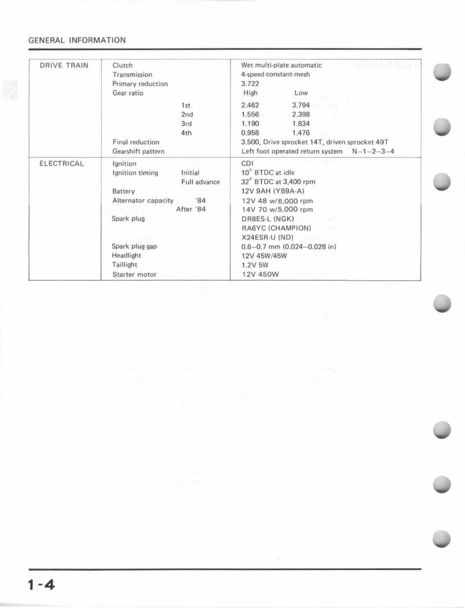
GENERAL INFORMATION DRIVE TRAIN Clutch Wet multi-plate automatic Transmission 4·speed constant-mesh Primary reduction 3.722 Gear ratio High Low ,,, 2.462 3.794 2nd 1.556 2.398 3,d 1.190 1.834 4th 0.958 1.476 Final reduction 3.500, Drive sprocket 14T, driven sprocket 49T Gearshift pattern left foot operated return system N- 1-2-3-4 ELECTRICAL Ignition COl Ignition timing In itial 10° BTDC at idle Full ad ... ance 32° BTDC at 3,400 rpm Battery 12V 9AH (YS9A·A) Alternator capacity '84 12V 48 w/6,OOO rpm After '84 14V 70 wf5,OOO rpm Spark plug DA8ES-L (NGK) RA6YC (CHAMPION) X24ESR-U (NO) Spark plug gap 0.6-0.7 mm (0.024 - 0.028 in) Headlight 12V 45W!45W Taillight 1.2V 5W Starter motOf 12V 450W 1-4
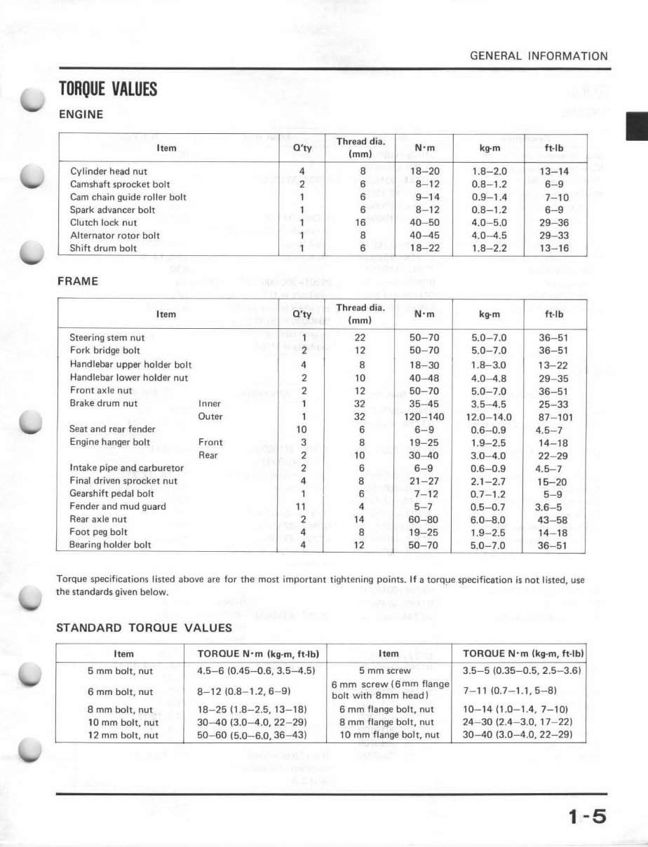
GENER AL INFORMATI ON TORQUE VALUES ENGINE Item Q 'ty Thread di a. N'm k~m ft-Ib (mm ) Cylinder head nut • 8 18- 20 1.8- 2.0 13- 14 Camshaft sprocket bolt 2 6 8- 12 0.8-1.2 6- " Cam chain guide roller bolt 1 6 9- 14 0.9- 1.4 7-10 Spark advancer bolt 1 6 8- 12 0.8- 1.2 6- " Clutch lock nut 1 16 40- 50 4.0-5.0 2"- 36 Alternator rotor bolt 1 8 40-45 4.0 - 4.5 29- 33 Shift drum bolt 1 6 18-22 1. 8- 2.2 13- 16 FRAME It em O'W Th read dis. (mm ) N' m k~ m ft·l b Steering stem nut 1 22 50 - 70 5.0-7.0 36- 51 Fork bridge bolt 2 12 50 - 70 5.0- 7.0 36 - 51 Handlebar upper holder bolt • 8 18-30 1.8-3.0 13-22 Handlebar l ower holder nut 2 10 40-48 4.0- 4.8 29- 35 Front axle nut 2 12 50 - 70 5.0- 7.0 36 - 51 Brake drum nut Inner 1 32 35 - 45 3.5- 4.5 25- 33 Outer 1 32 120- 140 12.0- 14.0 87 -101 Seat and rear fender 10 6 6- " 0.6- 0.9 4.5-7 Engine hanger bolt Front 3 B 19-25 1. 9- 2.5 14- 18 Rear 2 10 30-40 3.0 - 4.0 22- 29 Intake pipe and carburetor 2 6 6- " 0.6- 0.9 4.5-7 Final driven sprocket nut • B 21 - 27 2. 1-2.7 15-20 Gearshift pedal bolt 1 6 7- 12 0.7- 1. 2 5-" Fender and mud guard 11 • 5- 7 0.5-0.7 3.6 -5 Rear axle nut 2 " 60-80 6. 0- B.O 43 - 58 Foot peg bolt • B 19- 25 1.9-2.5 14- 18 Bearing holder bolt • 12 50 70 5.0 7.0 36 51 Torque specifications listed above are for the most important tightening points. If a torq!le specification is not listed, use the standards given below. STANDARD TORQUE VALUES Item TORQUE Nom !kg -m, ft·lb) Item TORQUE N·m !kg-m, ft -IM 5 mm bolt, nut 4.5- 6 (0.45- 0.6, 3.5-4.5) 5 mm screw 3.5- 5 (0.35- 0_5 , 2.5- 3.6) 6 mm bolt , nut 8-12 (0.8- 1.2, 6- 9) 6 mm screw (6mm flange 7- 11 (0.7- 1.1,5-8) bolt with 8mm head) 8 mm bolt, nut 1B- 25 ( 1. 8- 2_5, 13- 18) 6 mm flange bolt, nut 10-14 (1.0- 1.4 , 7- 10) 10 mm bolt, nut 30 - 40 (3.0- 4.0, 22- 29) 8 mm flange bolt, nut 24 - 30 (2.4- 3.0, 17- 22) 12 mm bolt, nut 50- 60 (5_0-6.0,36-43) 10 mm flange bol t , nut 30 - 40 (3.0- 4.0, 22- 29) 1 -5
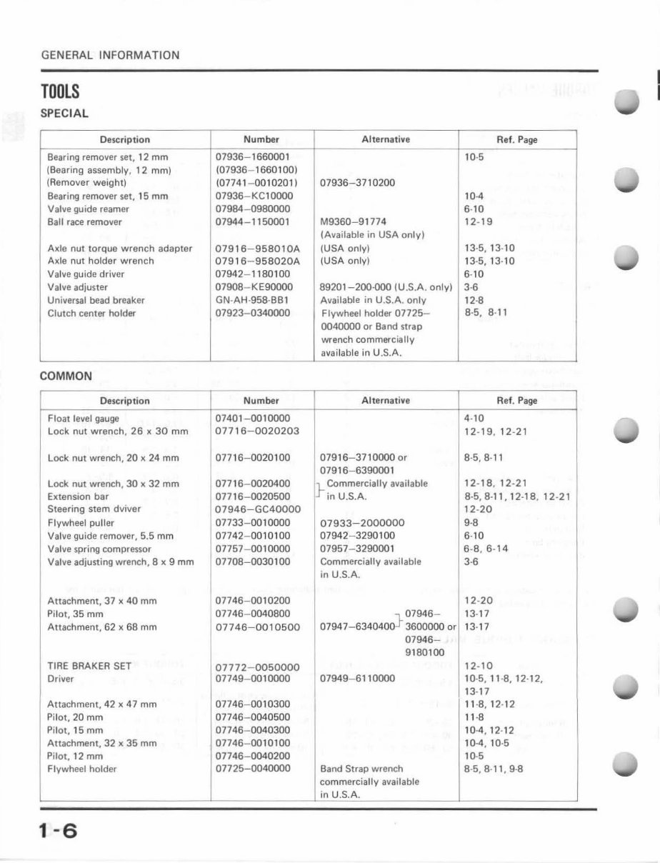
GE NERAL INFORMATION TOOLS SPEC I AL Description Number Beari ng remover set, 12 mm 07936- 1660001 (Bearing assembly. 12 mm) (07936- 1660100) (Remover weight) (0774 1- 0010 201 ) Bearing remover set, 15 mm 07936 - KC10000 Valve guide reamer 07984- 0980000 Ball race remover 07944 - 1150001 Axle nut torque wrench adapter 07916 - 958010A Axle nut ho lder wrench 07916 - 958020A Va lve guide driver 07942- 1180100 Valve adjuster 0790B- KE90000 Universal bead breaker GN - AH - 958-BBl Clutch center holder 07923- 0340000 COMMON Description Number Float level gauge 07401 - 00 10000 Lock nut wrench, 26 x 30 mm 07716 - 0020203 Lock nut wrench, 20 x 24 mm 07716- 0020100 Lock nut wrench, 30 x 32 mm 077 16- 0020400 Extension bar 07716- 0020500 Steering stem dviver 07946 - GC40000 Flywheel puller 07733- 0010000 Valve guide remover, 5.5 mm 07742- 0010100 Valve spring compressor 07757- 0010000 Valve adjusting wrench, 8 x 9 mm 07708- 0030100 Attachment, 37 x 40 mm 07746-00 10200 Pi lot, 35 mm 07746- 0040800 Attachment, 62 x 68 mm 07746-0010500 TIRE BRAKER SET 07772 - 0050000 Driver 07749- 0010000 Attachment, 42 x 47 mm 07746- 00 10300 Pilot, 20 mm 07746- 0040500 Pilot, 15 mm 07746- 0040300 Attachment, 32 x 35 mm 07746- 0010100 Pilot, 12 mm 07746- 0040200 Flywheel holder 07725- 0040000 1-6 Alternative 07936 - 3710200 M9360- 91774 (Available in USA only) (USA only) (USA only) 89201 - 200-000 (U .S.A . only) Available in U.S.A. only Flywheel holder 07725- 0040000 or Band strap wrench commercially available in U.S.A. Alternative 079 16- 3710000 or 079 16- 6390001 Commercially available r- in U.S.A 07933 - 2000000 07942- 3290 1 00 07957- 3290001 Commercially available in U.S.A , 07946- 07947- 6340400} 3600000 or 07946 - 9180 100 07949- 6110000 Band Strap wrench commercially available in U.S.A. Ref. Page 10·5 10-4 6-10 12· 19 13·5, 13-10 13·5,13-10 6-10 3 -6 12-8 8·5, 8-11 Ref. Page 4·10 12- 19, 12-21 8·5,8 · 11 12- 18 , 12-21 8·5,8 ·11, 12-18, 12-21 12-20 9-8 6·10 6-8, 6- 14 3 -6 12-20 13·17 13·17 12- 10 10-5, 11 -8, 12·12, 13·17 11 - 8,12 · 12 11·8 10·4,12 -12 10-4, 10-5 10-5 B·5, B-l1 , 9-8 I I I I
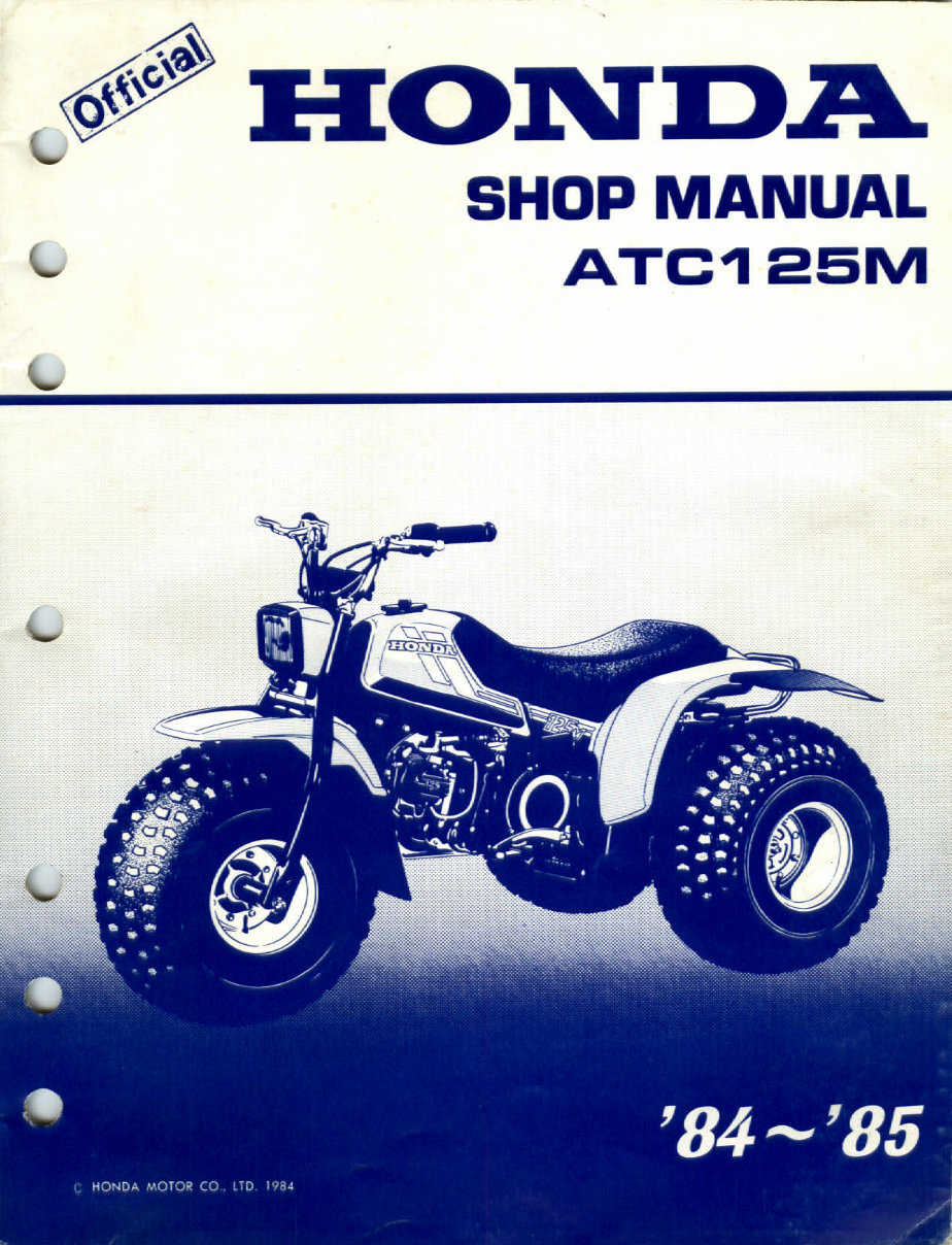
The ATC125M Honda Repair Service Manual covers the years 1984 and 1985. It is a valuable resource for both professional mechanics and DIY enthusiasts. This manual provides detailed illustrations and step-by-step instructions for various repairs, including general information, engine service and overhauling, transmission, chassis, body, wiring, fuel system, emission control, induction, mechanical, control system, troubleshooting and diagnostics, steering and suspension, brakes, ABS, full specifications and torque settings, service work, and more.
Every detail related to repairs, from fixing lights to building transmission, is comprehensively covered. The manual is printable, allowing easy access to the required information in the garage or workshop. It is specifically written for individuals with basic mechanical skills and experienced mechanics, offering a cost-effective way to maintain vehicles.
Each manual provides step-by-step instructions based on complete machine disassembly, accompanied by numerous photos and illustrations to guide the reader through each service and repair procedure. The manual is available in PDF format, compatible with PC-based Windows operating systems, Mac, and various devices including phones and e-readers like the Amazon Kindle.
Topics covered in the manual include general maintenance, troubleshooting, engine service/repair, transmission service/repair, brake system, electrical system, suspension, wiring diagram, periodic lubrication, steering, cooling system, fuel injection/fuel system, emission system, heater/air conditioning, engine control system, chassis/body, restraint system, interior, differential/drive, axle, and more.
Upon payment completion, the manual is instantly accessible without any shipping costs or waiting for a CD. For any inquiries, please feel free to contact us. Your satisfaction is guaranteed.