

IMPORTANT SAFETY NOTICE
tl:t.I;I'IliM Indicates a strong possibility oj se l'ere personal injury or loss of life if instructions ore not /o llo14·ed.
CAU11ON'
IndI cates Q pOSSJb ,fIlY of personal mjury or equIpment damage if InSfruel/OrlS are not follo .... ed.
NOTE: Gives helpful i nformation .
Detailed descr ipt ions of sta ndard workshop procedures, safety principles and service oper ations are not
inclu ded. It IS importan t 10 note t hat th IS manual cont a ins some warnings and cautIons against some
specific service methods wh ich could cause PERSO NAL INJURY to service personnel or c ou ld damage
a vehicle or render It un sa fe. Please understand that those warnings cou ld not cover all conceivable W3VS
in which service, whether or no t r ecommended by Honda might be done or of the poss i bly hazardous
consequences of each conceivable way, nor could Honda Investiga te all such ways. Any one using se r .... '~
procedures or t oo l s, whether or not recommended by Honda must satis fy himself thoroughly that neit he r
personal saf ety nor vehi cle safety will be jeopardized by the service metho d or tools selected .
---
----
•
•
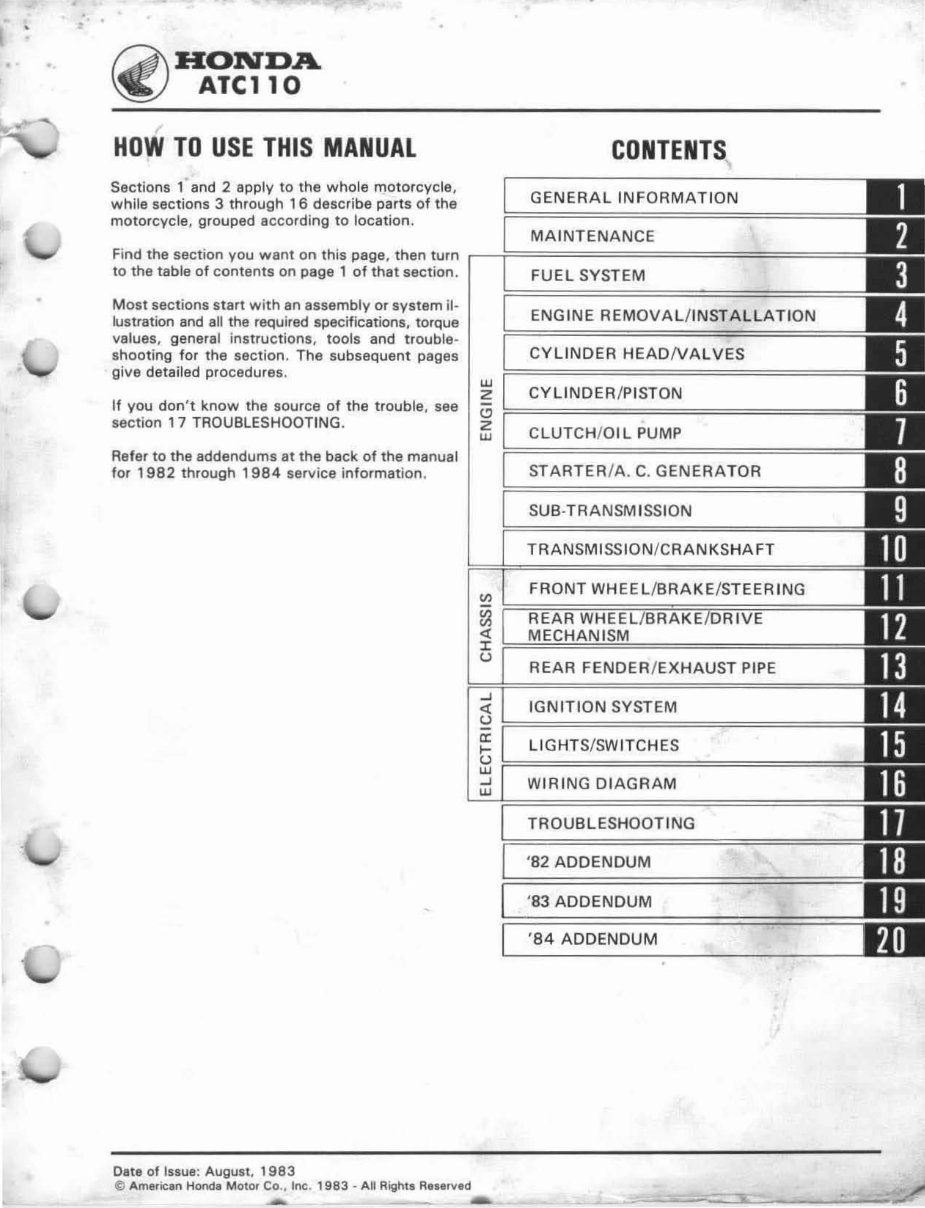
~ HON'DA
~ . ATCll0
H OW TO USE THIS MANUAL
Sections 1 and 2 apply to the whole motorcycle ,
while sections 3 through 16 describe parts of the
motorcycle, grouped according to location .
CONTENTS
GENERAL I NFORMAT ION
MA INTENANCE
Find the section you want on this page, then turn r--f=================
to the table of cantents on page 1 of that section .
Most sections s tart with an assembly or system il-
lustration and ali the required specifications. torque
values, general instructions, tools and trouble-
shooting for the section. The subsequent pages
give detailed procedures.
If you don 't know the source of the trouble , see
section 17 TROUBLESHOOTING .
Refer to the addendums at the back of the manual
for 1982 through 1984 service information .
Date of Issue: August, 1983
e AmeriCan Honda Motor CO., Inc. 1983 - A~ Rights R ••• rved
w
2
'"
2
w
FUEL SYSTEM
ENGINE REMOVAL /INSTAL LATION
CYLINOER HEADNALVES
CYLINDER / PISTON
CLUTCH/ OIL PUMP
STARTER/A. C. GENERATOR
SUB·TRANSMISSIDN
TRANSMISSION/CRANKSHAFT
FRONT WHEEL/BRAKE/STEERING
~~~~~~mw====
<{
J:
U
..J
<{
REAR FENDER /EXHAUST PIPE
IGN ITION SYSTEM
U p === ===== =====
a: LIGHTS /SW ITCHES
g ~===============================
WIRING DIAGRAM
TROUBLESHOOTING
'B2 ADDENDUM
'83 ADDENDUM
'84 ADDENDUM
~ -
-
"1i:. _ '
•
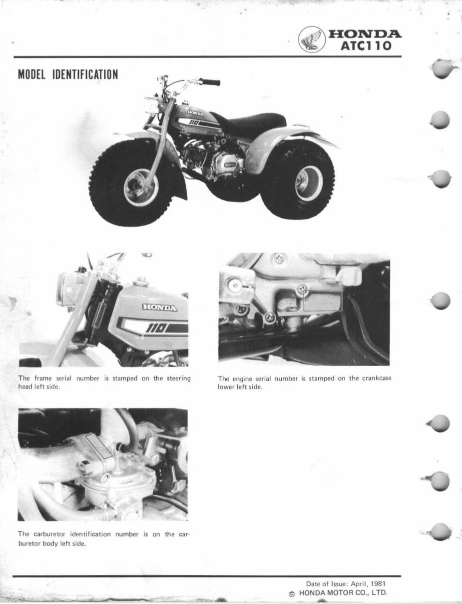
MOOEl IDENTIFICATION
- The trame serial number js stamped on the steering
head left side.
The carburetor ident ification number is on the car-
buretor body left side.
-
~ HONDA
~ AlellO
The engine ser ia l number is stamped on the crankcase
lower left sid e.
:...---
Date of Issue: Apr il, 1981
t9 HONOA MOTOR CO., L TO.
-""-
,
I
•
,
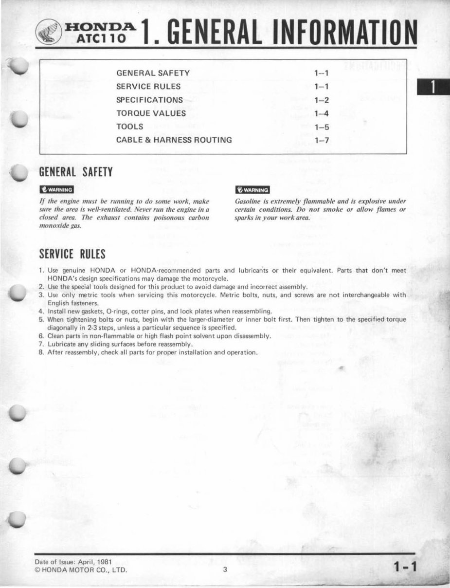
~ H~~?OA 1. GENERAL INFORMATION
GENERA L SAFETY 1- 1
SERVICE RULES 1- 1
SPE CIFICATIONS 1- 2
TOROU E VALUES 1-4
TOOLS 1 -5
CAB LE & HARNESS ROUTING 1- 7
GENERAL SAFETY
r§';ii!iiliJ cam ! ;it!!i!<'
If the engine musl be fIIm/ing 10 do some work, make
Slife ,lie area ;s ""II-"emilaled. Nel'l'f run the engine in a
closed arm. 171e exhaust contains poisonous carbon
monoxide gas.
Gasoline is extremely flammable and is t!xplosil'e under
cerIa;" conditiolls. Do "0 1 smoke or all ow flames or
slJOrkJ in YOllr k'ork area.
SERVICE RULES
1. Use genuine HONDA or HONDA-recommended parts and lubricants or their equivalent. Parts that don't meat
HONDA's design specifications may damage the motorcycle.
2. Use the special tools designed for this product to avoid damage and incorrect assembly.
3. Use only metric tools when servicing this motorcycle. Metric bolts, nuts, and screws are not interchangeable with
English fasteners.
4. Instart new gaskets, O·rings, cotter pins, and lock plates when reassembling.
5. When tightening bolts Of nuts, begin with the larger-diameter Of inner bolt first. Then tighten to the specified torque
diagonally in 2-3 steps, unless a particular sequence is specified.
6. Clean parts in non· flammable or high flash point solvent upon disassembly.
7. Lubricate any sliding surfaces before reassembly.
8. After reassembly, check all parts for proper installation and operation.
•
Date of Issue: April, 1981
© HONDA MOTOR CO., LTD. 3 1-1
GENE RAL INFORMATI ON
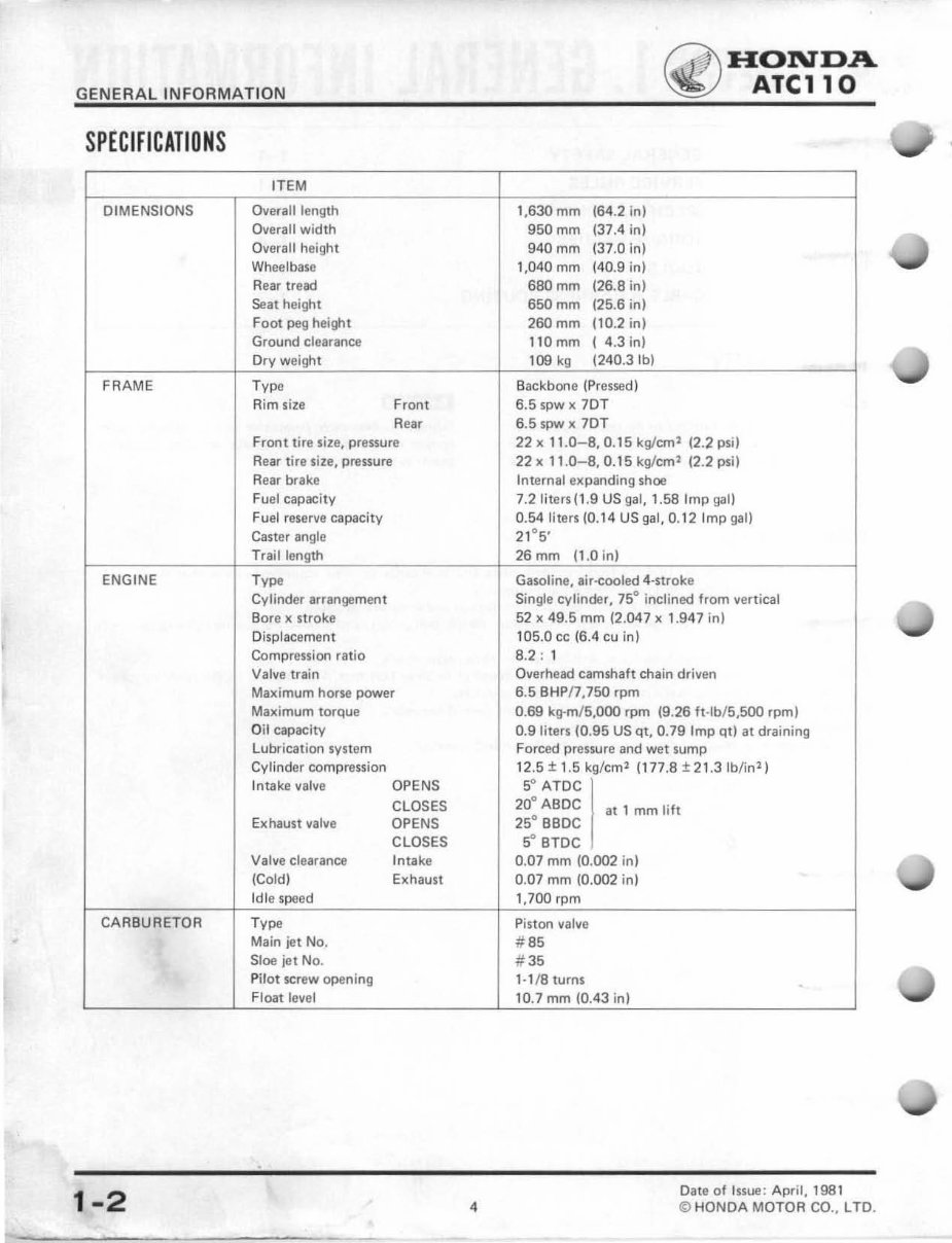
SP E Ci f iCATIONS
IT EM
DIMENSIONS Overall length
Overall width
Overall height
Wheelbase
Rear tread
Seat height
Foot peg height
Ground clearance
Dry weight
FRAME Type
Aim size Front
Rear
Front tire size, pressure
Rear tire size, pressure
Rear brake
Fuel capacity
Fuel reserve capacity
Caster angle
Trail length
ENGINE Ty".
Cylinder arrangement
Bore x stroke
Displacement
Compression ratio
Valve train
Maximum horse power
Maximum torque
Oil capacity
LUbl'ication system
Cylinder compression
Intake valve OPENS
CLOSES
Exhaust valve OPENS
CLOSES
Valve clearance Intake
(Cold) Exhaust
Idle speed
CARBURETOR Ty".
Main jet No.
Sloe jet No.
Pil ot screw openi ng
Float level
1-2
. -
4
1,630 mm (64.2 in)
950mm (37.4 in)
940mm (37.0 in)
1,040 mm (40.9 in)
680mm (26.8 in)
650mm (25.6 in)
260mm (10.2 in)
110 mm ( 4.3 in)
109 kg (240.3Ib)
Backbone (Pressed)
6.5 spw x 70T
6.5 spw x 7DT
~ HONDA
~ ATCll0
22 x 11.0-8,0. 15 kglcm
2
12.2 psi)
22 x 11 .0-8,0. 15 kg/em' (2.2 psi)
Internal e)(panding shoe
7.2Iiters(1.9 US gal, 1.58 Imp gal)
0.54 liters (0.14 US gal, 0.12 Imp gal)
2
1
°
5
,
26mrn (1.0 in)
Gasoline. air-cooled 4-stroke
Single cylinder, 75° inclined from vertical
52 x 49.5 mm (2.047 x 1.947 in)
105.0 cc (6.4 cu in)
8.2: 1
Overhead camshaft chain driven
6.5 BHP/7 ,750 rpm
0.69 kg·m/ 5,OOO rpm (9.26 ft .lb/ 5,5oo rpm)
0.9 liters (0.95 US qt, 0.79 Imp qt) at draining
Forced pressure and wet sump
12.5 ± 1.5 kg/cm
2
(177.8 ± 21.3 Ib/in
2
)
5° ATDC
20° ABDC
25° BBDC
at 1 mm lift
5° BTDC
0.07 mm (0.002 in)
0.07 mm (0.002 in)
1,700 rpm
Piston valve
# 85
#35
1· 1/ 8 turns
10.7 mm (0.43 in)
Date of Issue: April, 1981
<0 HONDA MOT OR CO. , LTD.
~ HONDA
~ ATCll0
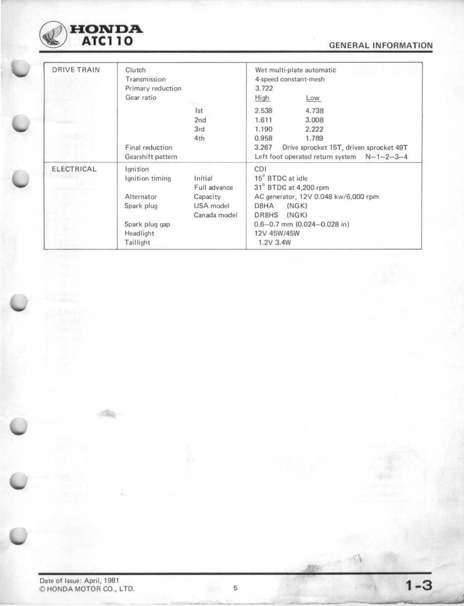
DRIVE TRAIN crutch
Transmission
Primary reduction
Gear ratio
Final reduction
Gearshift pattern
ELECTRICAL Ignition
Ignition timing
Alternator
Spark plug
Spark plug gap
Headlight
Tai llight
Date of Issue: April, 19S1
© HONDA MOTOR CO., LTD.
I"
2,d
3,d
4th
Initial
Full advance
Capacity
USA model
Canada model
5
GENERAL IN FOR MATI ON
Wet multi-plate automatic
4·speed constant-mesh
3.722
.!:!!..9!:!.
Low
2.538 4.738
1.6 11 3.008
1.190 2.222
0.958 1.789
3.267 Dri ve sprocket 15T, driven sprocket 49T
left foot operated return system N-1-2-3-4
CDI
15° BTDC at idle
31 ° BT OC at 4,200 rpm
AC generator, 12V 0. 048 k w/ B,OOO rpm
DSHA (NGK)
DR8HS INGKI
0.6- 0.7 mm (0.024-0 . 028 in)
12V 45W!45W
1.2V 3.4W
1-3
GENERAL INFORMATI ON
TORUUE VALUES
ENGINE
Item Q 'ty
Cylinder head nut 4
Camshaft sprocket bolt 2
Cam chain guide roller bolt I
Spark advancer bolt I
Clutch lock nut 1
AC generator rotor nut 1
Shift drum bolt I
FRAME
Item Q'ty
Steering stem nut 1
Fork top br idge bolt 2
Handlebar lower holder nut 2
Front ax le nut 2
Bra ke drum nut 2
Seat and rear fender 10
Engine hanger bolt 4
Intake pipe and carbure tor 2
Final driven sprocket nut 4
Gearsh i tt bolt 1
Fender and mud guard 11
Rear axl e nut 2
Fo ot peg bolt 4
Chain tensioner lock nut 1
Thread dia.
N 'm
(mm)
8 18- 20
6 8- 12
6 8- 12
6 8- 12
16 40- 50
14 65- 75
6 8- 12
Thread dia.
(mml
N·m
22 50- 70
12 50- 70
10 40 - 48
12 50- 70
32 40- 60
6 5- 7
8 19- 25
6 6- 9
10 44- 52
6 7- 12
4 5- 7
14 60- 80
8 19- 25
10 35- 45
~ HONDA
~ ATCll0
kg-m ft·lb
1.8- 2.0 13- 1("'"
0.8- 1.2 5.8- 8.7
0.8- 1.2 5.8- 8.7
0.8- 1.2 5.8- 8. 7
4.0- 5.0 29- 36
6.5- 7.5 47- 51
0.8- 1.2 5.8- 8.7""
kg-m ft·lb
5. 0-7 .0 36- 51
5. 0-7 .0 36- 51
4.0- 4.8 29- 35
5.0- 7.0 36 - 51
4.0-6 .0 29- 43
0.5- 0.7 3.6-5. 0
1.9-2 .5 14- 18
0.6- 0.9 4.3- 6.5
4.4- 5.2 32- 38
0.7- 1.2 5. 1-8.7
0.5- 0.7 3.6-5 .0
6.0- 8.0 43- 58
1.9- 2.5 14- 18
3.5- 4.5 25- 33
Torque specifications listed above are for the most important tightening points. If a torque specif ication is not listed, use
the standards given below.
STANDARD TORQ UE VALUES
Item TORQUE N·m (kg' m, ft ·lb) Item TORQUE N·m (kg·m, ft·lb)
5 mm bolt, nut 4.5- 6 (0.45- 0.6, 3.3 - 4.3) 5 mm screw 3.5- 5 (0.35-0.5,2.5- 3.6)
6 mm bolt, nut 8- 12 !O.8- 1.2, 5.8- 8.7) 6 mm screw 7- 11 (0.7- 1.1, 5- 8)
8 mm bolt, nut 18- 25 (1.8- 2. 5, 13- 18) 6 mm flange bolt, nut 10- 14 (1 .0- 1.4, 7.2- 10)
10 mm bolt, nut 30- 40 (3 .0- 4.0, 22- 29) 8 mm flange bolt, nut 24 - 30 (2.4- 3.0, 17 - 22)
12 mm bolt, nut 50- GO (5.0--4.0, 36--43) 10 mm flange bolt, nut 30--40 (3.0- 4.0, 22- 29)
1-4 6
Date of Issue: April, 1981
© HONDA MOTOR CO., lTD .
~ HON'DA
~ Ale110
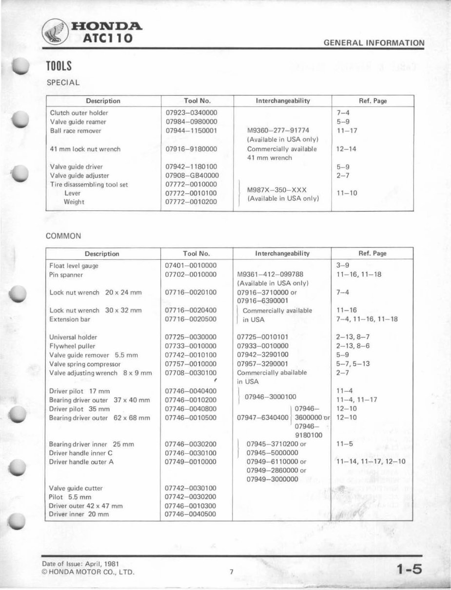
TOOLS
SP ECIAL
Description
Clutch outer holder
Valve !J.lide reamer
Ball race remover
41 mm lock nut wrench
Valve guide driver
Valve guide adjuster
Tire disassembling 1001 set
l ever
Weight
COMMON
Description
Float level gauge
Pin spanner
lock nut wrench 20 x 24 mm
lode nut wrench 30 x 32 mm
Extension bar
Universal holder
Flywheel puller
Valve guide remover 5.5 mm
Valve spring compressor
Vallie adjusting wrench B x 9 mm
Driver pilot 17 mm
Bearing driver outer 37)( 40 mm
Driver pilot 35 mm
Bearing driver outer 62)( 68 mm
Bearing driver inner 25 mm
Driver handle inner C
Driver handle outer A
Valve guide cutter
Pilot 5.5 mm
Driver outer 42 )( 47 mm
Driver inner 20 mm
Date of Issue : April, 1981
© HONDA MOTOR CO., lTD.
Tool No.
07923-0340000
07984-0980000
07944-1150001
07916-9180000
07942-1180100
07908-GB40000
07772-0010000
07772-0010100
07772-0010200
T ool No.
0740 1-0010000
07702-0010000
07716-0020100
07716-0020400
07716-0020500
07725-0030000
07733-00 10000
07742-00 10100
07757-00 10000
07708-0030100
,
07746-0040400
077 46-001 0200
077 46-0040800
07746-0010500
077 46-0030200
077 46 -00301 00
07749-00 10000
07742-0030100
07742-0030200
07746-00 10300
077 46 -0040500
7
GENERAL INFOR MATION
Interchangeability
M9360-277-9 1774
(Available in USA only)
Commercially available
41 mm wrench
I
M987X-J50-XXX
(Available in USA only)
Interchangea bil ity
M936 1-4 12-099788
(Available in USA on ly)
07916-3710000 or
07916-6390001
I
Commercially available
in USA
07725-00 10101
07933-0010000
07942-3290100
07957-3290001
Commerciallyabailable
in USA
1 07946-3000100
1
07946-
07947-6340400 3600000 or
07946-
9180100
I
07945-3710200 or
07945-5000000
07949-61 10000 or
07949-2860000 or
07949-3000000
Ref. Page
7-4
5-9
11-17
12-14
5-9
2-7
11-10
Ref. Page
3-9
11 - 16,1 1- 18
7-4
11-16
7- 4,11-16,11-18
2-13,8-7
2-13,8-6
5-9
5-7,5-13
2-7
11-4
11-4,11-17
12-10
12-10
11-5
11- 14 , 11 - 17,12-10
"
1-5
GENERAL INFORMATION
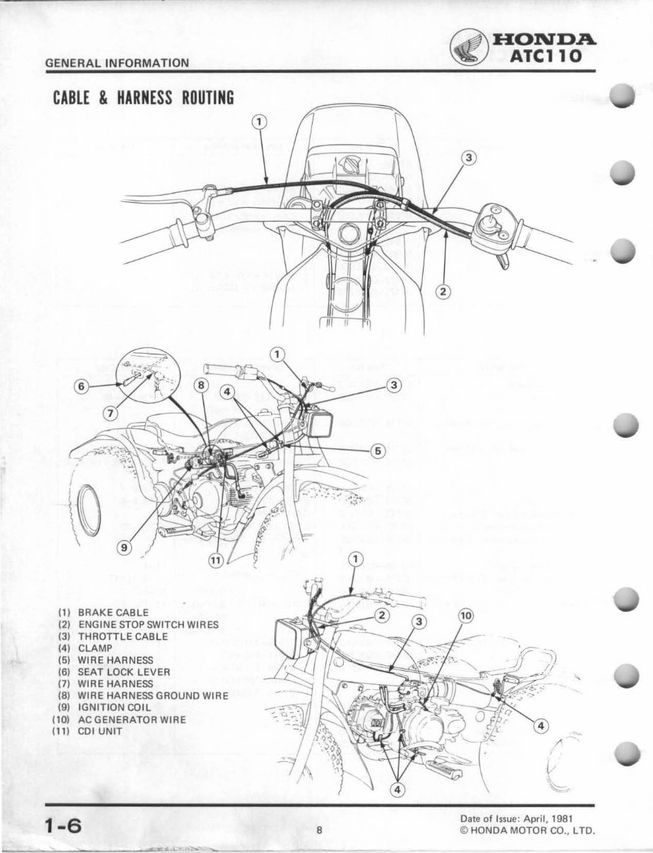
CABLE & HARNESS ROUTING
(1) BRAKE CABLE
(2) ENGINE STOP SWITCH WI RES
(3) THROTTLE CABLE
(4) CLAMP
(5) WIRE HARNESS
(6) SEAT LOCK LEVER
(7) WIRE HARNESS
(8) WIRE HARNESS GROUND WIRE
(9) IGNITION CO il
flO) AC GENERATOR WIRE
(11) COl UNIT
1-6
>-____ ___ ~·~xu·u,·~~ ~ ~~ __ _
8
rA!J\ HONDA
~ ATCll0
4
[-
.~
Dale of Issue : April , 1981
if) HONDA MOTOR CO. , LTD.
You're Reading a Preview
What's Included?
Fast Download Speeds
Online & Offline Access
Access PDF Contents & Bookmarks
Full Search Facility
Print one or all pages of your manual
$28.99
1981-1984 Honda ATC110 Service & Repair Manual
Viewed 70 Times Today

What's Included?
Fast Download Speeds
Online & Offline Access
Access PDF Contents & Bookmarks
Full Search Facility
Print one or all pages of your manual
$28.99

Secure transaction
What's Included?
Fast Download Speeds
Online & Offline Access
Access PDF Contents & Bookmarks
Full Search Facility
Print one or all pages of your manual
A comprehensive workshop manual that covers all repair and maintenance aspects, from engine rebuilds to spark plug replacement. This manual is essential for both professional mechanics and DIY enthusiasts. Simply print off the pages you need for easy reference.


