Harley Davidson FXDS-CONV Convertible 91-98 Service Manual
What's Included?
Lifetime Access
Fast Download Speeds
Online & Offline Access
Access PDF Contents & Bookmarks
Full Search Facility
Print one or all pages of your manual
CHAPTER ONE GENERAL INFORMATION This service shop manual covers the Harley- Davidson Dyna Glide produced from 1991-1998. Procedur es unique to 1996-1998 models are cov- ered in the supplement at the end of the manua l. Troubleshooting, tune-up, maintenance and re- pair are not difficult, if you know what tools and e qu i pm en t to u se an d what s tep s to follow. Step-by-step instructions guide you through jobs ranging from simple maintenance to engine and sus- pension repair . Anyone from a first time do-it yourself er to a profes- sional mechanic can use this manual. Detailed draw- ings and clear ph otographs give you the infonnation you need to work on your Dyna Glide correctl y. Table 1 li sts model coverage. Table 2 li sts general specifications. Table 3 li sts overall vehicle weight specification s. Table 4 lists gross vehicle weight ratings. Table S li sts fuel capacity. Table 6 lists U.S. to metric conversion. Metric and U.S. standards are used throughout this manual. Table 7 li sts general torque specifications. Criti- cal torque spec ifi cati ons are found in table fonn at the end of each chapter (as required). Use the gen- eral torque speci fi cations in Table 7 if a chapter ta- ble does not li st a torque specific tightening. Table 8 lists conversion tables. Table 9 lists tap drill sizes. Tables 1-9 are at the end of the chapter. MANUAL ORGANIZATION This chapter provides general information useful to Dyna Glide owners and mechanics. In addition, informati on in this chapter discusses the tools and techniques for preventive maintenance, trouble- shoot ing and repair. Chapter Two provides methods and suggestions for quick and accurate diagnosis of problems. Tro u- bleshooting procedures discuss typical symptoms and logi cal methods to pinpoint the cause of the trouble. Chapter Three explains all peri odic lub ri cation and routine maintenance necessary to keep your Dyna Glide operating well. Chapte r Three also include s recommend ed tune-up proce dures, eliminating the need to consult other chapters on the various assemblies. Subsequent chapters describe specific systems, providing disassemby, repair, assembly and adjust-
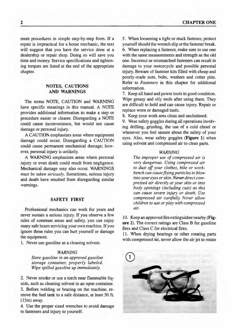
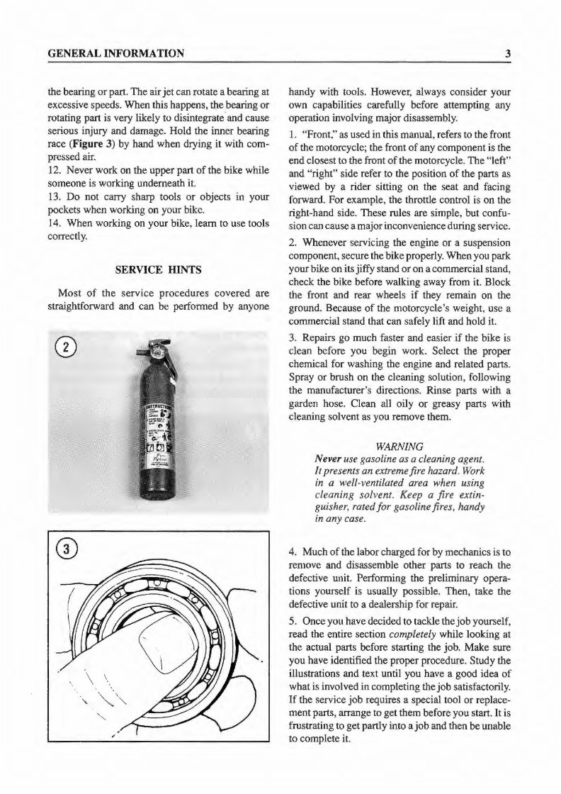
2 ment procedures in simple step-by-step form. If a repair is impractical for a home mechanic, the text will suggest that you have the service done at a dealership or repair shop. Doing so will save you time and money. Service specifications and tighten- ing torques are listed at the end of the appropriate chaptei: NOTES, CAUTIONS AND WARNINGS The terms NOTE, CAUTION and WARNING have specific meanings in this manual. A NOTE provides additional information to make a step or procedure easier or clearer. Disregarding a NOTE could cause inconvenience, but would not cause damage or personal injury. A CAUTION emphasizes areas where equipment damage could occur. Disregarding a CAUTION could cause permanent mechanical damage; how- ever, personal injury is unlikely. A WARNING emphasizes areas where personal injury or even death could result from negligence. Mechanical damage may also occur. WARNINGS must be taken seriously. Sometimes, serious injury and death have resulted from disregarding similar warnings. SAFETY FIRST Professional mechanics can work for years and never sustain a serious injury. If you observe a few rules of common sense and safety, you can enjoy many safe hours servicing your own machine. If you ignore these rules you can hurt yourself or damage the equipment. 1. Never use gasoline as a cleaning solvent. WARNING Store gasoline in an approved gasoline storage container, properly labeled. Wipe spilled gasoline up immediately. 2. Never smoke or use a torch near flammable liq- uids, such as cleaning solvent in an open container. 3. Before welding or brazing on the machine, re- move the fuel tank to a safe distance, at least 50 ft. (15m) away. 4. Use the proper sized wrenches to avoid damage to fasteners and injury to yourself. CHAPTER ONE 5. When loosening a tight or stuck fastener, protect yourself should the wrench slip or the fastener break. 6. When replacing a fastener, make sure to use one with the same measurements and strength as the old one. Incorrect or mismatched fasteners can result in damage to your motorcycle and possible personal injury. Beware of fastener kits filled with cheap and poorly-made nuts, bolts, washers and cotter pins. Refer to Fasteners in this chapter for additional information. 7. Keep all hand and power tools in good condition. Wipe greasy and oily tools after using them. They are difficult to hold and can cause injury. Repair or replace worn or damaged tools. 8. Keep your work area clean and uncluttered. 9. Wear safety goggles during all operations involv- ing drilling, grinding, the use of a cold chisel or whenever you feel unsure about the safety of your eyes. Also, wear safety goggles (Figure 1) when using solvent and compressed air to clean parts. WARNING The improper use of compressed air is very dangerous. Using compressed air to dust off your clothes, bike or work- bench can cause flying particles to blow into your eyes or skin. Never direct com- pressed air directly at your skin or into body openings (including cuts) as this can cause severe injury or death. Use compressed air carefully. Never allow children to use or play with compressed air. I 0. Keep an approved fire extinguishernearby (Fig- ure 2). The correct ratings are Class B for gasoline fires and Class C for electrical fires. 11. When drying bearings or other rotating parts with compressed air, never allow the air jet to rotate
GENERAL INFORMATION the bearing or part. The air jet can rotate a bearing at excessive speeds. When this happens, the bearing or rotating part is very likely to disi ntegrate-and cause serious injury and damage. Hold the inner bearing race (Figure 3) by hand when drying it with com- pressed air . 12. Never work on the upper part of the bike while someone is working underneath it. 13. Do not carry sharp tools or objects in your pockets when working on your bike. 14. When working on your bike, learn to use tools correctly. SERVICE HINTS Most of the serv ice proce dures covered are straightforward and can be performed by anyone 3 handy with tools. However, always consider your own capabilities carefully before attempting any operation involving major disassembly. 1. "Front ," as used in this manual, refers to the front of the motorcycle; the front of any component is the end closest to the front of the motorcycle. The "left" and "right" side r efer to the position of the parts as viewed by a rider sitting on the seat and facing forward. For example, the throttle control is on the right-hand side. These rules are simple, but confu- sion can cause a major inconvenience during service. 2. Whenever servicing the engine or a suspension component, secure the bike properly. When you park your bike on its jiffy stand or on a commercial stand, check the bike before walking away from it. Block the front and rear wheels if they remain on the ground. Because of the motorcycle's weight, use a commercial stand that can safely lift and hold it. 3. Repairs go much faster and easier if the bike is clean before you begin work. Select the proper chemical for washing the engine and related parts. Spray or brush on the cleaning solution, following the manufacturer's directions. Rinse parts with a garden hose. Clean all oily or greasy parts with cleaning solvent as you remove them. WARNING Never use gasoline as a cleaning agent. It presents an extreme fire hazard. Work in a well-ventilated area when using cleaning solvent. Keep a fire extin- guisher, rated for gasoline fires, handy in any case. 4. Much of the labor charged for by mechanics is to remove and disassemble other parts to reach the defective unit. Performing the preliminary opera- tions yourself is usually possible. Then, take the defective unit to a dealership for repair. 5. Once you have decided to tackle the job yourself, read the entire section completely while looking at the actual parts before starting th e job. Make sure you have identified the proper procedure. Study the illustrations and text until you have a good idea of what is involved in completing the job satisfactorily. If the service job requires a special tool or replace- ment parts, arrange to get them before you start. It is frustrating to get partly into a job and then be unable to complete it.
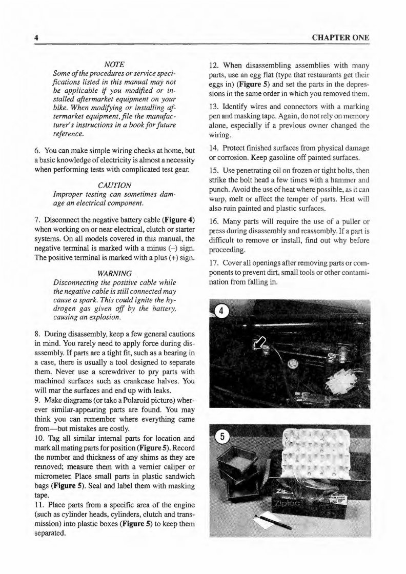
4 NOTE Some of the procedures or service speci- fications listed in this manual may not be applicable if you modified or in- stalled aftermarket equipment on your bike. When modifying or installing af- termarket equipment, file the manufac- turer's instructions in a book for future reference. 6. You can make simple wiring checks at home, but a basic knowledge of electricity is almost a necessity when performing tests with complicated test gear. CAUTION Improper testing can sometimes dam- age an electrical component. 7. Disconnect the negative battery cable (Figure 4) when working on or near electrical, clutch or starter systems. On all models covered in this manual, the negative terminal is marked with a minus (-) sign. The positive terminal is marked with a plus ( +) sign. WARNING Disconnecting the positive cable while the negative cable is still connected may cause a spark. This could ignite the hy- drogen gas given off by the batte1y, causing an explosion. 8. During disassembly, keep a few general cautions in mind. You rarely need to apply force during dis- assembl y. If parts are a tight fit, such as a bearing in a case, there is usually a tool designed to separate them. Never use a screwdriver to pry parts with machined surfaces such as crankcase halves. You will mar the surfaces and e nd up with leaks. 9. Make diagrams (or take a Polaroid picture) wher- ever similar-appearing parts are found. You may think you can remember where everything came from-but mistakes are costl y. 10. Tag all similar internal parts for location and mark all mating parts for position (Figure 5). Record the number and thickness of any shims as they are removed; measure them with a vernier caliper or micrometer. Place small parts in plastic sandwich bags (Figure 5). Seal and label them with masking tape. 11. Place parts from a specific area of the engine (such as cylinder heads, cylinders, clut ch and trans- mission) into plastic boxes (Figure 5) to keep them separated. CHAPTER ONE 12. When disassembling assemblies with many parts, use an egg flat (type that restaurants get their eggs in) (Figure 5) and set the parts in the depres- sions in the same order in which you removed them. 13. Identify wires and connectors with a marking pen and masking tape. Again, do not rely on memory alone, especially if a previous owner changed the wiring. 14. Protect finished surfaces from physical damage or corrosion. Keep gasoline off painted s urf aces. 15. Use penetrating oil on frozen or tight bolts, then strike the bolt head a few ti mes with a hammer and punch. Avoid the use of heat where possible, as it can warp, melt or affect the temper of parts. Heat will also ruin painted and plastic surf aces. 16. Many parts will require the use of a puller or press during disassembly and reassembl y. If a part is difficult to remove or install, find out why before proceeding. 17. Cover all openings after removing parts or com- ponents to prevent dirt, small tools or other contami- nation from falling in.
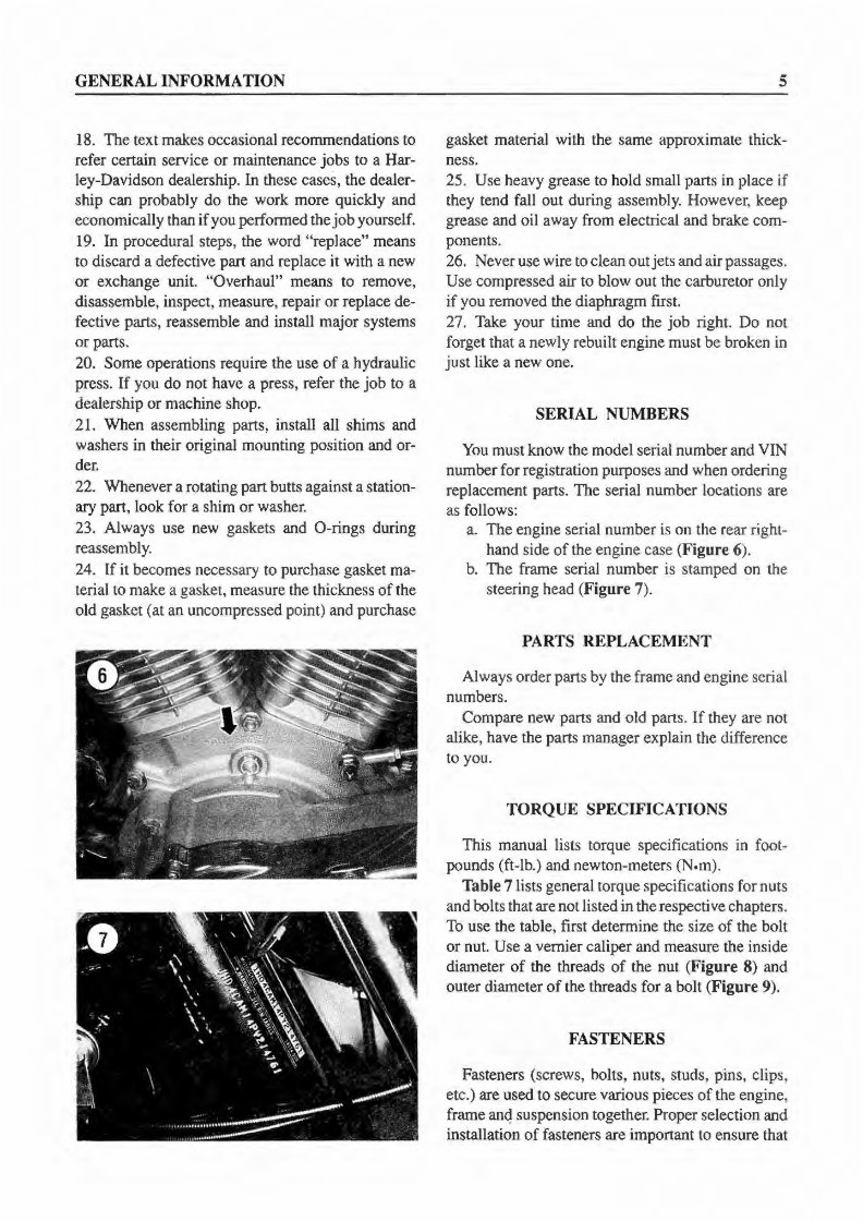
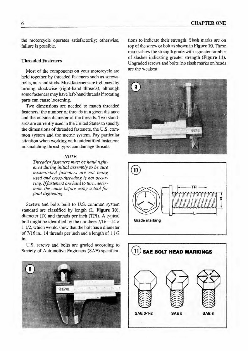
GENERAL INFORMATION 18. The text makes occasional recommendations to ref er certain service or maintenance jobs to a Har- ley-Davidson dealership. In these cases, the dealer- ship can probably do the work more quickly and economically than if you perfonned the job yourself. 19. In procedural steps, the word "replace" means to discard a defective part and replace it with a new or exchange unit. "Overhaul" means to remove, disassemble, inspect, measure, repair or replace de- fective parts, reassemble and install major systems or parts. 20. Some operations require the use of a hydrauli c press. If you do not have a press, refer the job to a dealership or machine shop. 21. When assembling part s, install all shims and washers in their original mounting position and or- der. 22. Whenever a rotating part butts against a station- ary part, look for a shim or washer. 23. Always use new gaskets and 0-rings during reassembl y. 24. If it becomes necessary to purchase gasket ma- terial to make a gasket, measure th e thickness of the old gasket (at an uncompressed point) and purchase 5 gasket material with the same approximate thick- ness. 25. Use heavy grease to hold small parts in place if they tend fall out during assembly. However, keep grease and oil away from electrical and brake com- ponents. 26. Never use wire to clean out jets and air passages. Use compressed air to blow out the carburetor only if you removed the diaphragm first. 27. Take your time and do the job right. Do not forget that a newly rebuilt engine must be broken in just like a new one. SERIAL NUMBERS You must know the model serial number and VIN number for registration purposes and when ordering replacement parts. The serial number lo cat ions are as follows: a. The engine serial number is on the rear right- hand side of the engine case (Figure 6). b. The frame serial number is stamped on the steering head (Figure 7). PARTS REPLACEMENT Always order parts by the frame and eng ine serial numbers. Compare new parts and old parts. If they are not alike, have the parts manager explain the difference to you. TORQUE SPECIFICATIONS This manual lists torque specifications in foot- pounds (ft-lb.) and newton-meters (N.m). Table 7 lists general torque spec ifi cations for nuts and bolts that are not listed in the respective chapters. To use the table, first determine the size of the bolt or nut. Use a vernier caliper and measure the inside diameter of the threads of the nut (Figure 8) and outer diameter of the threads for a bolt (Figure 9). FASTENERS Fasteners (screws, bolts, nuts, studs, pins, clips, etc.) are used to secure various pieces of the engine, frame anq suspension together. Proper selection and installation of fasteners are important to ensure that
6 the motorcycle operates satisfactorily; otherwise, failure is possible. Threaded Fasteners Most of the components on your motorcycle are held together by threaded fasteners such as screws, bolts, nuts and studs. Most fasteners are tightened by turning clockwi se (right-hand threads), although some fasteners may have left-hand threads if rotating parts can cause loosening. Two dimensions are needed to match threaded fasteners: the number of threads in a given distance and the outside diameter of the threads. Two stand- ards are currently used in the United States to specify the dimensions of threaded fasteners, the U.S. com- mon system and the metric system. Pay particular attention when working with unidentified fasteners; mismatching thread types can damage threads. NOTE Threaded fasteners must be hand tight- ened during initial assembly to be sure mismatched fasteners are not being used and cross-threading is not occur- ring. If fasteners are hard to turn, deter- mine the cause before using a tool for final tightening. Screws and bolts built to U.S. common system standard are classified by length (L, Figure 10), diameter (D) and threads per inch (TPI). A typical bolt might be identified by the numbers 7/16-14 x 1 1/2, which would show that the bolt has a diameter of 7 /16 in., 14 threads per inch and a length of 1 1 /2 in. U.S. screws and bolts are graded according to Society of Automotive Engineers (SAE) specifica- CHAPTER ONE tions to indicate their strength. Slash marks are on top of the screw or bolt as shown in Figure 10. These marks show the strength grade with a greater number of slashes indicating greater strength (Figure 11). Ungraded screws and bolts (no slash marks on head) are the weakest. Grade marking @sAE BOLT HEAD MARKINGS SAE 0-1 -2 SAE5 SAE8
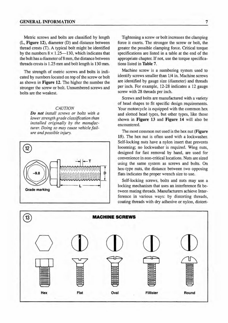
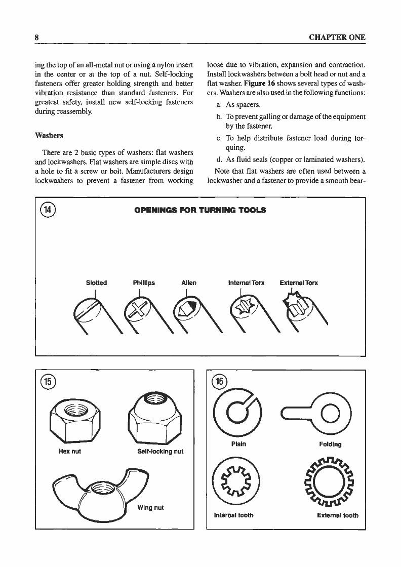
GENERAL INFORMATION Metric screws and bolts are classified by length (L, Figure 12), diameter (D) and distance between thread crests (T). A typical bolt might be identified by the numbers 8 x 1.25-130, which indicates that the bolt has a diameter of 8 mm, the distance between threads crests is 1 .25 mm and bolt length is 130 mm. The strength of metric screws and bolts is indi- cated by numbers located on top of the screw or bolt as shown in Figure 12. The higher the number the stronger the screw or bolt. Unnumbered screws and bolts are the weakest. CAUTION Do not install screws or bolts with a lower strength grade classification than installed originally by the manufac- turer. Doing so may cause vehicle fail- ure and possible injury. ® Grade marking 7 Tightening a screw or bolt increases the clamping force it exerts. The stronger the screw or bolt, the greater the possible clamping force. Critical torque specifications are listed in a table at the end of the appropriate chapter. If not, use the torque specifica- tions listed in Table 7. Machine screw is a numbering system used to identify screws smaller than 1/4 in. Machine screws are identified by gauge size (diameter) and threads per inch. For example, 12-28 indicates a 12 gauge screw with 28 threads per inch. Screws and bolts are manufactured with a variety of head shapes to fit specific design requirement s. Your motorcycle is equipped with the common hex and slotted head types, but other types, like those shown in Figure 13 and Figure 14 will also be encountered. The most common nut used is the hex nut (Figure 15). The hex nut is often used with a lockwasher. Self-locking nuts have a nylon insert that prevents loosening; no lockwasher is required. Wing nuts, designed for fast removal by hand, are used for convenience in non-critical locations. Nuts are sized using the same system as screws and bolts. On hex-type nuts, the distance between two opposing flats indicates the proper wrench size to use. Self-locking screws, bolts and nuts may use a locking mechanism that uses an interference fit be- tween mating threads. Manufacturers achieve Inter- ference in various ways: by distorting threads, coating threads with dry adhesive or nylon, distort- ® MACHINE SCREWS 0 CD CD CD CD Hex Flat Oval Fllllster Round
8 ing the top of an all-metal nut or using a nylon insert in the center or at the top of a nut. Self-locking fasteners offer greater holding strength and better vibration resistance than standard fasteners. For greatest safety, install new self-locking fasteners during reassembly. Washers There are 2 basic types of washers: flat washers and lockwashers. Flat washers are simple discs with a hole to fit a screw or bolt. Manufacturers design lockwashers to prevent a fastener from working CHAPTER ONE loose due to vibration, expansion and contraction. Install lockwashers between a bolt head or nut and a flat washer. Figure 16 shows several types of wash- ers. Washers are also used in the following functions: a. As spacers. b. To prevent galling or damage of the equipment by the fastener. c. To help distribute fastener load during tor- quing. d. As fluid seals (copper or laminated washers). Note that flat washers are often used between a lockwasher and a fastener to provide a smooth bear- ® OPENINGS FOR TURNING TOOLS Slotted Phllllps Allen Internal Tone External Tone ~~~ ~ Plain Folding Hex nut Self-locking nut lnteroal tooth External tooth
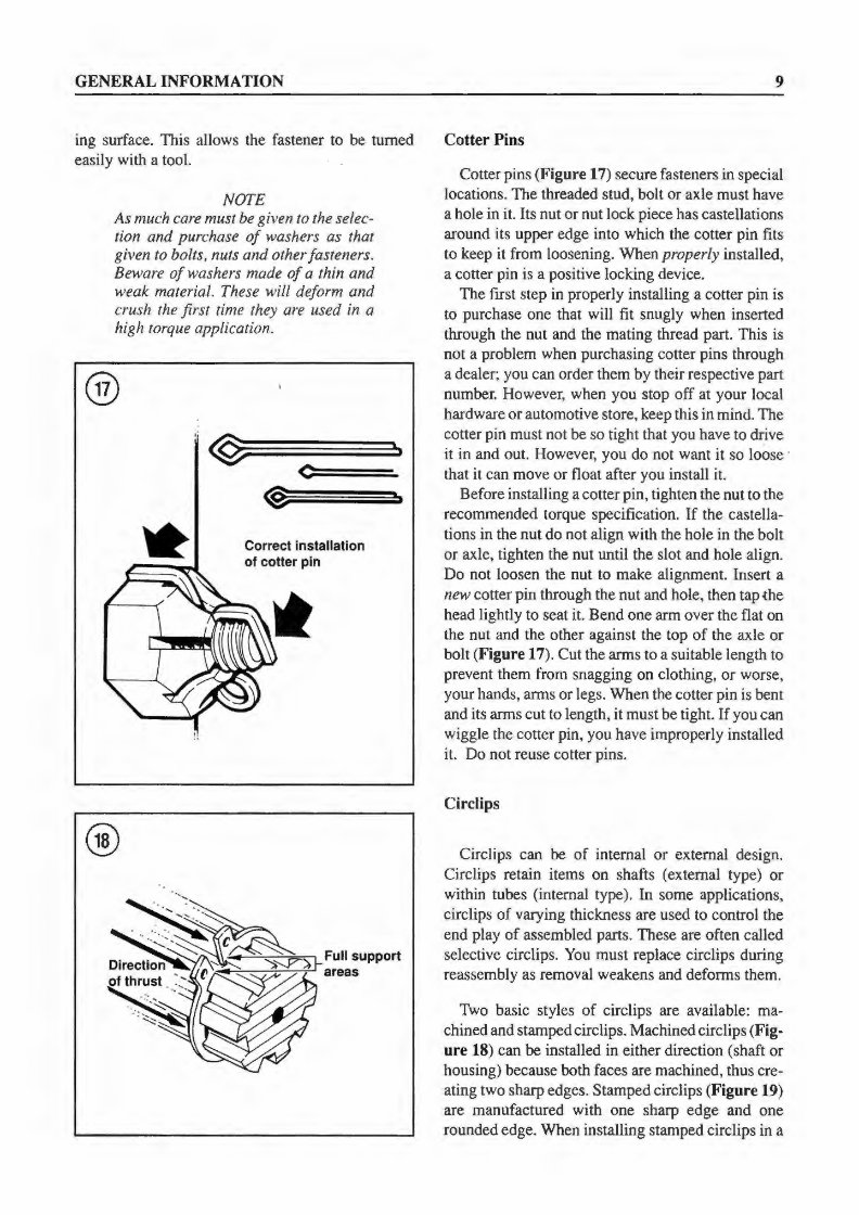
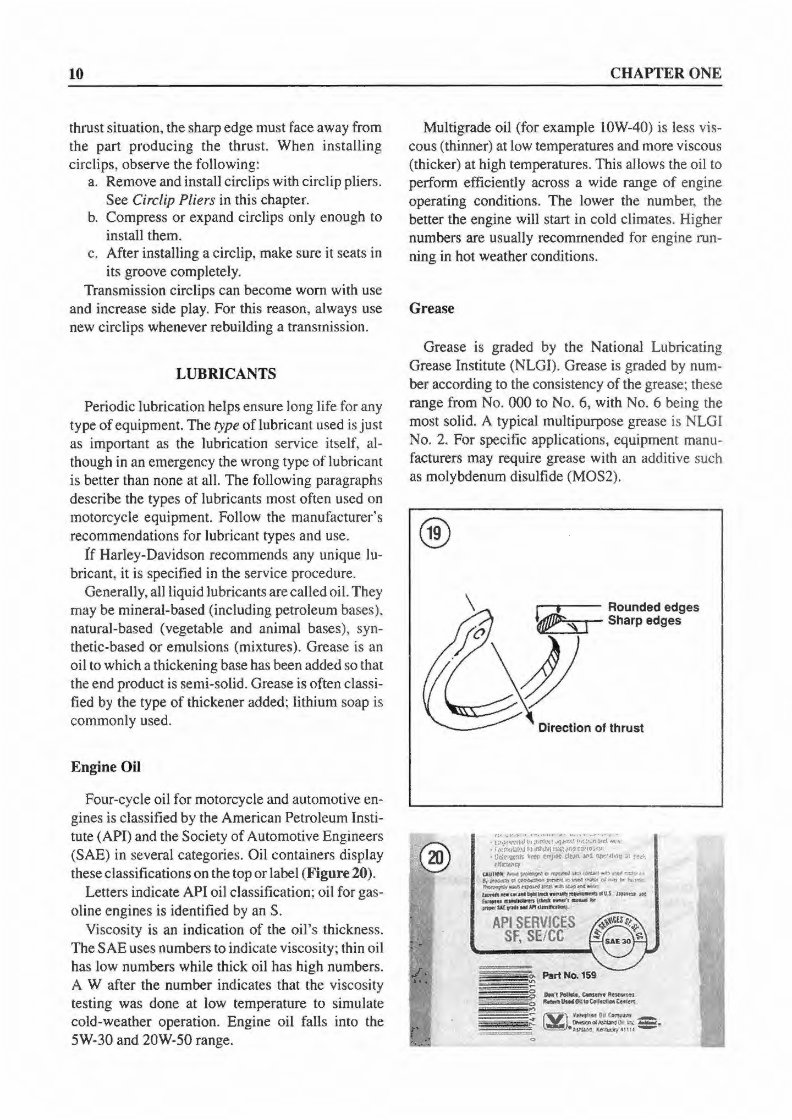
GENERAL INFORMATION ing surface. This allows the fastener to be turned easily with a tool. NOTE As much care must be given to the selec- tion and pur chase of washers as that given to bolts, nuts and other fasteners. Beware of washers made of a thin and weak material. These will deform and crush the first time they are used in a high torque application. ® @~====~·· c: Correct installation of cotter pin 9 Cotter Pins Cotter pins (Figure 17) secure fasteners in special locations. The threaded stud, bolt or axle must have a hole in it. Its nut or nut lock piece has castellations around its upper edge into which the cotter pin fits to keep it from loosening. When pr operly installed, a cotter pin is a positive locking device. The first step in properly installing a cotter pin is to purchase one that will fit snugly when inserted through the nut and the mating thread part. This is not a probl em when purchasing cotter pins through a dealer; you can order them by their respective part number. However, when you st op off at your local hardware or automotive store, keep this in mind. The cotter pin must not be so tight that you have to drive it in and out. However, you do not want it so loose · that it can move or fl oat after you install it. Before installing a cotter pin, tighten the nut to the recommended torque specification. If the castella- tions in the nut do not align with the hole in the bolt or axle, tighten the nut until the slot and hole align. Do not loosen the nut to make alignment. Insert a new cotter pin through the nut and hole, then tap the head li ghtly to seat it. Bend one arm over the fl at on the nut and the other against the top of the axle or bolt (Figure 17). Cut the arms to a suitable length to prevent them from snagging on clothing, or worse, your hands, arms or legs. When the cotter pin is bent and its arms cut to length, it must be tight. If you can wiggle the cotter pin, you have improperly installed it. Do not reuse cotter pins. Circlips Circlips can be of internal or external design. Circlips reta in items on shafts (external type) or within tubes (internal type). In some applications, circlips of varying thickness are used to control the end play of assembled parts. These are of ten called selective circlips. You must replace circlips during reassembly as removal weakens and deforms them. Two basic styles of circlips are available: ma- chined and stamped circlips. Machined c irclips (Fig- ure 18) can be installed in either direction (shaft or hous ing) because both faces are machined, thus cre- ating two sharp edges. Stamped circlips (Figure 19) are manufactured with one sharp edge and one rounded edge. When installing stamped circlips in a
10 thrust situation, the sharp edge must face away from the part producing the thrust. When installing circlips, observe the following: a. Remove and install circlips with circlip pliers. See Circlip Pliers in this chapter. b. Compress or expand circlips only enough to install them. c. After installing a circlip, make sure it seats in its groove completel y. Transmi ssion circlips can become worn with use and increase s ide play. For this reason, always use new circlips whenever rebuilding a transmission. LUBRICANTS Periodic lubrica tion helps ensure long life fo r any type of equipment. The type of lubrica nt used is just as important as the lubrication service itself, al- though in an emergency the wrong type of lubri cant is better than none at all. The following paragraphs describe the types of lubricants most of ten used on motorcycle equipmen t. Follow th e manufacturer's recommendations for lu bricant types and use. !f Harley-David son reco mmends any unique lu- bricant, it is specified in the service procedure. Generally, a ll liquid lubri ca nts are ca lled oil. They may be mineral-based (including petroleum bases), nat ural-based (vegetable and animal bases), syn- thetic-based or emulsions ( mi xtures). Grease is an oil to which a thickening base has been added so that the end pr o duct is semi-solid. Grease is of ten classi- fied by the type of thickener added; lithium soap is co mmo nl y used. E ngine Oil Four-cycle oil for motorcycle and automoti ve en- gines is class ified by the American Petroleum lnst i- tute (API) and the Society of Automotive Engineers (SAE) in several categories. Oil co ntainers display these classificat ions on the top or label ( Figure 20). Letters indicate AP I oil classificati on; oil for gas- oline engines is identified by an S. Vi scosity is an indication of the oil's thickness. The SAE uses numbers to indicate vi scosity; thin o il has low numbers while thick oil has high numbers. A W aft er the number indicates that the viscosity test ing was done at l ow temperatur e to simulate cold-weat her operation. Engi ne oil falls into the 5W-30 and 20W-50 range. CHAPTER ONE Multigrade oil (for example J OW-40) is less vi s- cous (thinner) at low temperatures and more viscous (thicker) at high temperatures. This allows the oil to perform efficiently across a wide range of engine operating conditions. The lower the number, the better the engine will start in cold climates. Higher numbers are usua ll y recommended for engine run- ning in hot weather conditions. Grease Grease is graded by the Nati onal Lubricating Grease In stitute (NLGI). Grease is graded by num- ber according to the co nsistency of the grease; these range from No. 000 to No. 6, with No. 6 being the most so lid. A typical multipurpose grease is NLGI No. 2. For specific appli cations, equipment manu- facturers may require grease wi th an additive such as molybdenum disulfide (MOS2). ® ~---- Rounded edges Sharp edges ,VI "J'04'" ',...,.,,,.... •· '"'•!.. ,, ., t :>~··'l"t1Hl It p.~f(1 ~q.t'.r.'i.l hr{l" P' ~"1 "M. c f0<!l1li!4.ll'J l.J ll'lhi..')11 iii~ t'l-11 r;wro:.·'lf1 • llctr1~' \, 't"r ~J~-t' elf~ ¥4 ~rM~ ~1 ~~~ "'1IOCl\c:y (:AUJlOlt'l-..~O 'ft'(.l"d "°fO'ILNI .. ..,~~~ .,..,.~°'~~ll lllid ~ol~':irfl:.a.~ ~~tt.'"'OWdV"AS.,.lt.Mlol(llll'M~ ~-- e«UlbflM.ntl•Ht .... ~-IU J- y,( ''""'" -~ ~---,..,.,..,. .....,w.,......,..,..,n~ API SERVICES SF, SE/ CC
The Harley Davidson FXDS-CONV Convertible Dyna 1991-1998 Service Manual / Workshop Repair is a comprehensive guide covering the repair and overhaul of the mentioned car models. It is designed for both professional mechanics and DIY enthusiasts, providing detailed instructions for various components and systems.
The manual includes tune-up, maintenance, removal & installation procedures, assemblies & disassemblies, fuel system, ignition, lubrication system, exhaust, electrical system, body, and more. It also covers extensive repair involving engine and transmission disassembly, making it a valuable resource for any repair needs.
By using this manual, technicians can understand the functions of proprietary components and judge the performance of the car as a whole. It aims to ensure the accuracy of the information provided, offering reliable instructions for maintaining and repairing the vehicles.
For those looking to perform maintenance and repairs themselves, this manual provides the necessary information and procedures, potentially saving time and money compared to dealership services. It emphasizes the importance of using safety equipment and precautions when working on the vehicles, including the use of torque wrenches and special tools as recommended.
Furthermore, the manual includes specifications and procedures available in authorized dealer service departments, offering diagnostic and repair procedures for various systems and components.
Additionally, the manual provides detailed information on general maintenance tasks such as air cleaner element renewal, battery maintenance, brake system checks, engine oil and filter renewal, exhaust system checks, fluid level inspections, and more.
This electronic manual is available in English and is delivered via email in .PDF format, ensuring fast and free access for users. It is a valuable resource for anyone seeking to better understand and maintain their Harley Davidson FXDS-CONV Convertible Dyna vehicles.
Recently Viewed
5,521,897Happy Clients
2,594,462eManuals
1,120,453Trusted Sellers
15Years in Business
Price:
Actual Price:
Harley Davidson FXDS-CONV Convertible 91-98 Service Manual