1993 Harley-Davidson Sportster Service & Repair Manual
What's Included?
Lifetime Access
Fast Download Speeds
Online & Offline Access
Access PDF Contents & Bookmarks
Full Search Facility
Print one or all pages of your manual
CHAPTER ONE GENERAL INFORMATION This detailed and comprehensive manual covers 1986-2003 XL/XLH Sportster models. The text provides complete information on maintenance, tune-up, repair and overhaul. Hundreds of photos and drawings guide the reader through every job. A shop manual is a reference tool and as in all Service manuals, the chapters are thumb tabbed for easy reference. Important items are indexed at the end of the book. All pro- cedures, tables and figures are designed for the reader who may be working on the motorcycle for the first time. Fre- quently used specifications and capacities from individual chapters are summarized in the Quick Reference Data at the front of this manual. MANUAL ORGANIZATION All dimensions and capacities are expressed in U.S. stan- dard and metric units of measurement. Specifications, when applicable, are listed in the tables at the end of each chapter. This chapter covers shop safety, tool use, service funda- mentals and shop supplies. Tables 1-12 at the end of the chapter include the following: 1. Model designations. 2. General motorcycle dimensions. 3. Motorcycle weight. 4. Gross vehicle weight. 5. Fuel tank capacity. 6. General torque recommendations. 7. Conversion formulas. 8. Technical abbreviations. 9. U.S. standard tap and drill sizes. 10. Metric tap and drill sizes. 11. Decimal and metric equivalents. 12. Special tools. Chapter Two provides methods for quick and accurate di- agnosis of problems. Troubleshooting procedures present typical symptoms and logical methods to pinpoint and re- pair the problem. Chapter Three explains all routine maintenance neces- sary to keep the motorcycle running well. Chapter Three also includes recommended tune-up procedures, eliminat- ing the need to constantly consult the chapters on the vari- ous assemblies. Subsequent chapters describe specific systems such as engine, primary drive and clutch, transmission, emissions, fuel and exhaust systems, the electrical system, suspension, brakes and body. Each disassembly, repair and assembly procedure is discussed in step-by-step form. 1
WARNINGS, CAUTIONS AND NOTES The terms, WARNING, CAUTION and NOTE have spe- cific meanings in this manual. A WARNING emphasizes areas where injury or even death could result from negligence. Mechanical damage may also occur. WARNINGS are to be taken seriously . A CAUTION emphasizes areas where equipment dam- age could result. Disregarding a CAUTION could cause permanent mechanical damage, though injury is unlikely. A NOTE provides additional information to make a step or procedure easier or clearer. Disregarding a NOTE could cause inconvenience, but would not cause equipment dam- age or personal injury. SAFETY Professional mechanics can work for years and never sus- tain a serious injury or mishap. Follow these guidelines and practice common sense to safely service the motorcycle. 1. Do not operate the motorcycle in an enclosed area. The exhaust gasses contain carbon monoxide, an odorless, col- orless and tasteless poisonous gas. Carbon monoxide levels build quickly in small enclosed areas and can cause uncon- sciousness and death in a short time. Make sure the work area is properly ventilated or operate the motorcycle outside. 2. Never use gasoline or any flammable liquid to clean parts. Refer to Handling Gasoline Safely and Cleaning Parts in this section. 3. Never smoke or use a torch in the vicinity of flammable liquids. 4. If welding or brazing on the motorcycle, remove the fuel tank, carburetor and shocks to a safe distance at least 50 ft. (15 m) away. 5. Use the correct type and size tools to avoid damaging fasteners. 6. Keep tools clean and in good condition. Replace or re- pair worn or damaged equipment. 7. When loosening a tight fastener, be guided by what would happen if the tool slips. 8. When replacing fasteners, make sure the new fasteners are of the same size and strength as the original ones. 9. Keep the work area clean and organized. 10. Wear eye protection any time eye safety is in question. This includes procedures involving drilling, grinding, ham- mering, compressed air and chemicals. 11. Wear the correct clothing for the job. Tie up or cover long hair so it can not get caught in moving equipment. 12. Do not carry sharp tools in clothing pockets. 13. Always have an approved fire extinguisher available. Make sure it is rated for gasoline (Class B) and electrical (Class C) fires. 14. Do not use compressed air to clean clothes, the motor- cycle or the work area. Debris may be blown into your eyes or skin. Never direct compressed air at anyone. Do not al- low children to use or play with any compressed air equipment. 15. When using compressed air to dry rotating parts, hold the part so it can not rotate. Do not allow the force of the air to spin the part. The air jet is capable of rotating parts at ex- treme speed. The part may be damaged or disintegrate, causing serious injury. 16. Do not inhale the dust created by brake pad and clutch wear. These particles may contain asbestos. In addition, some types of insulating materials and gaskets may contain asbestos. Inhaling asbestos particles is hazardous to health. 17. Never work on the motorcycle while someone is work- ing under it. 18. When placing the motorcycle on a stand, make sure it is secure before walking away. Handling Gasoline Safely Gasoline is a volatile flammable liquid and is one of the most dangerous items in the shop. Because gasoline is used so often, many people forget that it is hazardous. Only use gasoline as fuel for gasoline internal combustion engines. Keep in mind, when working on a motorcycle, gasoline is always present in the fuel tank, fuel line and carburetor. To avoid an accident when working around the fuel system, carefully observe the following precautions: 1. Never use gasoline to clean parts. See Cleaning Parts in this section. 2. Wear protective gloves to prevent skin contact with gas- oline. If your skin contacts gasoline, wash thoroughly with soap and water. 3. When working on the fuel system, work outside or in a well-ventilated area. 4. Do not add fuel to the fuel tank or service the fuel system while the motorcycle is near open flames, sparks or where someone is smoking. Gasoline vapor is heavier than air, it collects in low areas and is more easily ignited than liquid gasoline. 5. Allow the engine to cool completely before working on any fuel system component. 2 CHAPTER ONE 1
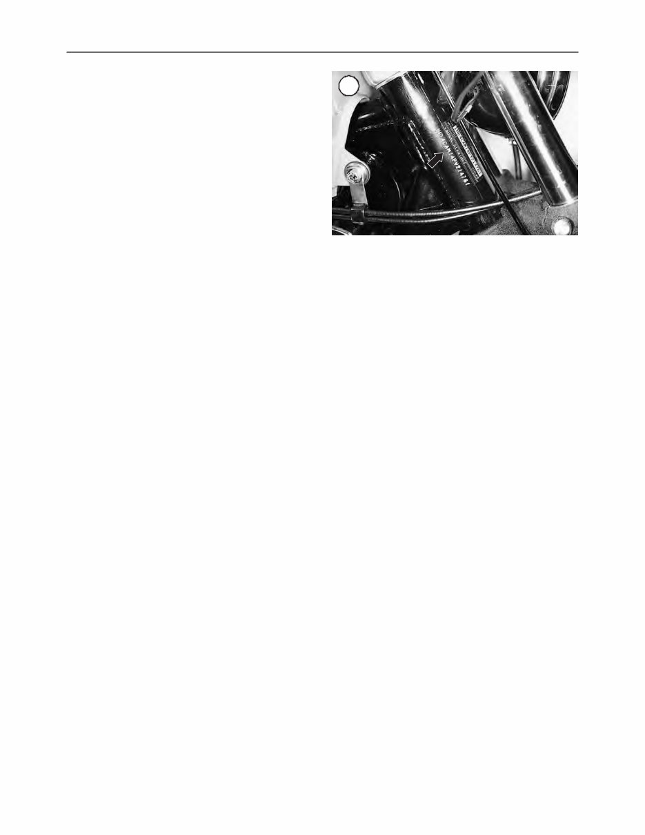
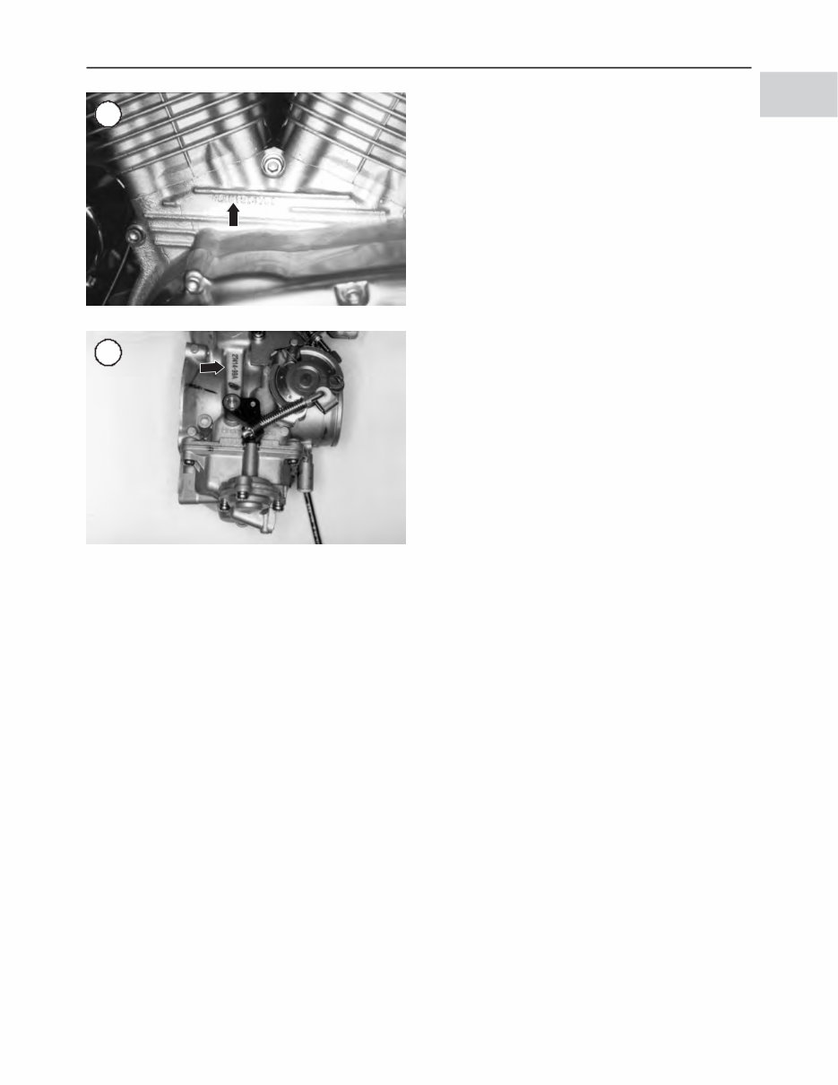
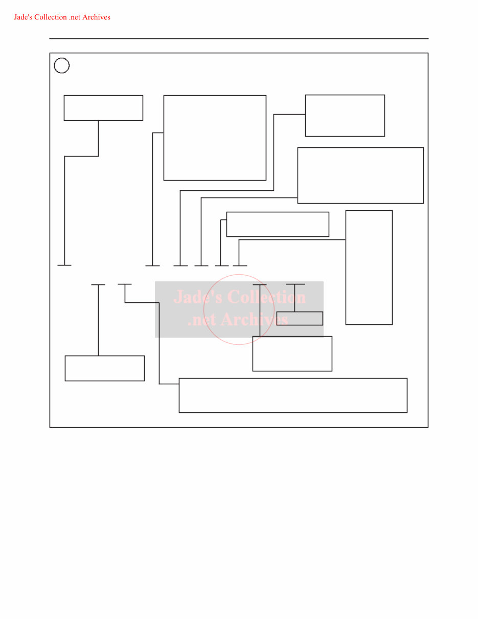
6. When draining the carburetor, catch the fuel in a plastic container and then pour it into an approved gasoline storage devise. 7. Do not store gasoline in glass containers. If the glass breaks, an explosion or fire may occur. 8. Immediately wipe up spilled gasoline with rags. Store the rags in a metal container with a lid until they can be properly disposed of, or place them outside in a safe place for the fuel to evaporate. 9. Do not pour water onto a gasoline fire. Water spreads the fire and makes it more difficult to put out. Use a class B, BC or ABC fire extinguisher to extinguish the fire. 10. Always turn off the engine before refueling. Do not spill fuel onto the engine or exhaust system. Do not overfill the fuel tank. Leave an air space at the top of the tank to al- low room for the fuel to expand due to temperature fluctuations. Cleaning Parts Cleaning parts is one of the more tedious and difficult service jobs performed in the home garage. There are many types of chemical cleaners and solvents available for shop use. Most are poisonous and extremely flammable. To pre- vent chemical exposure, vapor buildup, fire and serious in- jury, observe each product warning label and note the following: 1. Read and observe the entire product label before using any chemical. Always know what type of chemical is being used and whether it is poisonous and/or flammable. 2. Do not use more than one type of cleaning solvent at a time. If mixing chemicals is called for, measure the proper amounts according to the manufacturer. 3. Work in a well-ventilated area. 4. Wear protective gloves. 5. Wear safety glasses. 6. Wear a vapor respirator if the instructions call for it. 7. Wash hands and arms thoroughly after cleaning parts. 8. Keep chemical products away from children and pets. 9. Thoroughly clean all oil, grease and cleaner residue from any part that must be heated. 10. Use a nylon brush to clean parts. Metal brushes may cause a spark. 11. When using a parts washer, only use the solvent recom- mended by the manufacturer. Make sure the parts washer is equipped with a metal lid that will lower in case of fire. Warning Labels Most manufacturers attach information and warning la- bels to the motorcycle. These labels contain instructions that are important to personal safety when operating, ser- vicing, transporting and storing the motorcycle. Refer to the owner’s manual for the description and location of la- bels. Order replacement labels from the manufacturer if they are missing or damaged. SERIAL NUMBERS Serial numbers are stamped on various locations on the frame, engine and carburetor. Record these numbers in the Quick Reference Data section in the front of the book. Have these numbers available when ordering parts. The VIN number is stamped on the right side of the steer- ing head (Figure 1). The VIN number also appears on a la- bel affixed to the right, front frame downtube. The engine serial number is stamped on a pad at the left side surface of the crankcase between the cylinders (Figure 2). The engine serial number consists of digits used in the VIN number. The carburetor serial number (Figure 3) is located adja- cent to the accelerator pump linkage. NOTE In addition to model year designations, Harley-Davidson also uses early and late model designations. Refer to the “Introduc- tion Date and Special Models” information in Figure 4 to help determine the model iden- tity of a motorcycle. If in doubt, take the VIN number to a dealership. GENERAL INFORMATION 3 1 2 3
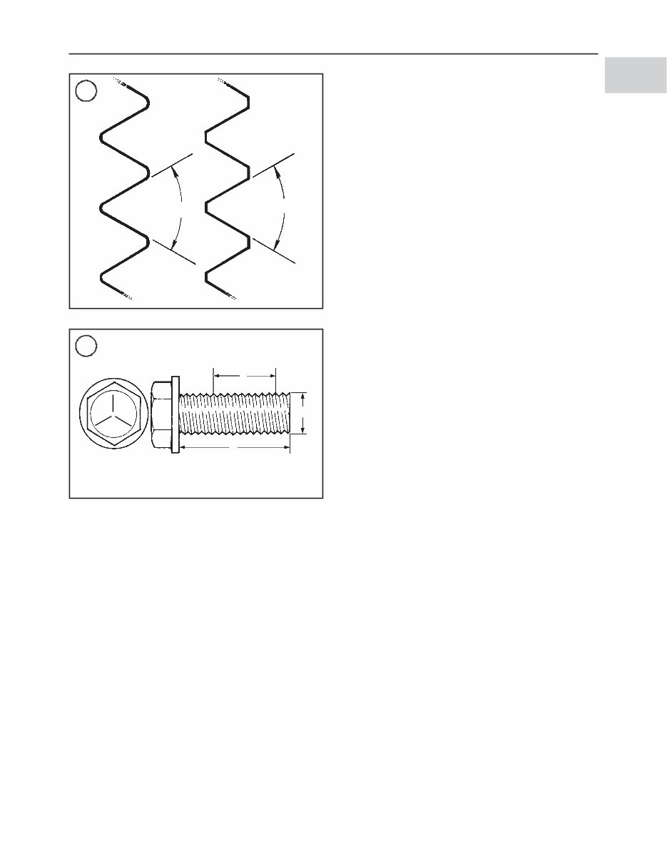
FASTENERS Proper fastener selection and installation is important to ensure the motorcycle operates as designed and can be ser- viced efficiently. The choice of original equipment fasten- ers is not arrived at by chance. Make sure that replacement fasteners meet all the same requirements as the originals. Threaded Fasteners WARNING Do not install fasteners with a strength classi- fication lower than what was originally in- stalled by the manufacturer. Doing so may cause equipment failure and/or damage. Threaded fasteners secure most of the components on the motorcycle. Most are tightened by turning them clockwise (right-hand threads). If the normal rotation of the compo- nent being tightened would loosen the fastener, it may have left-hand threads. If a left-hand threaded fastener is used, it is noted in the text. Two dimensions are required to match the size of the fas- tener: the number of threads in a given distance and the out- side diameter of the threads. Two systems are currently used to specify threaded fas- tener dimensions: the U.S. Standard system and the metric system (Figure 5). Pay particular attention when working with unidentified fasteners; mismatching thread types can damage threads. 4 CHAPTER ONE 4 VEHICLE IDENTIFICATION NUMBER (VIN) (1986-2003 SPORTSTER) Motorcycle Made in U.S.A. Model Designation CA = XLH883, XLH883 Deluxe (1986/1987), XLH1100, XLH1200 CE = XLH883 Hugger CF = XLH833 Deluxe CG = XL1200 Custom CH = XL1200 Sport CJ = XLH883 Custom CK = XLH883 Custom Engine Size M = 883 cc engine N = 1100 cc engine P = 1200 cc engine Introduction Date and Special Models 1 = Regular introduction date 2 = Mid-year introduction date 3 = California model 4 = Special edition 5 = California-only special edition VIN Check Digit Varies; can be 0 through 9, or X. Model Year M = 1991 N = 1992 P = 1993 R = 1994 S = 1995 T = 1996 V = 1997 W = 1998 X = 1999 Y = 2000 1 = 2001 2 = 2002 3 = 2003 Serial Number Assembly Plant K = Kansas City Y = York, Pennsyvania Motorcycle Type 1 = Heavyweight (901 cc and larger engine displacement) 4 = Middleweight (351-900 cc engine displacement) Manufacturer and Make Harley Davidson 1 HD 4 CA M 1 3 R Y Y
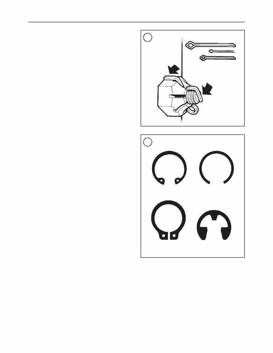
NOTE To ensure that the fastener threads are not mismatched or cross-threaded, start all fas- teners by hand. If a fastener is hard to start or turn, determine the cause before tightening with a wrench. The length (L, Figure 6), diameter (D) and number of threads per inch (TPI) (T) classify U.S. Standard screws and bolts. A typical bolt may be identified by the numbers 1/4–20×1-1/2. This indicates the bolt has a 1/4-inch diame- ter, 20 threads per inch and the length is 1-1/2 inches. Sometimes thread count is noted as either course or fine. Always measure bolt length as shown in L, Figure 6 to avoid purchasing replacements of the wrong length. Markings on top of the fastener (Figure 6) indicate the strength of U.S. Standard screws and bolts. The greater the number of head markings, the stronger the fastener. Un- marked fasteners are the weakest. Many screws, bolts and studs are combined with nuts to secure particular components. To indicate the size of a nut, manufacturers specify the internal diameter and the TPI. The measurement across two flats on a nut or bolt indi- cates the wrench size. Torque Specifications The materials used in the manufacture of the motorcycle may be subjected to uneven stresses if the fasteners of the various subassemblies are not installed and tightened cor- rectly. Fasteners that are improperly installed or work loose can cause extensive damage. It is essential to use an accu- rate torque wrench, as described in this chapter, with the torque specifications in this manual. Specifications for torque are provided in foot-pounds (ft.-lb.), inch-pounds (in.-lb.) and Newton-meters (N•m). Refer to Table 6 for general torque specifications. To use Table 6, first determine the size of the fastener as described in this section. Torque specifications for specific compo- nents are at the end of the appropriate chapters. Torque wrenches are covered in this chapter. Self-Locking Fasteners Several types of bolts, screws and nuts incorporate a sys- tem that creates interference between the two fasteners. In- terference is achieved in various ways. The most common types are the nylon insert nut and a dry adhesive coating on the threads of a bolt. Self-locking fasteners offer greater holding strength than standard fasteners, which improves their resistance to vi- bration. Self-locking fasteners cannot be reused. The mate- rial used to form the lock becomes distorted after the initial installation and removal. Discard and replace self-locking fasteners after their removal. Do not replace self-locking fasteners with standard fasteners. Washers There are two basic types of washers: flat washers and lockwashers. Flat washers are simple discs with a hole to fit a screw or bolt. Lockwashers are used to prevent a fastener from working loose. Washers can be used as spacers and seals, or to help distribute fastener load and to prevent the fastener from damaging the component. As with fasteners, when replacing washers make sure the replacement washers are of the same design and quality. Cotter Pins A cotter pin is a split metal pin inserted into a hole or slot to prevent a fastener from loosening. In certain applica- tions, such as the rear axle on a motorcycle, the fastener must be secured in this way. For these applications, a cotter pin and castellated (slotted) nut are used. To use a cotter pin, first make sure the diameter is correct for the hole in the fastener. After correctly tightening the GENERAL INFORMATION 5 1 U.S. Standard Metric 60° 60° 5 6 Grade marking T L D
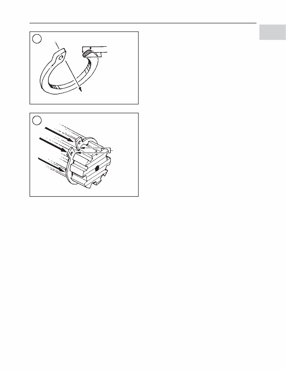
fastener and aligning the holes, insert the cotter pin through the hole and bend the ends over the fastener (Figure 7). Un- less instructed to do so, never loosen a tightened fastener to align the holes. If the holes do not align, tighten the fastener just enough to achieve alignment. Cotter pins are available in various diameters and lengths. Measure length from the bottom of the head to the tip of the shortest pin. Snap Rings and E-clips Snap rings (Figure 8) are circular-shaped metal retaining clips. They are required to secure parts and gears in place on parts such as shafts, pins or rods. External type snap rings are used to retain items on shafts. Internal type snap rings secure parts within housing bores. In some applica- tions, in addition to securing the component(s), snap rings of varying thickness also determine endplay. These are usu- ally called selective snap rings. Two basic types of snap rings are used: machined and stamped snap rings. Machined snap rings can be installed in either direction, since both faces have sharp edges. Stamped snap rings (Figure 9) are manufactured with a sharp edge and a round edge. When installing a stamped circlip in a thrust application, install the sharp edge facing away from the part producing the thrust (Figure 10). E-clips are used when it is not practical to use a circlip. Remove E-clips with a flat blade screwdriver by prying be- tween the shaft and E-clip. To install an E-clip, center it over the shaft groove and push or tap it into place. Observe the following when installing snap rings: 1. Remove and install snap rings with circlip pliers. Refer to the Tools section in this chapter. 2. In some applications, it may be necessary to replace snap rings after removing them. 3. Compress or expand snap rings only enough to install them. If overly expanded, they lose their retaining ability. 4. After installing a snap ring, make sure it seats com- pletely. 5. Wear eye protection when removing and installing snap rings. SHOP SUPPLIES Lubricants and Fluids Periodic lubrication helps ensure a long service life for any type of equipment. Using the correct type of lubricant is as important as performing the lubrication service, al- though in an emergency the wrong type is better than not using one. The following section describes the types of lu- bricants most often required. Make sure to follow the man- ufacturer’s recommendations for lubricant types. Engine oils Engine oil is classified by two standards: the American Petroleum Institute (API) service classification and the So- ciety of Automotive Engineers (SAE) viscosity rating. This information is on the oil container label. Two letters indi- cate the API service classification. The number or sequence of numbers and letter (10W-40 for example) is the oil’s vis- cosity rating. The API service classification and the SAE viscosity index are not indications of oil quality. The service classification indicates that the oil meets spe- cific lubrication standards. The first letter in the classifica- tion, S, indicates the oil is for gasoline engines. 6 CHAPTER ONE 7 Correct installation of cotter pin 8 Internal snap ring Plain circlip External snap ring E-clip
When selecting an API classified oil, make sure the clas- sification is correct (Chapter Three, Table 3) and the circu- lar API service label does not indicate the oil is for ENERGY CONSERVING. This type of oil is not designed for motorcycle applications. Using oil with the incorrect classification can cause engine damage. In addition to the API classification, some oils carry the Japanese Automobile Standards Organization (JASO) clas- sification for use in motorcycle engines. These motorcycle specific oils (JASO T 903 Standard) with the MA (high-friction applications) designation are designed for motorcycle applications. Always use an oil with a classification recommended by the manufacturer. Using an oil with a different classifica- tion can cause engine damage. Viscosity is an indication of the oil’s thickness. Thin oils have a lower number while thick oils have a higher number. Engine oils fall into the 5- to 50-weight range for sin- gle-grade oils. Most manufacturers recommend multi-grade oil. These oils perform efficiently across a wide range of operating conditions. Multi-grade oils are identified by a W after the first number, which indicates the low-temperature viscosity. Engine oils are most commonly mineral (petroleum) based; however, synthetic and semi-synthetic types are be- ing used more frequently. When selecting engine oil, fol- low the manufacturer’s recommendation for type, classification and viscosity when selecting engine oil. Re- fer to Chapter Three, Table 3. Greases Grease is lubricating oil with thickening agents added to it. The National Lubricating Grease Institute (NLGI) grades grease. Grades range from No. 000 to No. 6, with No. 6 being the thickest. Typical multipurpose grease is NLGI No. 2. For specific applications, manufacturers may recommend water-resistant grease or one with an additive such as molybdenum disulfide (MoS 2 ). Brake fluid WARNING Never put a mineral-based (petroleum) oil into the brake system. Mineral oil will cause rubber parts in the system to swell and break apart, resulting in complete brake failure. Brake fluid is the hydraulic fluid used to transmit hydrau- lic pressure (force) to the wheel brakes. Brake fluid is clas- sified by the Department of Transportation (DOT). This classification, DOT 5 for example, appears on the fluid container. Each type of brake fluid has its own definite characteris- tics. Do not intermix different types of brake fluid as this may cause brake system failure. DOT 5 brake fluid is sili- cone based. DOT 5 is not compatible with other brake flu- ids or in systems for which it was not designed. Mixing DOT 5 fluid with other fluids may cause brake system fail- ure. When adding brake fluid, only use the fluid recom- mended by the manufacturer. Refer to Chapter Three, Table 5. Brake fluid will damage any plastic, painted or plated surface it contacts. Use care when working with brake fluid and clean any spills immediately with soap and water. Hydraulic brake systems require clean and moisture free brake fluid. Never reuse brake fluid. Keep containers and reservoirs properly sealed. Coolant Coolant is a mixture of water and antifreeze used to dissi- pate engine heat. Ethylene glycol is the most common form of antifreeze used. Check the motorcycle manufacturer’s recommendations (Chapter Three, Table 5) when selecting antifreeze; most require one specifically designed for use in aluminum engines. These types of antifreeze have additives that inhibit corrosion. GENERAL INFORMATION 7 1 10 Direction of thrust Full support areas 9 Direction of thrust Rounded edges Sharp edges
Only mix distilled water with antifreeze. Impurities in tap water may damage internal cooling system passages. Cleaners, Degreasers and Solvents Many chemicals are available to remove oil, grease and other residue from the motorcycle. Before using cleaning solvents, consider how they will be used and disposed of, particularly if they are not water-soluble. Local ordinances may require special procedures for the disposal of many types of cleaning chemicals. Refer to Safety in this chapter for more information on their use. Use brake parts cleaner to clean brake system compo- nents, contact with petroleum-based products will damage seals. Brake parts cleaner leaves no residue. Use electrical contact cleaner to clean electrical connections and compo- nents without leaving any residue. Carburetor cleaner is a powerful solvent used to remove fuel deposits and varnish from fuel system components. Use this cleaner carefully, as it may damage finishes. Generally, degreasers are strong cleaners used to remove heavy accumulations of grease from engine and frame com- ponents. Most solvents are designed to be used with a parts wash- ing cabinet for individual component cleaning. For safety, use only nonflammable or high flash point solvents. Gasket Sealant Sealants are often used in combination with a gasket or seal and are occasionally alone. Follow the manufacturer’s recommendation when using sealants. Use care when choosing a sealant different from the type originally recom- mended. Choose sealants based on their resistance to heat, various fluids and their sealing capabilities. One of the most common sealants is RTV, or room tem- perature vulcanizing sealant. This sealant cures at room temperature over a specific time period. This allows the re- positioning of components without damaging gaskets. Moisture in the air causes the RTV sealant to cure. Al- ways install the tube cap as soon as possible after applying RTV sealant. RTV sealant has a limited shelf life and will not cure properly if the shelf life has expired. Keep partial tubes sealed and discard them if they have surpassed the ex- piration date. Applying RTV sealant Clean all old gasket residue from the mating surfaces. Remove all gasket material from blind threaded holes; it can cause inaccurate bolt torque. Spray the mating surfaces with aerosol parts cleaner and then wipe with a lint-free cloth. The area must be clean for the sealant to adhere. Apply RTV sealant in a continuous bead 0.08-0.12 in. (2-3 mm) thick. Circle all the fastener holes unless other- wise specified. Do not allow any sealant to enter these holes. Assemble and tighten the fasteners to the specified torque within the time frame recommended by the RTV sealant manufacturer. Gasket Remover Aerosol gasket remover can help remove stubborn gas- kets. This product can speed up the removal process and prevent damage to the mating surface that may be caused by using a scraping tool. Most of these types of products are very caustic. Follow the gasket remover manufacturer’s instructions for use. Threadlocking Compound CAUTION Threadlocking compounds are anaerobic and will damage most plastic parts and sur- faces. Use caution when using these prod- ucts in area where plastic components are located. A threadlocking compound is a fluid applied to the threads of fasteners. After tightening the fastener, the fluid dries and becomes a solid filler between the threads. This makes it difficult for the fastener to work loose from vibration, or heat expansion and contraction. Some threadlocking compounds also provide a seal against fluid leaks. Before applying threadlocking compound, remove any old compound from both thread areas and clean them with aerosol parts cleaner. Use the compound sparingly. Excess fluid can run into adjoining parts. Threadlocking compounds are available in different strength, temperature and repair application. Follow the manufacturer’s recommendations regarding compound se- lection. TOOLS Most of the procedures in this manual can be carried out with simple hand tools and test equipment familiar to the 8 CHAPTER ONE 11
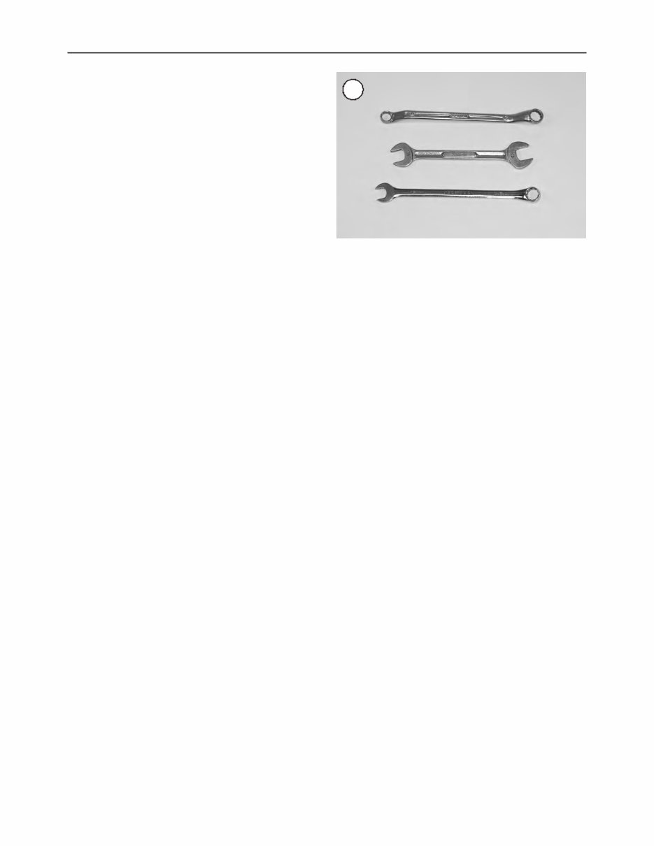
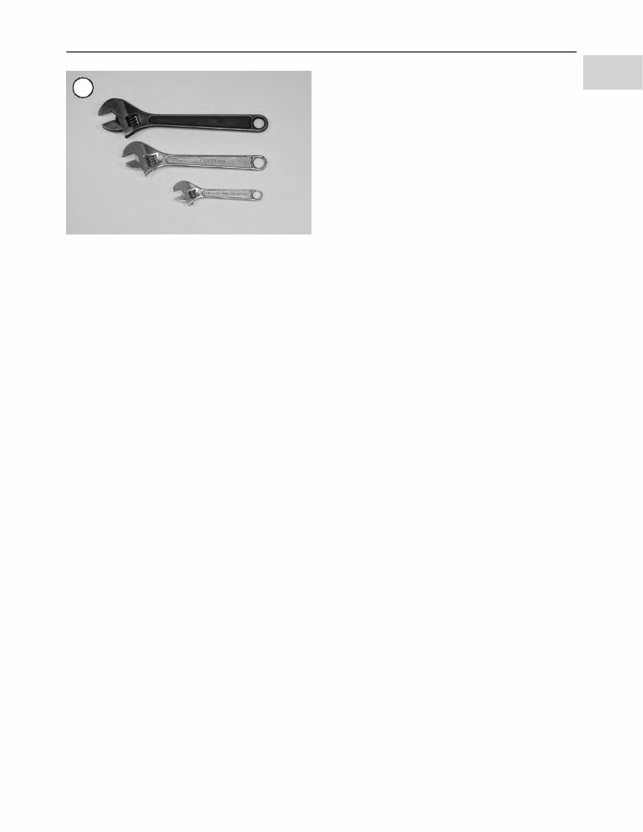
home mechanic. Always use the correct tools for the job at hand. Keep tools organized and clean. Store them in a tool chest with related tools organized together. Quality tools are essential. The best are constructed of high-strength alloy steel. These tools are light, easy to use and resistant to wear. Their working surface is devoid of sharp edges and the tool is carefully polished. They have an easy-to-clean finish and are comfortable to use. Quality tools are a good investment. When purchasing tools to perform the procedures cov- ered in this manual, consider the tool’s potential frequency of use. If starting a new tool kit, consider purchasing a basic tool set from a quality tool supplier. These sets are available in many tool combinations and offer substantial savings when compared to individually purchased tools. As work experience grows and tasks become more complicated, specialized tools can be added. Some of the procedures in this manual specify special tools. Refer to Table 12. In most cases, the tool is illustrated in use. Well-equipped mechanics may be able to substitute similar tools or fabricate a suitable replacement. However, in some cases, the specialized equipment or expertise may make it impractical for the home mechanic to attempt the procedure. When necessary, such operations are identified in the text with the recommendation to have a dealership or specialist perform the task. It may be less expensive to have a professional perform these jobs, especially when consid- ering the cost of the equipment. The manufacturer’s part number is provided for many of the tools mentioned in this manual. These part numbers are correct at the time of original publication. The publisher cannot guarantee the part number or the tools in this manual will be available in the future. Screwdrivers Screwdrivers of various lengths and types are mandatory for the simplest tool kit. The two basic types are the slotted tip (flat blade) and the Phillips tip. These are available in sets that often include an assortment of tip sizes and shaft lengths. As with all tools, use a screwdriver designed for the job. Make sure the size of the tip conforms to the size and shape of the fastener. Use them only for driving screws. Never use a screwdriver for prying or chiseling metal. Repair or re- place worn or damaged screwdrivers. A worn tip may dam- age the fastener, making it difficult to remove. Wrenches Open-end, box-end and combination wrenches (Figure 11) are available in a variety of types and sizes. The number stamped on the wrench refers to the distance between the work areas. This size must match the size of the fastener head. The box-end wrench is an excellent tool because it grips the fastener on all sides. This reduces the chance of the tool slipping. The box-end wrench is designed with either a 6- or 12-point opening. For stubborn or damaged fasteners, the 6-point provides superior holding ability by contacting the fastener across a wider area at all six edges. For general use, the 12-point works well. It allows the wrench to be re- moved and reinstalled without moving the handle over such a wide arc. An open-end wrench is fast and works best in areas with limited overhead access. It contacts the fastener at only two points, and is subject to slipping under heavy force, or if the tool or fastener is worn. A box-end wrench is preferred in most instances, especially when breaking loose and apply- ing the final tightness to a fastener. The combination wrench has a box-end on one end, and an open-end on the other. This combination makes it a very convenient tool. Adjustable Wrenches An adjustable wrench, or Crescent wrench (Figure 12), can fit nearly any nut or bolt head that has clear access around its entire perimeter. Adjustable wrenches are best used as a backup wrench to keep a large nut or bolt from turning while the other end is being loosened or tightened with a box-end or socket wrench. Adjustable wrenches contact the fastener at only two points, which makes them more subject to slipping off the fastener. The fact that one jaw is adjustable and may loosen only aggravates this shortcoming. Make certain the solid jaw is the one transmitting the force. Socket Wrenches, Ratchets and Handles WARNING Do not use hand sockets with air or impact tools, as they may shatter and cause injury. Always wear eye protection when using im- pact or air tools. GENERAL INFORMATION 9 1 12
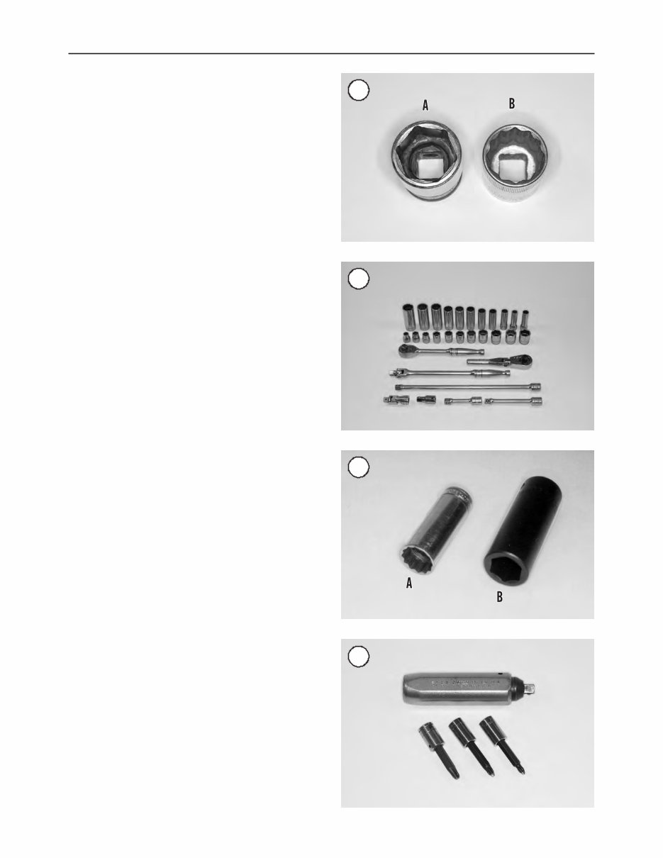
Sockets that attach to a ratchet handle are available with 6-point (A, Figure 13) or 12-point (B) openings and differ- ent drive sizes (Figure 14) . The drive size indicates the size of the square hole that accepts the ratchet handle. The num- ber stamped on the socket is the size of the work area and must match the fastener head. As with wrenches, a 6-point socket provides supe- rior-holding ability, while a 12-point socket needs to be moved only half as far to reposition it on the fastener. Sockets are designated for either hand or impact use. Im- pact sockets are made of thicker material for more durabil- ity. Compare the size and wall thickness of a 19-mm hand socket (A, Figure 15) and the 19-mm impact socket (B). Use impact sockets when using an impact driver or air tools. Use hand sockets with hand-driven attachments. Various handles are available for sockets. The speed han- dle is used for fast operation. Flexible ratchet heads in vary- ing lengths allow the socket to be turned with varying force, and at odd angles. Extension bars allow the socket setup to reach difficult areas. The ratchet is the most versatile. It al- lows the user to install or remove the nut without removing the socket. Sockets combined with any number of drivers make them undoubtedly the fastest, safest and most convenient tool for fastener removal and installation. Impact Driver WARNING Do not use hand sockets with air or impact tools as they may shatter and cause injury. Al- ways wear eye protection when using impact or air tools. An impact driver provides extra force for removing fas- teners, by converting the impact of a hammer into a turning motion. This makes it possible to remove stubborn fasten- ers without damaging them. Impact drivers and inter- changeable bits (Figure 16) are available from most tool suppliers. When using a socket with an impact driver make sure the socket is designed for impact use. Refer to Socket Wrenches, Ratchets and Handles in this section. Allen Wrenches Allen wrenches (Figure 17) are used on fasteners with hexagonal recesses in the fastener head. These wrenches are available in L-shaped bar, socket and T-handle types. Allen bolts are sometimes called socket bolts or setscrews. Torque Wrenches A torque wrench (Figure 18) is used with a socket, torque adapter or similar extension to tighten a fastener to a measured torque. Torque wrenches come in several drive sizes (1/4, 3/8, 1/2 and 3/4) and have various meth- 10 CHAPTER ONE 13 14 15 16
The repair manual for the 1993 Harley Davidson Sportster is designed to cater to the needs of both professional technicians and do-it-yourself mechanics. It provides comprehensive information for individuals with basic knowledge in electrical and mechanical concepts, enabling them to perform maintenance and repairs effectively.
It serves as a valuable reference for maintaining and repairing the vehicle or engine, covering topics typically found in a factory service manual and owner's manual. The manual offers step-by-step guidance, equipping owners with the necessary knowledge to make informed decisions regarding the maintenance and repair of the 1993 Harley Davidson Sportster.
Product Details:
File Format: PDF
Language: English
Specifications: Full Printable
Zoom IN/OUT: YES
Delivery: Instant
Requirements: Adobe Reader & Win
Compatible: All Versions of Windows & Mac
The manual includes step-by-step repair procedures, critical specifications, illustrations, maintenance, disassembly, assembly, cleaning and reinstalling procedures, and more. It offers the same features as a paper manual, with the added convenience of instant access through digital download.
Example of Covered Information:
Engine Removal
Wiring Diagrams
General Information
Specifications
Lube Points
Oil Types
Periodic Maintenance and Tune-Up Procedures
Engine Servicing
Disassembly and Reassembly
Fuel and Lubrication Systems
Electrical System
Chassis, Steering, and Suspension
Brakes and Wheels
Service Data and Tools
Complete Engine Service
Fuel System Service
Factory Repair Procedures
Exhaust System
Fault Finding
Transmission and Gearbox Service
Cooling System
Detailed Specifications
Factory Maintenance Schedules
Electrics and More
Recently Viewed
5,521,897Happy Clients
2,594,462eManuals
1,120,453Trusted Sellers
15Years in Business
Price:
Actual Price:
1993 Harley-Davidson Sportster Service & Repair Manual