1 2 3 4 5 6 7 8 9 10 11 12 13 14 15 16 17 Chapter One General Information Chapter Two Troubleshooting Chapter Three Periodic Lubrication, Maintenance & Tune-up Chapter Four Engine Chapter Five Clutch, Primary Drive & Starter Drive Chapter Six 4-Speed Transmission Chapter Seven 5-Speed Transmission Chapter Eight Fuel, Exhaust & Emission Control Systems Chapter Nine Electrical System Chapter Ten Wheels, Hubs & Tires Chapter Eleven Front Suspension & Steering Chapter Twelve Rear Suspension Chapter Thirteen Brakes Chapter Fourteen Cruise Control Chapter Fifteen Body Index Wiring Diagrams
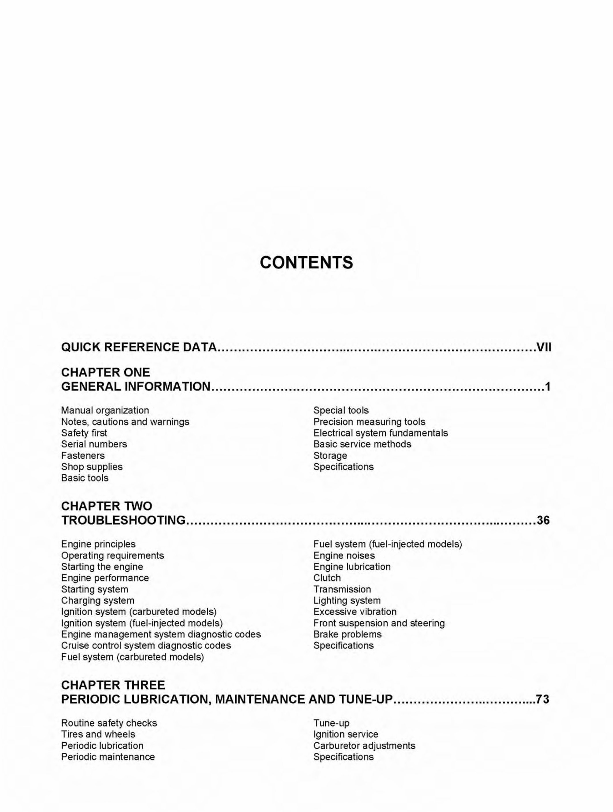
CONTENTS QUICK REFERENCE DATA ............................................................................... VII CHAPTER ONE GENERAL INFORMATION .................................................................................. 1 Manual organization Notes, cautions and warnings Safety first Serial numbers Fasteners Shop supplies Basic tools CHAPTER TWO Special tools Precision measuring tools Electrical system fundamentals Basic service methods Storage Specifications TROUBLES HOO Tl NG .......................................... ............................................. 36 Engine principles Operating requirements Starting the engine Engine performance Starting system Charging system Ignition system (carbureted models) Ignition system (fuel-injected models) Engine management system diagnostic codes Cruise control system diagnostic codes Fuel system (carbureted models) CHAPTER THREE Fuel system (fuel-injected models) Engine noises Engine lubrication Clutch Transmission Lighting system Excessive vibration Front suspension and steering Brake problems Specifications PERIODIC LUBRICATION, MAINTENANCE AND TUNE-UP ............................... ..... 73 Routine safety checks Tires and wheels Periodic lubrication Periodic maintenance Tune-up Ignition service Carburetor adjustments Specifications
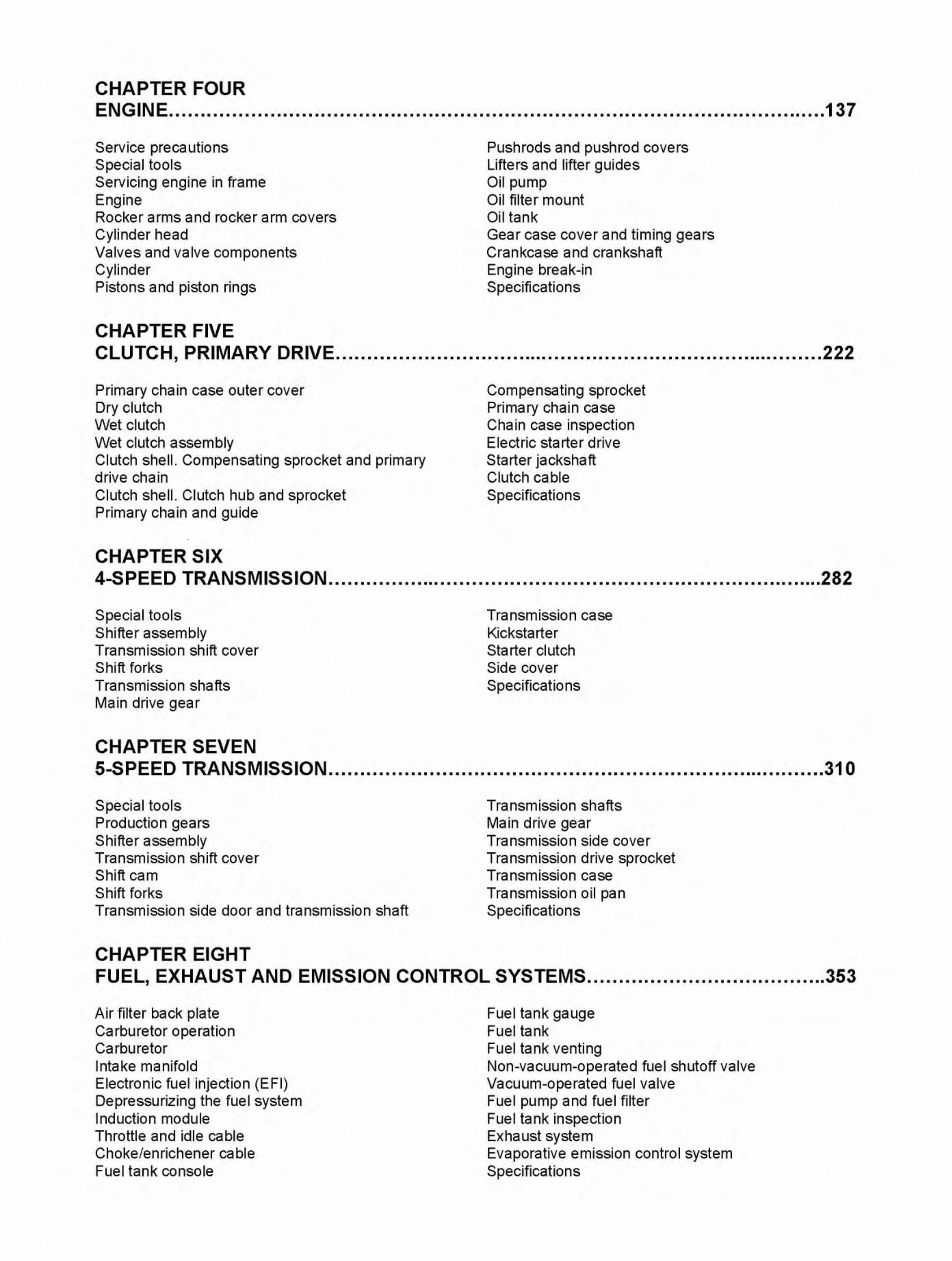
CHAPTER FOUR ENGINE ........................................................................................................ 137 Service precautions Special tools Servicing engine in frame Engine Rocker arms and rocker arm covers Cylinder head Valvesandvalvecomponen~ Cylinder Pistons and piston rings CHAPTER FIVE Pushrods and pushrod covers Lifters and lifter guides Oil pump Oil filter mount Oil tank Gear case cover and timing gears Crankcase and crankshaft Engine break-in Specifications CLUTCH, PRIMARY DRIVE .............................................................................. 222 Primary chain case outer cover Dry clutch Wet clutch Wet clutch assembly Clutch shell. Compensating sprocket and primary dr ive chain Clutch shell. Clutch hub and sprocket Primary chain and guide CHAPTER SIX Compensating sprocket Primary chain case Chain case inspection Electric starter drive Starter jackshaft Clutch cable Specifications 4-SPEED TRANSMISSION ............................................................................... 282 Special tools Shifter assembly Transmission shift cover Shift forks Transmission shafts Main drive gear CHAPTER SEVEN Transmission case Kickstarter Starter clutch Side cover Specifications 5-SPEED TRANSMISSION ............................................................................... 31 0 Special tools Production gears Shifter assembly Transmission shift cover Shift cam Shift forks Transmission side door and transmission shaft CHAPTER EIGHT Transmission shafts Main drive gear Transmission side cover Transmission drive sprocket Transmission case Transmission oil pan Specifications FUEL, EXHAUST AND EMISSION CONTROL SYSTEMS ...................................... 353 Air filter back plate Carburetor operation Carburetor Intake manifold Electronic fuel injection (E Fl) Depressurizing the fuel system Induction module Throttle and idle cable Choke/enrichener cable Fuel tank console Fuel tank gauge Fuel tank Fuel tank venting Non-vacuum-operated fuel shutoff val ve Vacuum-operated fuel valve Fuel pump and fuel filter Fuel tank inspection Exhaust system Evaporative emission control system Specifications
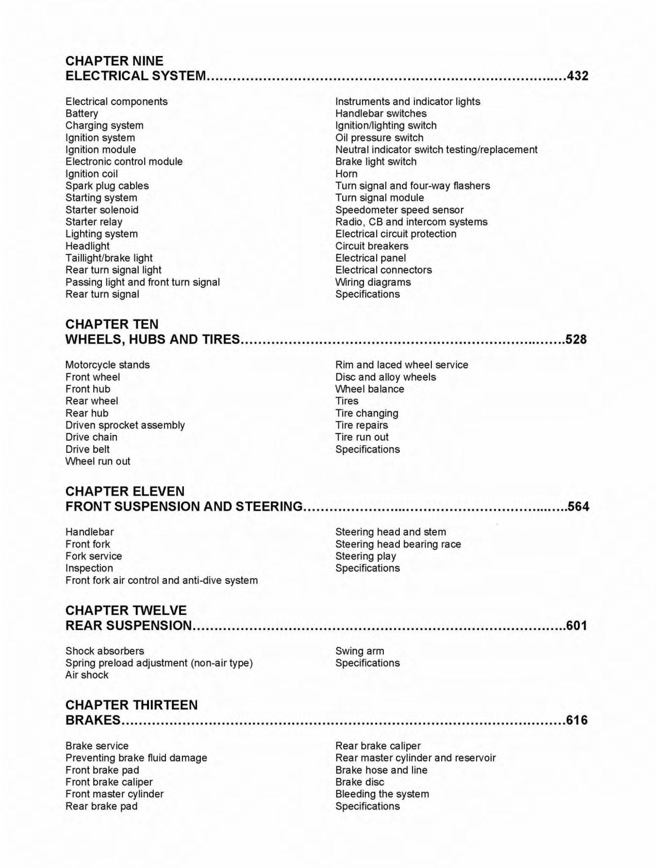
CHAPTER NINE ELECTRICAL SYSTEM ................................................................................... 432 Electrical components Battery Charging system Ignition system Ignition module Electronic control module Ignition coil Spark plug cables Starting system Starter solenoid Starter relay Lighting system Headlight Taillight/brake light Rear turn signal light Passing light and front turn signal Rear turn signal CHAPTER TEN Instruments and indicator lights Handlebar switches Ignition/lighting switch Oil pressure switch Neutral indicator switch testing/replacement Brake light switch Horn Turn signal and four-way flashers Turn signal module Speedometer speed sensor Radio, CB and intercom systems Electrical circuit protection Circuit breakers Electrical panel Electrical connectors Wiring diagrams Specifications WHEELS, HUBS AND TIRES ........................................................................... 528 Motorcycle stands Front wheel Front hub Rear wheel Rear hub Driven sprocket assembly Drive chain Drive belt Wheel run out CHAPTER ELEVEN Rim and laced wheel service Disc and alloy wheels V\lheel balance Tires Tire changing Tire repairs Tire run out Specifications FRONT SUSPENSION AND STEERING .............................................................. 564 Handlebar Front fork Fork service Inspection Front fork air control and anti-dive system CHAPTER TWELVE Steering head and stem Steering head bearing race Steering play Specifications REAR SUSPENSION ...................................................................................... 601 Shock absorbers Spring preload adjustment (non-a ir type) Air shock CHAPTER THIRTEEN Swing arm Specifications BRAKES ...................................................................................................... 616 Brake service Preventing brake fluid damage Front brake pad Front brake caliper Front master cylinder Rear brake pad Rear brake caliper Rear master cylinder and reservoir Brake hose and line Brake disc Bleeding the system Specifications
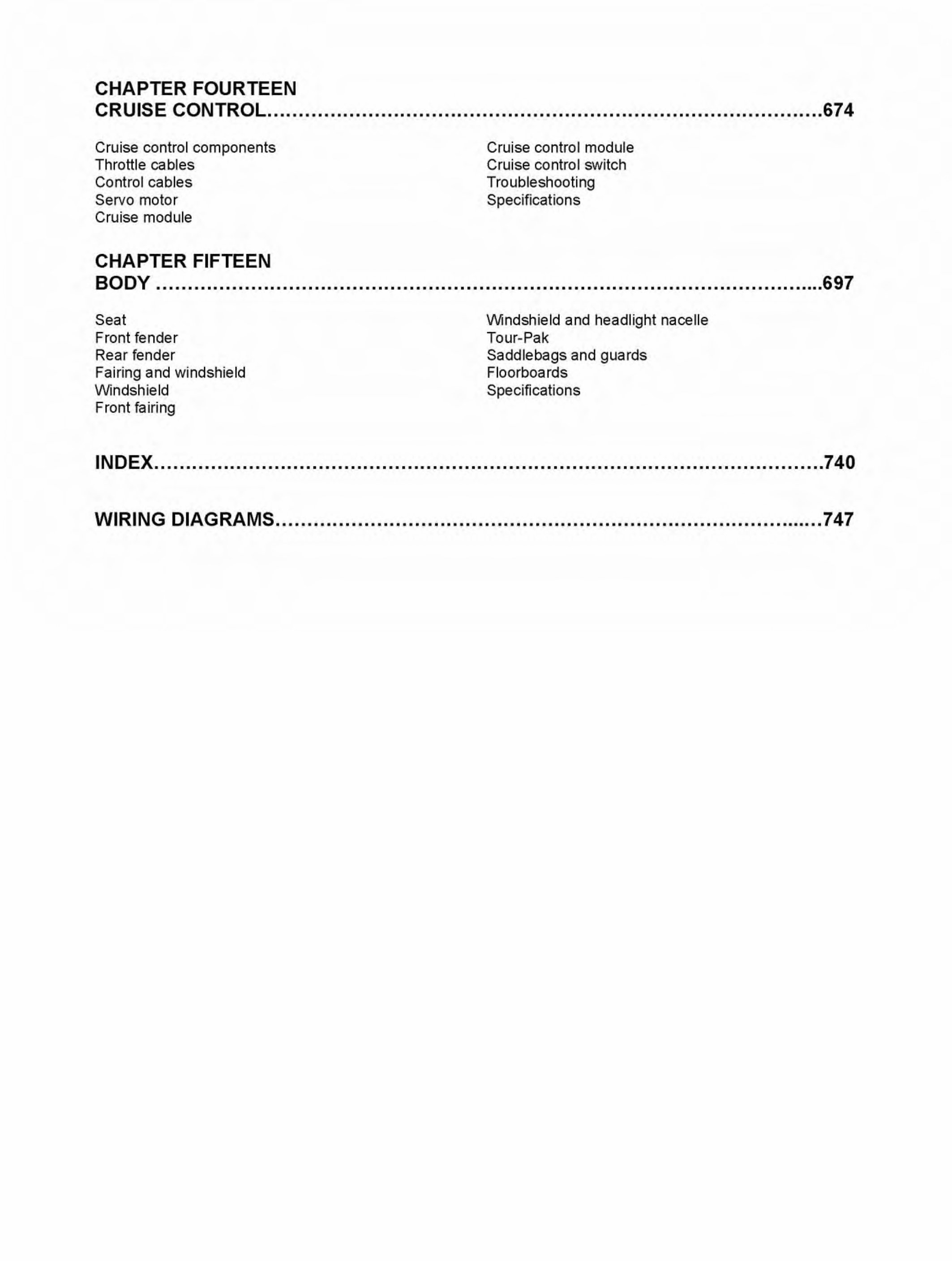
CHAPTER FOURTEEN CRUISE CONTROL ........................................................................................ 674 Cruise control components Throttle cables Control cables Servo motor Cruise module CHAPTER FIFTEEN Cruise control module Cruise control switch Troubleshooting Specifications BODY .......................................................................................................... 697 Seat Front fender Rear fender Fairing and windshield Windshield Front fairing Windshield and headlight nacelle Tour-Pak Saddlebags and guards Floorboards Specifications INDEX .......................................................................................................... 740 WIRING DIAGRAMS ....................................................................................... 747
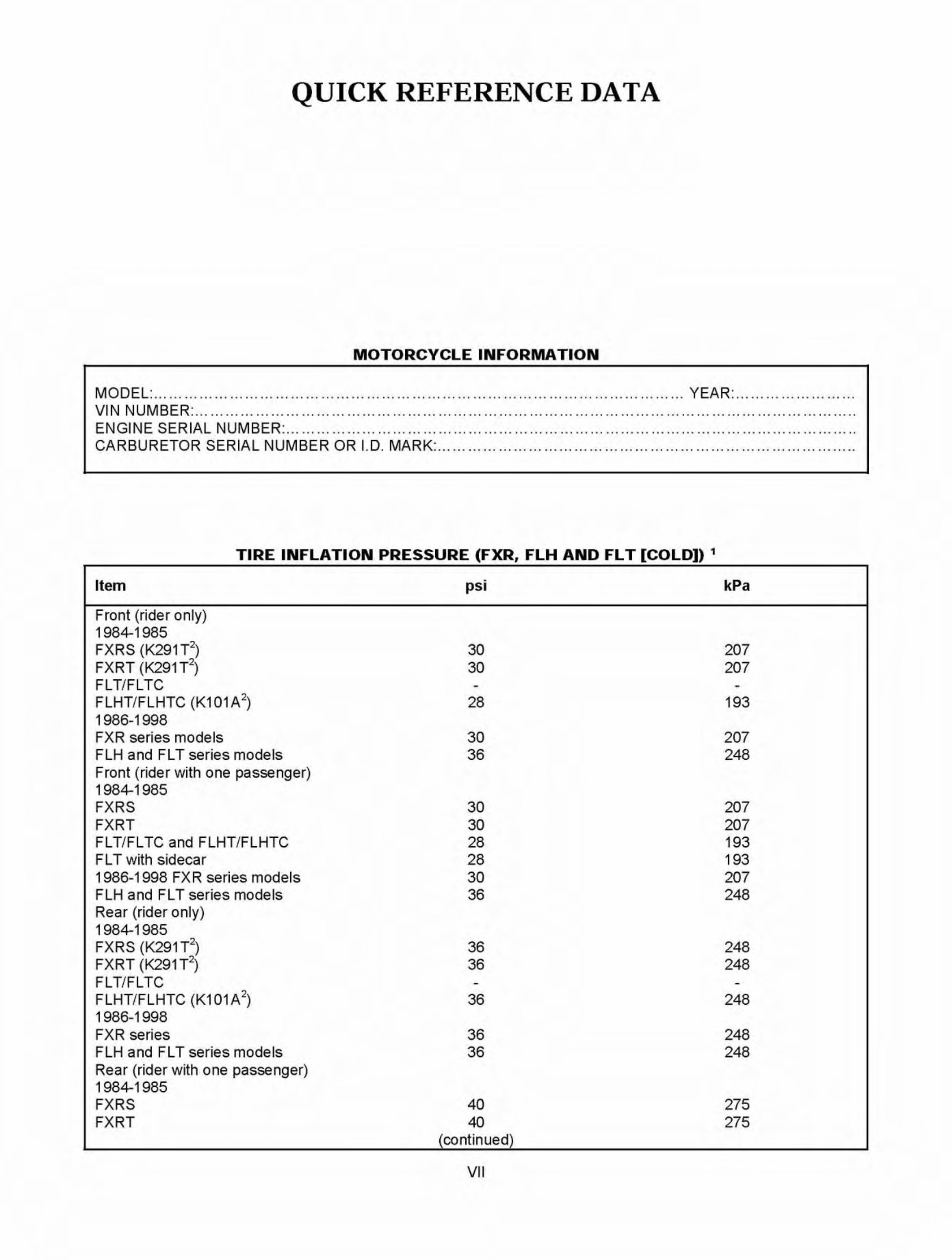
QUICK REFERENCE DATA MOTORCYCLE INFORMATION MODEL : .. . .. ... .......... . .. . ....... . .. ... .......... .... ....... . ............... . .. . ....... . .. ... .......... ...... YEAR: ....... ... .. . ....... . .. . VIN NUMBER: .......... ... .. ... .. ... . .. . .. ....... .... .. ... . .... . .. . .. ... .. ...... .. ... .. ... . .. . .. ....... .... .. ... . .... . .. . .. ... .. ...... .. ... .. .. . ENGINE SERIAL NUMBER: ................................................................................................................ . CARBURETOR SERIAL NUMBER OR I. D. MARK: ....... .. ...... .. . .. ..... .. ....... .. . .. ...... .. . .. .. .. ....... .. ...... .. . .. ..... .. .. TIRE INFLATION PRESSURE (FXR, FLH AND FL T [COLD]) 1 Item Front (rider only) 1984-1985 FXRS (K291 T 2 ) FXRT (K291 T 2 ) FLT/FLTC FLHT/FLHTC (K101A 2 ) 1986-1998 FXR series models FLH and FLT series models Front (rider with one passenger) 1984-1985 FXRS FXRT FL T/FL TC and FLHT/FLHTC FL T with sidecar 1986-1998 FXR series models FLH and FLT series models Rear (r id er only) 1984-1985 FXRS (K291 T 2 ) FXRT (K291 T 2 ) FLT/FLTC FLHT/FLHTC (K 1 01 A 2 ) 1986-1998 FXR series FLH and FL T series models Rear (rider with one passenger) 1984-1985 FXRS FXRT pst 30 30 28 30 36 30 30 28 28 30 36 36 36 36 36 36 40 40 (continued) VII kPa 207 207 193 207 248 207 207 193 193 207 248 248 248 248 248 248 275 275
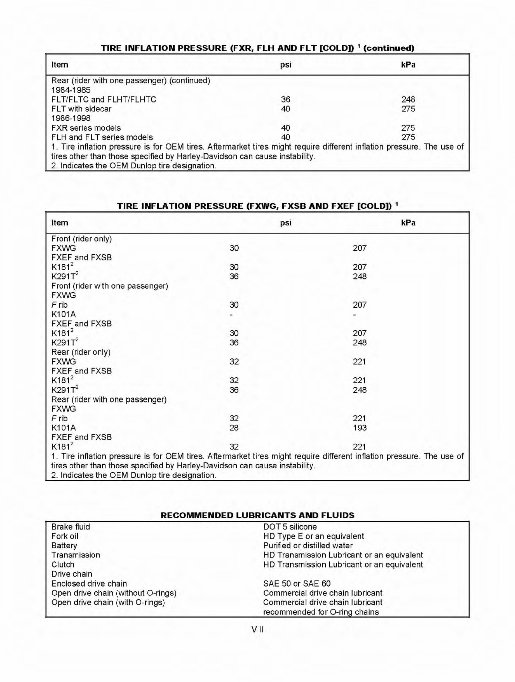
TIRE INFLATION PRESSURE (FXR, FLH AND FLT [COLD]) 1 (continued) Item Rear (rider with one passenger) (continued) 1984-1985 FL T/FL TC and FLHT/FLHTC FLT with sidecar 1986-1998 pst 36 40 kPa 248 275 FXR series models 40 275 FLH and FLT series models 40 275 1. Tire inflation pressure is for OEM tires. Aftermarket tires might require different inflation pressure. The use of tires other than those specified by Harley-Davidson can cause instability. 2. Indicates the OEM Dunlop tire designation. TIRE INFLATION PRESSURE (FXWG, FXSB AND FXEF [COLD]) 1 Item Front (rider only) FXWG FXEF and FXSB K181 2 K291T 2 Front (rider with one passenger) FXWG F rib K101A FXEF and FXSB K181 2 K291T 2 Rear (rider only) FXWG FXEF and FXSB K181 2 K291T 2 Rear (rider with one passenger) FXWG F rib K101A FXEF and FXSB K181 2 30 30 36 30 30 36 32 32 36 32 28 32 . pst 207 207 248 207 207 248 22 1 221 248 221 193 221 kPa 1. Tire inflation pressure is for OEM tires. Aftermarket tires might require different inflation pressure. The use of tires other than those specified by Harley-Davidson can cause instability. 2. Indicates the OEM Dunlop tire designation. RECOMMENDED LUBRICANTS AND FLUIDS Brake fluid Fork oi l Battery Transmission Clutch Drive chain Enclosed drive chain Open drive chain (without 0-r ings) Open drive chain (with 0-rings) DOT 5 silicone HD Type E or an equival ent Purified or distilled water HD Transmission Lubricant or an equivalent HD Transmission Lubricant or an equivalent SAE 50 or SAE 60 Commercial drive chain lubricant Commercial drive chain lubricant recommended for 0-ring chains V II I
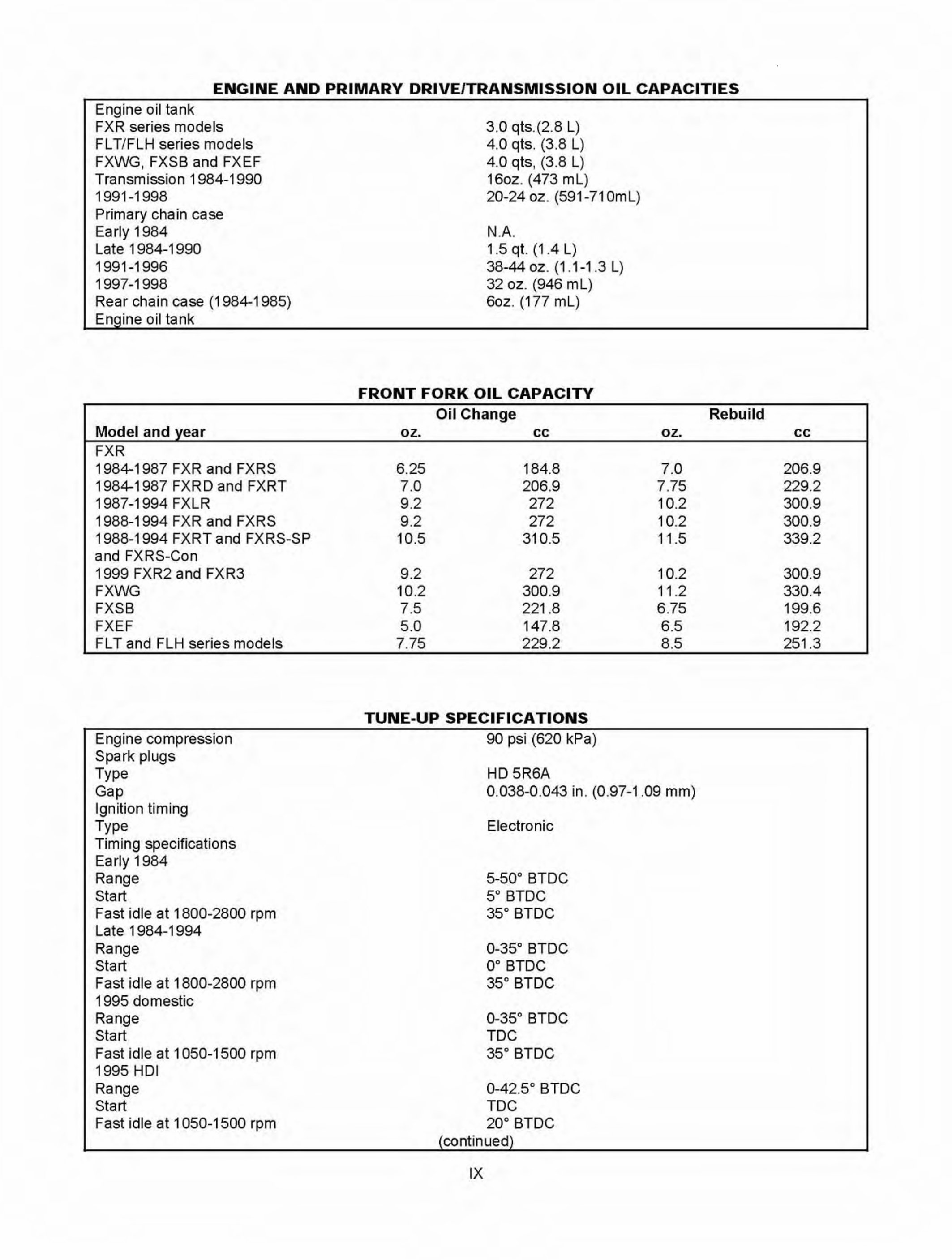
ENGINE AND PRIMARY DRIVE/TRANSMISSION OIL CAPACITIES Engine oil tank FXR series models FL T/FLH series models FXWG, FXSB and FXEF Transmission 1984-1990 1991-1998 Primary chain case Early 1984 Late 1 984-1990 1991-1996 1997-1998 Rear chain case (1984-1985) Engine oil tank Model and year FXR 1984-1987 FXR and FXRS 1984-1987 FXRD and FXRT 1987-1994 FXLR 1988-1994 FXR and FXRS 1988-1994 FXRT and FXRS-SP and FXRS-Con 1999 FXR2 and FXR3 FXWG FXSB FXEF FLT and FLH series models Engine compression Spark plugs Type Gap Ignition timing Type Timing specifications Early 1984 Range Start Fast idle at 1800-2800 rpm Late 1 984-1994 Range Start Fast idle at 1800-2800 rpm 1995 domestic Range Start Fast idle at 1 050-1500 rpm 1995 HOI Range Start Fast idle at 1 050-1500 rpm 3.0 qts.(2.8 L) 4.0 qts. (3.8 L) 4.0 qts , (3.8 L) 16oz. (473 mL) 20-24 oz. (591-71 OmL) N. A. 1.5 qt. (1 .4 L) 38-44 oz. (1 .1-1.3 L) 32 oz . (946 mL) 6oz. (177 mL) FRONT FORK OIL CAPACITY Oil Change oz. cc 6.25 184.8 7.0 206 .9 9.2 272 9.2 272 10.5 310.5 9.2 272 10.2 300 .9 7.5 221.8 5.0 147.8 7.75 229 .2 TUNE-UP SPECIFICATIONS 90 psi (620 kPa) HD 5R6A oz. 7.0 7. 75 10 .2 10 .2 11.5 10 .2 11 .2 6.75 6.5 8 .5 0.038-0. 043 in. (0.97-1.09 mm) Electronic 5-50° BTDC 5o BTDC 35° BTDC 0-35° BTDC oo BTDC 35° BTDC 0-35° BTDC TDC 35° BTDC 0-42.5° BTDC TDC 20° BTDC (continued) IX Rebuild cc 206.9 229.2 300.9 300.9 339.2 300.9 330.4 199.6 192.2 251.3
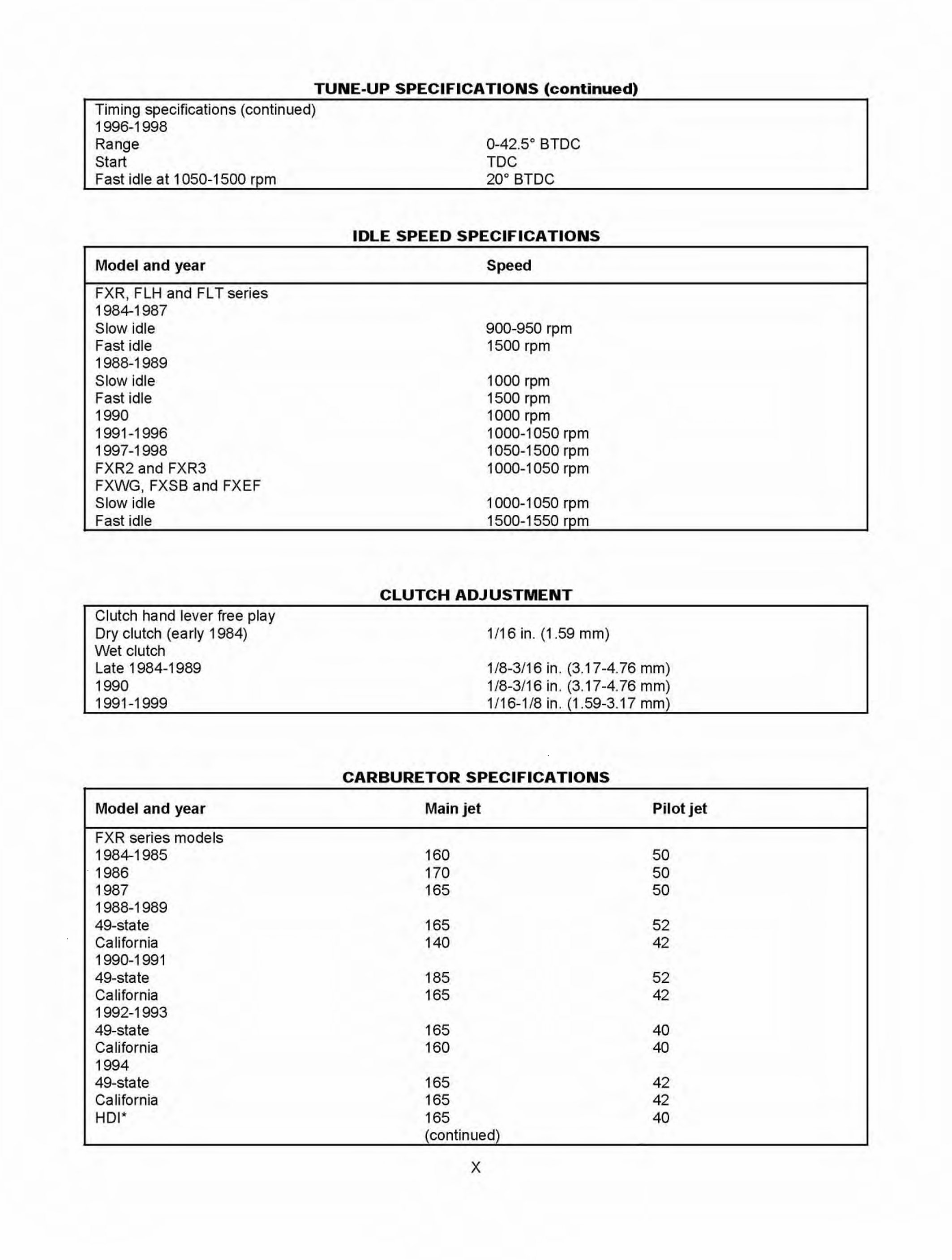
TUNE-UP SPECIFICATIONS (continued) Timing specifications (continued) 1996-1998 Range Start Fast idle at 1 050-1500 rpm Model and year FXR, FLH and FLT series 1984-1987 Slow idle Fast idle 1988-1989 Slow idle Fast idle 1990 1991-1996 1997-1998 FXR2 and FXR3 FXWG, FXSB and FXEF Slow idle Fast idle Clutch hand lever free play Dry clutch (early 1984) Wet clutch Late 1 984-1989 1990 1991-1999 Model and year FXR series models 1984-1985 1986 1987 1988-1989 49-state California 1990-1991 49-state California 1992-1993 49-state California 1994 49-state California HOI* 0-42.5° BTDC TDC 20° BTDC IDLE SPEED SPECIFICATIONS Speed 900-950 rpm 1500 rpm 1000 rpm 1500 rpm 1000 rpm 1000-1 050 rpm 1 050-1500 rpm 1000-1050 rpm 1000-1050 rpm 1500-1550 rpm CLUTCH ADJUSTMENT 1/16 in. (1.59 mm) 1/8-3/16 in. (3.17-4.76 mm) 1/8-3/16 in. (3.1 7-4. 76 mm) 1/16-1/8 in. (1.59-3.17 mm) CARBURETOR SPECIFICATIONS Main jet Pilot jet 160 50 170 50 165 50 165 52 140 42 185 52 165 42 165 40 160 40 165 42 165 42 165 40 (continued) X
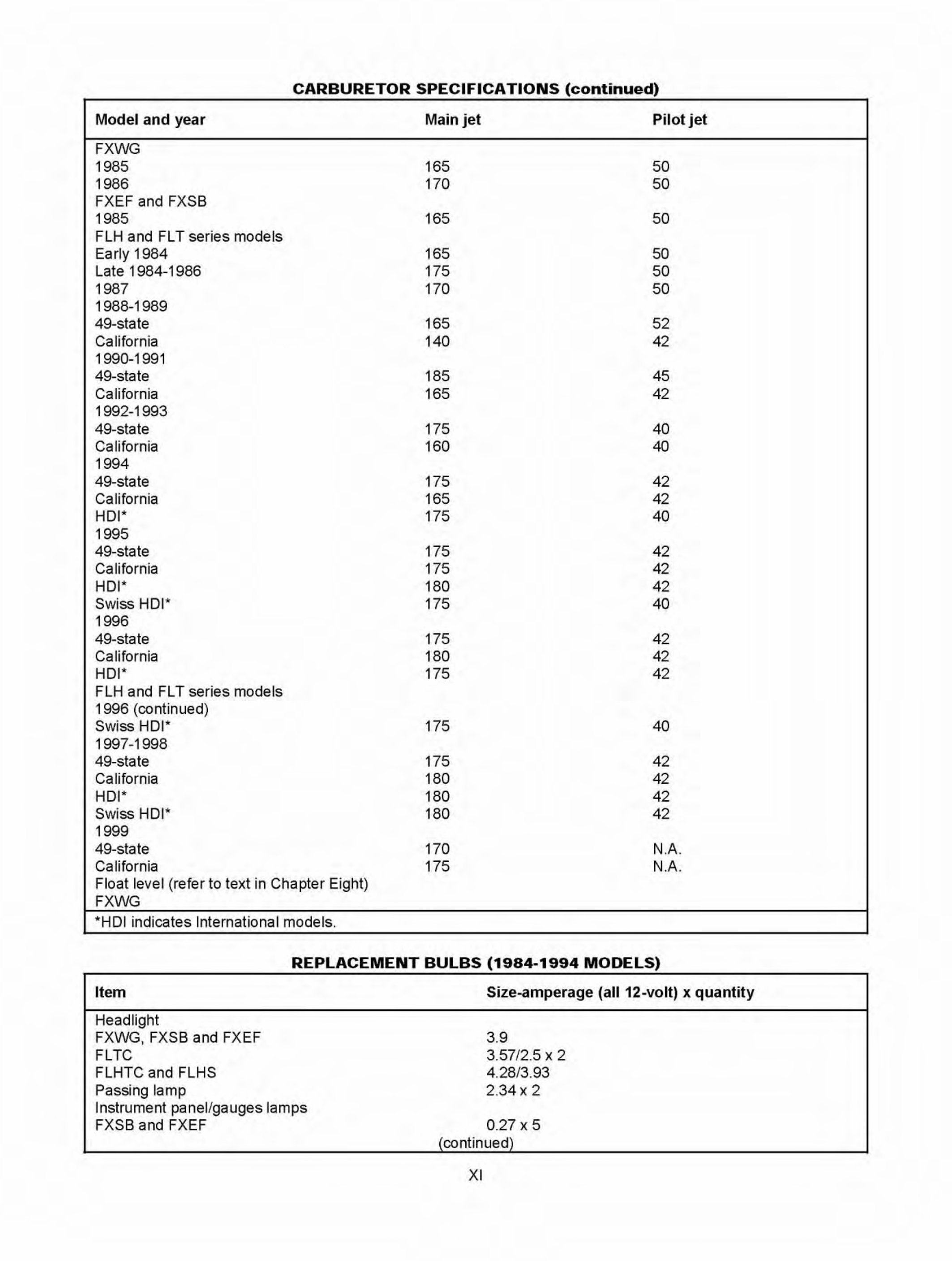
CARBURETOR SPECIFICATIONS (continued) Model and year Main jet Pilot jet FXWG 1985 165 50 1986 170 50 FXEF and FXSB 1985 165 50 FLH and FL T series models Early 1984 165 50 Late 1 984-1986 175 50 1987 170 50 1988-1989 49-state 165 52 California 140 42 1990-1991 49-state 185 45 California 165 42 1992-1993 49-state 175 40 California 160 40 1994 49-state 175 42 California 165 42 HOI* 175 40 1995 49-state 175 42 California 175 42 HOI* 180 42 Swiss HOI* 175 40 1996 49-state 175 42 California 180 42 HOI* 175 42 FLH and FLT series models 1996 (continued) Swiss HOI* 175 40 1997-1998 49-state 175 42 California 180 42 HOI* 180 42 Swiss HOI* 180 42 1999 49-state 170 N.A. California 175 N.A. Float level (ref er to text in Chapter Eight) FXWG *HOI in dicates International models. REPLACEMENT BULBS (1984-1994 MODELS) Item Headlight FXWG, FXSB and FXEF FLTC FLHTC and FLHS Passing lamp Instrument panel/gauges lamps FXSB and FXEF Size-amperage (all 12-volt) x quantity 3.9 3.57/2.5 X 2 4.28/3. 93 2.34 X 2 0.27 X 5 (continued) XI
Fixing problems on your bike is a Do-It-Yourself approach with this motorcycle repair manual as it contains every troubleshooting and replacement procedure provided by the manufacturer, including step-by-step instructions, clear images, and exploded-view illustrations.
The durability of your motorcycle is unquestionable, but you also know that no matter how tough it is, regular maintenance is definitely required. And even when properly maintained, with time, some parts will eventually wear out and will need to be replaced.
Luckily, that's where a good motorcycle repair manual will come in handy, providing you with the manufacturer's recommended troubleshooting charts and replacement procedures; basically, everything you need to fix your ride. As a result, you’ll be able to save on repairs, increase your bike’s reliability, and keep the repair shop at bay — what’s not to like, right?
Please note:
This is not a generic repair manual. This is the repair manual used by professional technicians to service and maintain your motorcycle. The manual contains every troubleshooting and replacement procedure provided by the manufacturer, including step-by-step instructions, exploded-view illustrations, and clear images.
No need to flip through hundreds of pages to find specific information; no more greasy, torn, or lost pages anymore! Carry them around, search them, screenshot them, bookmark them — much better than a traditional bound manual if you ask me.
Of course, if you prefer to have a physical copy, nothing prevents you from printing it out too.
Printable: Yes Language: English Compatibility: Pretty much any electronic device, incl. PC & Mac computers, Android and Apple smartphones & tablet, etc. Requirements: Adobe Reader (free)