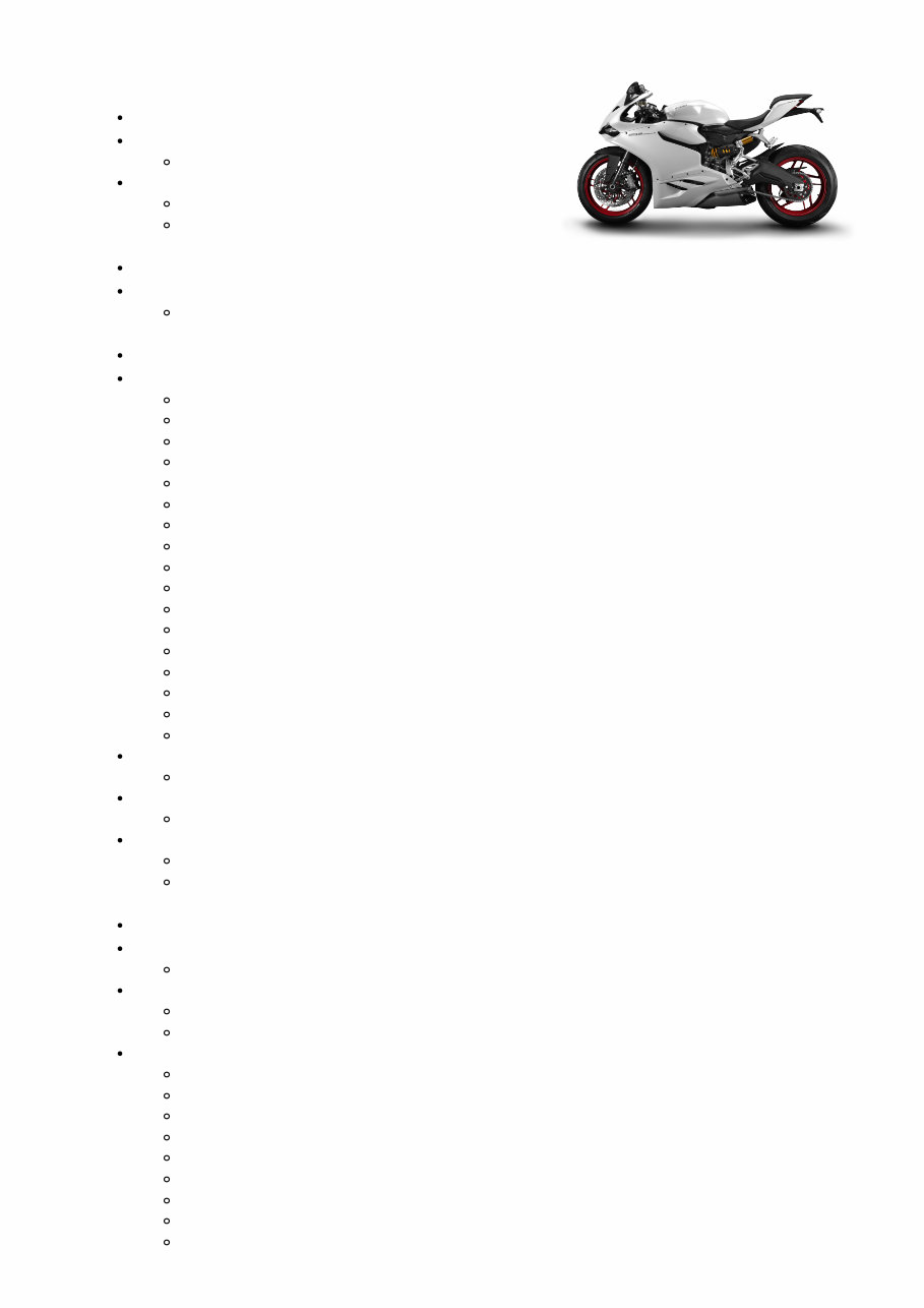
2014-2015 Ducati 899 Panigale Service & Repair Manual
What's Included?
Lifetime Access
Fast Download Speeds
Offline Viewing
Access Contents & Bookmarks
Full Search Facility
Print one or all pages of your manual
DUCATI 899 Panigale 2014 Workshop Manual SBK.01 - General Symbols - Abbreviations - References Product specifications Hazardous Products - Warnings General maintenance instructions General safety rules SBK.02 - Information about the model Identification data Identification data SBK.03 - Technical data Technical specifications Lights/instrument panel Injection system Fuel system Injection-ignition system Charging system/alternator Hydraulic brakes Rear suspension Rear wheel Front suspension Front wheel Gearbox Cylinder/Piston Crankshaft Timing system/valves Transmission Colours General Dimensions Dimensions Fuel, lubricants and other fluids Fuel, lubricants and other fluids Torque settings Engine torque settings Frame torque settings SBK.04 - Maintenance operations Vehicle pre-delivery Vehicle pre-delivery Scheduled maintenance chart Operations to be carried out by the customer Operations to be carried out by the dealer Maintenance operations Adjusting the rear shock absorber Adjusting the front fork Adjusting the position of the gear change and rear brake pedals Adjusting the clutch lever and front brake lever Checking the rear brake pad wear and changing the brake pads Checking the front brake pad wear and changing the brake pads Adjusting the chain tension Adjusting the steering head bearing play Filling the clutch circuit
Draining the clutch hydraulic circuit Changing the clutch fluid Changing the fluid in the rear brake system Changing the fluid in the front brake system Changing the coolant Checking the coolant level Changing and cleaning the air filters Spark plugs replacement Checking valve clearance Changing the engine oil and filter cartridge Check engine oil level SBK.05 - Fairings Rear-view mirrors Refitting the rear-view mirrors Removal of the rear-view mirrors Headlight fairing Refitting the headlight fairing Removing the headlight fairing Fairing panels Refitting the side fairings Removal of the side fairings Seat - seat cowling and side panels Refitting the seat release mechanism Removal of the seat release mechanism Refitting the side panels Removal of the side panels Refitting the rider seat Removal of the rider seat Refitting the pillion seat Removal of the pillion seat Front and rear mudguard Refitting the rear mudguard Removing the rear mudguard Refitting the front mudguard Removing the front mudguard SBK.06 - Electric system and engine control system Wiring diagram Table V Table T Table S Table R Table Q Table P Table O Table N Table L Table K Table J Table I Table H Table G Table F Table D Table C Table B
Table A Routing of wiring on frame Key to wiring diagram Battery charging system Rectifier-regulator Alternator Battery Topping up the electrolyte Recharging the battery Checking the battery charging system Electric starting system Solenoid starter Starter motor Electric starting system Lights and indicating devices Headlight aim Renewal of the headlight Indicating devices Checking the indicating devices Protection and safety devices Checking the fuses SBK.07 - Chassis Front wheel Refitting the front wheel Overhauling the front wheel Removing the front wheel Rear wheel Refitting the rear wheel Overhauling the rear wheel Removing of the rear wheel Front brake control Overhauling the front brake components Removing the front brake master cylinder Refitting the front brake system Refitting the brake discs Overhauling the front brake components Removing the brake discs Removing the front brake system Refitting the front brake master cylinder Removing the front brake master cylinder Rear brake Refitting the rear brake calliper Removing the rear brake calliper Refitting the rear brake control Removing the rear brake control ABS system components Wiring/hose routing Refitting the ABS control unit Removing the ABS control unit Handlebar unit: throttle twistgrip Refitting the throttle twistgrip Removal of the throttle twistgrip Handlebar unit: hydraulic clutch control Refitting the clutch transmission unit Removal of the clutch transmission unit Steering damper
Refitting the steering damper Removal of the steering damper Gearchange mechanism Refitting the gearchange mechanism Removing the gearchange mechanism Fork - steering head: front fork Overhauling the front forks Refitting the front forks Removal of the front forks Rear shock absorber assembly Refitting the shock absorber support Removal of the shock absorber support Refitting the rear suspension Removal of the rear shock absorber Swingarm Refitting the rear swinging arm Overhauling the rear swinging arm Removing the swinging arm Final drive Lubricating the chain Washing the chain Refitting the rear sprocket Replacing of the rear sprocket Refitting the front sprocket Removing of the front sprocket Inspecting the final drive Footrest brackets Reassembling the front footrest brackets Removing the front footrest brackets Refitting the front footrests Removal of the front footrests Stands Refitting the side stand Removing of the side stand Frame inspection Reassembling the frame and the lateral footrests Removing the frame and the lateral footrests Reassembly of the tool tray Removal of the tool tray Reassembly of structural components and the frame Checking the frame Disassembly of structural components and the frame Tail light - number plate holder Refitting the tail light Removal of the tail light Refitting the number plate holder Removing the number plate holder SBK.08 - Fuel/Exhaust System Fuel tank Replacing the tank flange and fuel sensor. Refitting the fuel tank Refitting the filler cap Removal of the fuel tank filler cap Removal of the fuel tank Airbox - Throttle Body Refitting airbox and throttle body
Removing the airbox and throttle body Air intake Refitting the air filters Removing the air filters Exhaust system Refitting the silencer Refitting the exhaust system Removing the exhaust system Removing the silencer Evaporative emissions canister Refitting the Canister filter Removing the Canister filter Canister filter system SBK.09 - Engine Cooling system: radiator Removal of the radiator Refitting of the cooling system hoses and unions Removing the cooling system hoses and unions Refitting of the radiator Replacing the cooling fan Removal of the radiator Flywheel - alternator Removal of the flywheel/alternator assembly Fitting of the alternator-side crankcase cover Fitting of the flywheel-alternator assembly Overhaul of the flywheel/alternator assembly Disassembly of the generator cover Removal of the generator cover Clutch assembly: clutch Refitting of the clutch Checks and overhaul of the components Removing the clutch Description of the clutch assembly Clutch assembly: clutch cover Refitting of the clutch cover Reassembly of the clutch-side crankcase cover Disassembly of the clutch cover Removal of the clutch cover Clutch assembly: primary drive gears Refitting of the primary drive gears and checking backlash Removing the primary drive gears Cooling system: water pump Refitting of the water pump Removal of the water pump Lubrication system: oil delivery pump Reassembly of the oil delivery pump Disassembly of the oil delivery pump Refitting of the oil delivery pump Removal of the oil delivery pump Lubrication system: oil heat exchanger Refitting of the oil heat exchanger Removal of the oil heat exchanger Gearbox assembly: gearchange mechanism Refitting of the gear selector lever Removing the gearchange mechanism Cylinder head assemblies: checks and adjustments
Checking the engine timing Checking and adjusting the valve clearance Cylinder head assemblies: camshafts Check of the camshafts and supports Positioning crankshaft at power stroke TDC Refitting of the camshafts Removal of the camshafts Cylinder head assemblies: rocker arms Removal of the rocker arms Cylinder head assemblies: timing system Refitting of the heads (from removal of the heads with timing chain removal) Removal of the heads with timing chain removal Refitting of the heads (from removal of the heads without removing the timing chain) Removal of the heads without removing the timing chain Refitting of the chain Removing of the chain Cylinder head assemblies: valves Overhaul of the head components Refitting of the valves Removing the valve rocker arms Sleeve-piston set Overhaul of the sleeve-piston set components Crankcase assembly: external components Refitting of the external components Removing outer components Crankcase assembly: crankcase halves Overhaul of the crankcase halves Reassembly of the crankcase halves Refitting of the crankcase halves Crankshaft main bearings Separation of the crankcase halves Crankcase assembly: connecting rods Refitting the connecting rod assembly Reassembly of the connecting rods Overhaul of the connecting rods Disassembling the connecting rod assembly Removal of the crankshaft/connecting rods assembly Lubrication system: scavenge oil pump Refitting of the scavenge oil pump Removal of the scavenge oil pump Gearbox assembly: gearbox shafts Reassembling the gearbox shafts Inspecting the fork selector drum Inspecting the gear selector forks Overhauling the gearbox Disassembling the gearbox shafts Refitting of the gearbox Removing the gearbox assembly
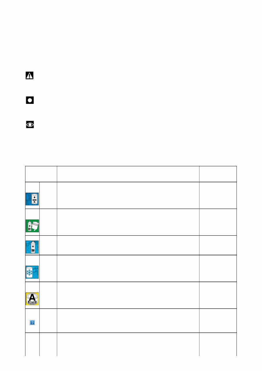
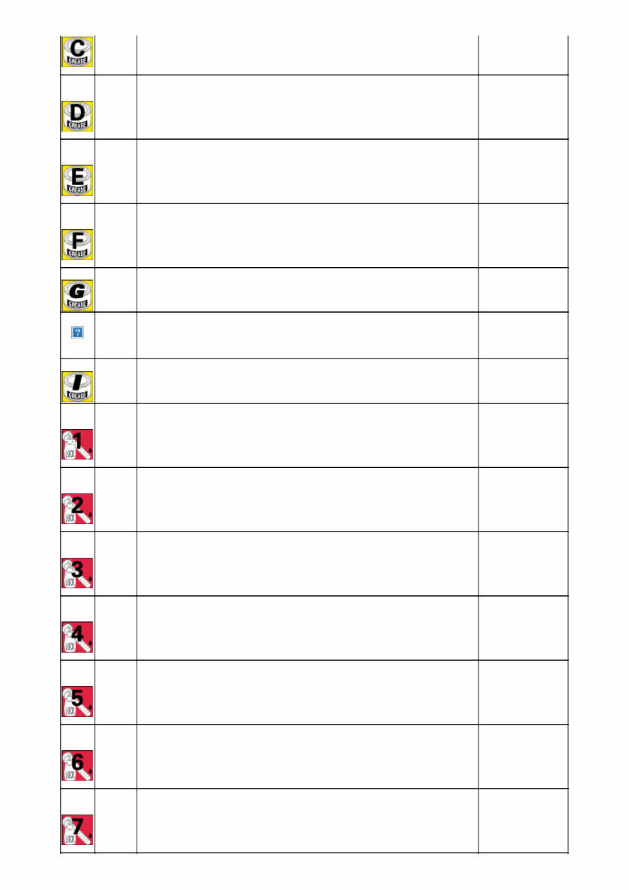
Symbols - Abbreviations - References To allow quick and easy consultation, this manual uses graphic symbols to highlight situations in which maximum care is required, as well as practical advice or information. Pay attention to the meaning of the symbols since they serve to avoid repeating technical concepts or safety warnings throughout the text. The symbols should therefore be seen as real "reminders". Please refer to this page whenever in doubt as to their meaning. The terms right-hand and left-hand refer to the motorcycle viewed from the riding position. Warning Failure to comply with these instructions may put you at risk, and could lead to severe injury or even death. Important Failure to follow the instructions in text marked with this symbol can lead to serious damage to the motorcycle and its components. Note This symbol indicates additional useful information for the current operation. Product specifications Symbols in the diagram show the type of threadlocker, sealant or lubricant to be used at the points indicated. The table below shows the symbols used and the specifications of the various products. Symbol Specifications Recommended product Engine oil (for characteristics see Fuel, lubricants and other fluids ). SHELL Advance 4T Ultra DOT 4 special hydraulic brake fluid. SHELL Advance Brake DOT 4 SAE 80-90 gear oil or special products for chains with O rings. SHELL Advance Chain or Advance Teflon Chain Anti-freeze (nitride, amine and phosphate free) 30 to 40% + water. SHELL Advance coolant or Glycoshell GREASE A Multipurpose, medium fibre, lithium grease. SHELL Alvania R3 GREASE B Molybdenum disulphide grease, high mechanical stress and high temperature resistant. SHELL Retinax HDX2 or SHELL Gadius S2 V220 AD 2 GREASE C Bearing/joint grease for parts subject to prolonged mechanical stress. Temperature range: -10 to 110 °C. SHELL Retinax LX2
GREASE D Protective grease, with anti-corrosive and waterproofing properties. SHELL Retinax HD2 GREASE E Grease PANKL - PLB 05 GREASE F Grease OPTIMOL - PASTE WHITE T GREASE G Grease PANKL - PLB07 GREASE H Grease KLÜBER STABURAGS NBU 30 PTM GREASE I Copper grease CUPRUM 320 LOCK 1 Low-strength threadlocker. Loctite 222 LOCK 2 Medium-strength threadlocker, compatible with oil. Loctite 243 (or THREE BOND TB1324) LOCK 3 High-strength threadlocker for threaded parts. Loctite 270 LOCK 4 Surface sealant resistant to high mechanical stress and solvents. Resists high temperatures (up to 200 °C) and pressures up to 350 bar; fills gaps up to 0.4 mm. Loctite 510 LOCK 5 Permanent adhesive for freely sliding cylindrical couplings or threaded couplings on mechanical parts. High resistance to mechanical stress and solvents. Temperature range: 55 to 175 °C. Loctite 128455 (former 648 BV) LOCK 6 Pipe sealant for pipes and medium to large fittings. For water and gases (except oxygen). Maximum filling capacity: 0.40 mm (diameter clearance). Loctite 577 LOCK 7 Instant adhesive for rubber and plastics with elastomer charged ethylic base. Loctite 480
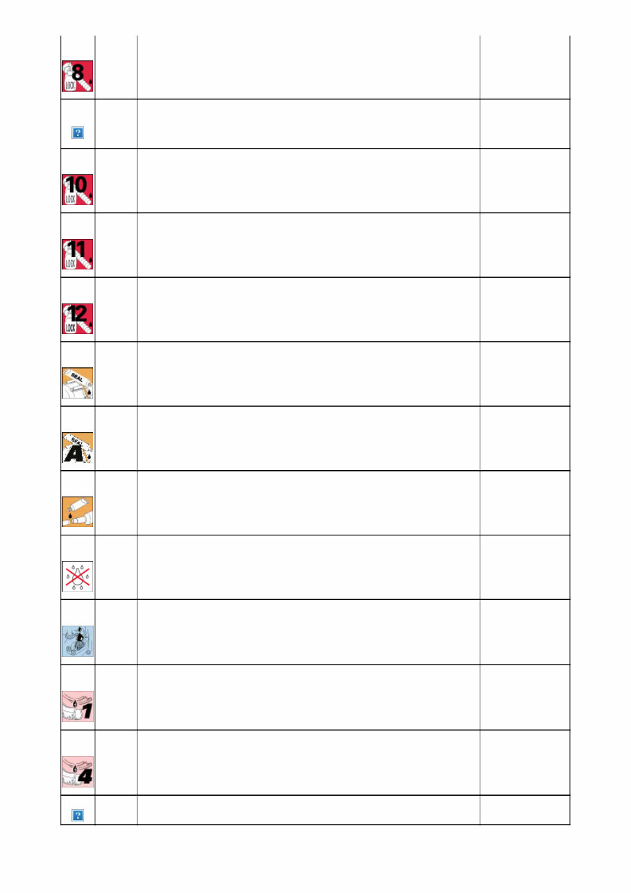
LOCK 8 High-strength retaining compound for threaded parts, bearings, bushes, splines and keys. Operating temperature range: 55 to 150 °C. Loctite 601 (As an alternative THREE BOND TB1378B) LOCK 9 Medium-strength threadlocker. Loctite 406 LOCK 10 Product for metal parts to seal and lock freely sliding cylindrical couplings or threaded couplings. Resistant to high mechanical stress and high temperature, excellent resistance to solvents and chemical attack. Loctite 128443 (former 648 AV) LOCK 11 Medium-strength threadlocker. Loctite 401 LOCK 12 Instant adhesive gel offering tensile/shear strength. Loctite 454 gel DUCATI sealing compound. THREE BOND 1215 Sealing compound THREE BOND 1207B Exhaust pipe sealing paste. Self-sealing paste hardens when heated and resists temperatures exceeding 1000 °C. Holts Firegum Spray used to protect electric systems. Eliminates moisture and condensation and provides excellent corrosion resistance. Water repellent. SHELL Advance Contact Cleaner Dry lubricant, polymerising on contact with air. Molykote D321R Molykote M55 Plus Emulsion for lubrication of rubber. P 80 Protection lubricant emulsion. KLUBERPLUS S 06/100 Lubricant for mechanical elements Castor oil
General maintenance indications Useful tips Ducati recommends that you follow the instructions below in order to prevent problems and obtain the best end result: - when diagnosing faults, primary consideration should always be given to what the customer reports about motorcycle operation since this information can highlight anomalies; your questions to the customer concerning symptoms of the fault should be aimed at clarifying the problem; - diagnose the problem systematically and accurately before proceeding further. This manual provides the theoretical background for troubleshooting; this basis must be combined with personal experience and attendance at periodic training courses held by Ducati; - repair work should be planned carefully in advance to prevent any unnecessary downtime, for example obtaining the required spare parts or preparing the necessary tools, etc.; - limit the number of operations needed to access the part to be repaired. Note that the disassembly procedures in this manual describe the most efficient way to reach the part to be repaired. General advice on repair work - Always use top quality tools. When lifting the motorcycle, only use devices that comply fully with the relevant European directives. - When working on the motorcycle, always keep the tools within reach, ideally in the order required, and never put them on the motorcycle or in hard-to-reach or inaccessible places. - The workplace must be kept clean and tidy at all times. - Always replace gaskets, sealing rings and split pins with new parts. - When loosening or tightening nuts or screws, always start with the largest or start from the centre; tighten nuts and screws to the specified torque working in a crosswise sequence. - Always mark any parts and positions which might easily be confused at the time of reassembly. - Use exclusively Ducati original replacement parts and the recommended brands of lubricants. - Use special service tools where specified. - Ducati Technical Bulletins often contain updated versions of the service procedures described in this manual. Check the latest Bulletins for details.
2014-2015 Ducati 899 Panigale Service & Repair Manual
Thank you for considering the 2014-2015 Ducati 899 Panigale Service & Repair Manual. This manual provides detailed, step-by-step instructions and clear pictures covering every service and repair procedure you will need for your Ducati 899 Panigale.
DESCRIPTION:
Save money and gain confidence by performing your own repairs with this comprehensive manual. It is designed to simplify every task with easy-to-follow procedures and clear, detailed images. Once acquired, this manual is yours to keep forever and can be printed by page, chapter, or in its entirety, and even transferred to your tablet or smartphone for convenience.
MODELS COVERED:
Specifically designed for the 2014-2015 Ducati 899 Panigale, this manual covers all engine, trim, and transmission configurations relevant to this model.
CONTENTS:
This high quality Service & Repair Manual includes every repair procedure from A to Z.
All essential repair and service procedures are comprehensively covered.
COMPUTER REQUIREMENTS:
This downloadable manual works on all PC and MAC computers, tablets, and mobile phones. It requires only Adobe Reader, which is typically pre-installed or can be downloaded for free.
INSTANT DELIVERY:
Upon payment by Visa, MasterCard, or PayPal, the manual will be instantly emailed to the address provided at checkout.
Customer Satisfaction Guaranteed.
Recently Viewed
5,521,897Happy Clients
2,594,462eManuals
1,120,453Trusted Sellers
15Years in Business
Price:
Actual Price:
2014-2015 Ducati 899 Panigale Service & Repair Manual