

Derbi GPR 125 4-stroke Motorcycle Service & Repair Manual
What's Included?
Fast Download Speeds
Online & Offline Access
Access PDF Contents & Bookmarks
Full Search Facility
Print one or all pages of your manual

WORKSHOP MANUAL
GPR 125 4-stroke

INTRODUCTION ...................................................................
SAFETY REGULATIONS ......................................................
MAINTENANCE REGULATIONS .......................................
SPECIAL TOOLS FOR THE ENGINE ..................................
SPECIAL TOOLS - CHASSIS ..............................................
TECHNICAL DATA ...............................................................
TIGHTENING TORQUES .....................................................
PDI (Pre-delivery inspection) .................................................
LOCATION OF ELEMENTS .................................................
REMOVING BODYWORK ELEMENTS ................................
PERIODICAL MAINTENANCE TABLE .................................
LUBRICATION POINTS .......................................................
INSPECTION AND MAINTENANCE ..................................
INSPECTION AND MAINTENANCE .................................
IDENTIFICATION OF SETS ...................................................
REMOVING THE ENGINE FROM THE FRAME ...................
DISMANTLING THE ENGINE ...............................................
INSPECTING THE ENGINE ELEMENTS ...............................
ASSEMBLING THE ENGINE ..................................................
FITTING THE ENGINE INTO THE FRAME ...........................
DISMANTLING THE CARBURETTOR ...................................
ASSEMBLING THE CARBURETTOR ......................................
CHECKING LEVEL OF THE FLOAT CHAMBER ...................
CHECKING THE VACUM VALVE AND TAPERED NEEDLE ...........
CHECKING THE AUTOMATIC CHOKE ..............................
ENGINE
4
9
10
13
16
17
26
31
34
36
48
51
52
83
85
89
91
104
119
150
155
160
164
164
166
FUEL
SYSTEM
CONTENTS
4
5
MAINTENANCE
3
1
GENERAL
INFORMATION
0
2

COOLING
SYSTEM
CHASSIS
BRAKE SYSTEM
CONTENTS
DIAGRAM OF THE SYSTEM ..................................................
DESCRIPTION OF THE SYSTEM AND CHECKING OF ELEM ....
RENEWING THE WATER PUMP OIL SEAL ..........................
DIAGRAM OF THE SYSTEM ..................................................
DESCRIPCIÓN OF THE LUBRICATION SYSTEM ................
INSPECTING THE WHEELS ...................................................
FRONT WHEEL .......................................................................
FRONT SUSPENSION ...........................................................
STEERING ................................................................................
REAR WHEEL ...........................................................................
REAR SUSPENSION ...............................................................
FRONT BRAKE ........................................................................
REAR BRAKE ............................................................................
GENERAL INDICATIONS ......................................................
LOCATING ELECTRICAL COMPONENTS ..........................
WIRING DIAGRAM ................................................................
CHARGING SYSTEM .............................................................
IGNITION SYSTEM ................................................................
STARTER MOTOR SYSTEM ....................................................
INSTRUMENT PANEL .............................................................
LIGHTING AND INDICATING .............................................
FITTING NEW COMPONENTS ............................................
INSPECTING THE BATTERY AND FUSES ............................
6
7
8
9
10
169
171
175
179
181
185
187
189
195
198
200
203
211
221
223
224
225
226
227
228
235
241
245
LUBRICATING
SYSTEM
ELECTRICAL SYSTEM
4
0 - INTRODUCTION
Particularly important items of information in this manual are distinguished by the following annota-
tions:
Indicates a serious possibility of suffering SEVERE PERSONAL INJURIES OR DEATH if the instructions are
not followed.
Indicates the possibility that the ELEMENT WILL BE DAMAGED if the instructions are not followed.
Presents USEFUL INFORMATION.
This manual has been produced by Nacional Motor, S.A.U. for use by DERBI dealer and sub-agency works-
hops. It is assumed that those using this publication for training purposes and for repairing DERBI machines
have a basic knowledge of mechanics and of the methods inherent in the technique of vehicle repair. Signifi-
cant variations in the characteristics of the machines or in the specific repair operations will be communicated
by means of updates to this manual.
Completely satisfactory work cannot however be carried out without the availability of suitable facilities
and tools, which is why we ask you to consult the pages of this manual referring to special tools and imple-
ments.
NACIONAL MOTOR, S.A.U.
CAUTION
The DERBI logo is the registered trademark and property of DERBI - Nacional Motor, S.A.U.
The total or partial reproduction of any photograph, graphical image or text inserted in this manual is prohibited.
© 2009 DERBI - Nacional Motor, S.A.U.
Created by: www.ciandisseny.com
WARNING
N.B.
5
0 - I NTRODUCTION
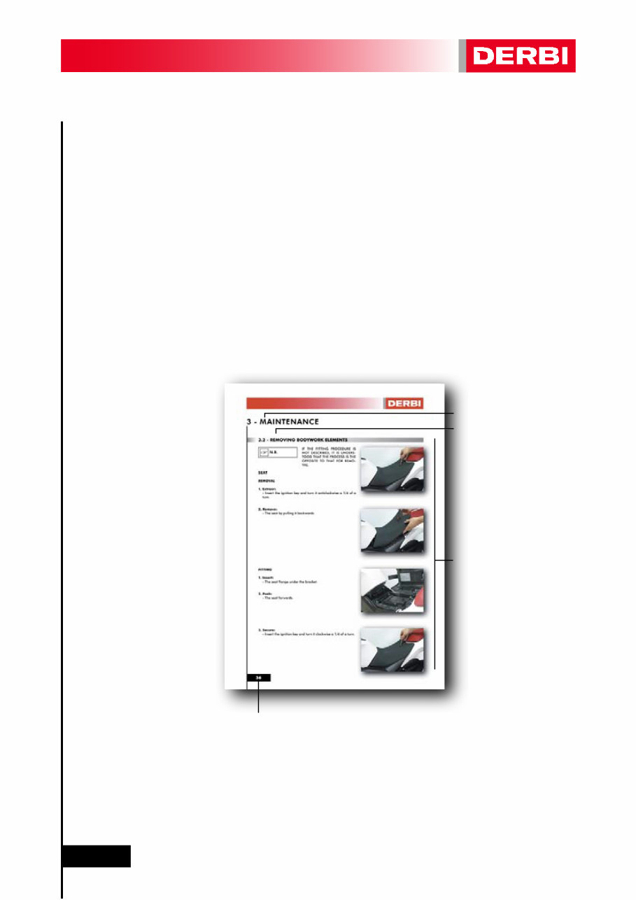
The aim of this manual is to provide the mechanic with a handy and easy to use reference source. It contains
comprehensive explanations of all the installation, extraction, dismantling, assembly, repair and checking
procedures organized step by step in sequence.
Each chapter is divided into sections whose titles appear at the top of each page.
The titles of the subsections appear in a smaller format than the section titles.
Each operation is accompanied by photographs or illustrations.
Numbering corresponding to the chapter.
1
2
3
4
4
3
1
2
6
0 - INTRODUCTION
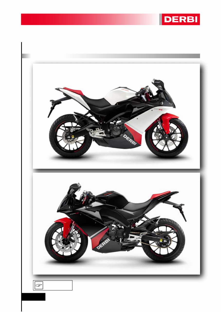
LEFT-HAND SIDE (facing forwards)
RIGHT-HAND SIDE (facing forwards)
VIEWS OF THE MACHINE
Whenever Right-hand or Left-hand Side are specified in this manual, it
is understood as meaning facing forward (i.e. in the riding direction).
N.B.
7
0 - I NTRODUCTION
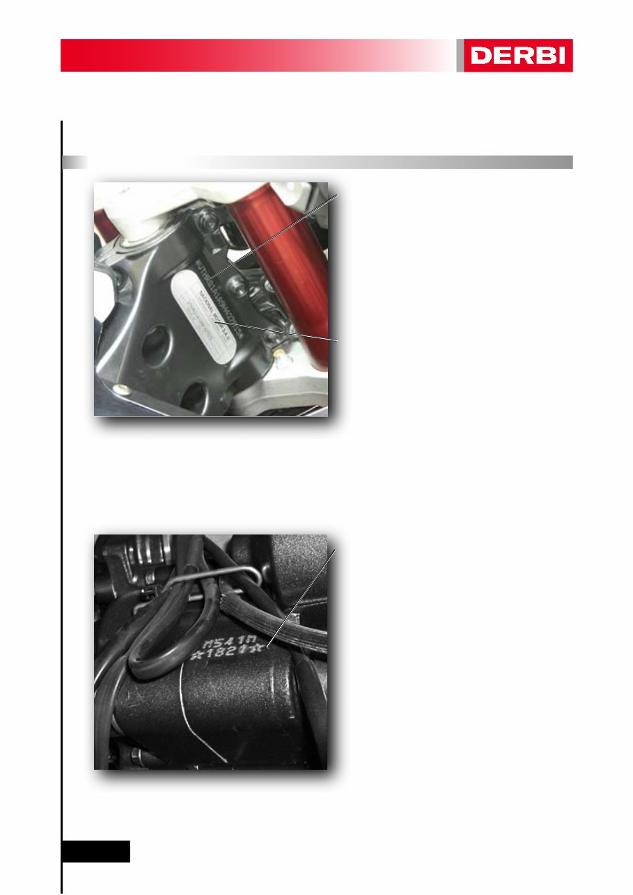
IDENTIFICATION OF THE MACHINE
FRAME SERIAL NUMBER
VTHRG1A1Axxxxxxxx
The frame serial number is located to the right
of the steering column.
MANUFACTURER’S PLATE
The manufacturer’s plate is located to the right
of the steering column.
It includes information about the exhaust
system’s noise emissions (useful in MOT inspec-
tions).
ENGINE SERIAL NUMBER
*
xxxx
*
The frame serial number is on the rear of
the chassis.

8
1 - GENERAL INFORMATION
SAFETY REGULATIONS ............................................................
MAINTENANCE REGULATIONS .............................................
SPECIAL TOOLS FOR THE ENGINE .......................................
SPECIAL TOOLS FOR THE CHASSIS .......................................
TECHNICAL DATA ....................................................................
TORQUE TIGHTENING VALUES .............................................
9
10
13
16
17
26
1.1 -
1.2 -
1.3 -
1.4 -
1.5 -
1.6 -
1 - G ENERAL INF ORMATI ON
9
1.1 - SAFETY REGULATIONS
- In the event of having to carry out work on the machine while the engine is running, ensure that the work
area is well ventilated, where possible using suitable extractor fans. Never leave engines running in closed
spaces. The exhaust gases produced contain CO (carbon monoxide) which can cause loss of consciousness
and can lead to death when inhaled.
- The battery electrolyte contains sulphuric acid. Protect eyes, clothing and skin. Sulphuric acid is highly co-
rrosive; in the event of contact with the eyes or skin, wash with copious amounts of water and seek medical
attention immediately. If electrolyte is swallowed accidentally, drink copious amounts of water or milk and seek
medical attention immediately.
- The battery produces hydrogen, a gas that can be highly explosive. Do not smoke, and avoid flames or sparks
close to the battery, especially during battery charging operations.
- Avoid prolonged contact of used engine oil with the skin. Either wear gloves or wash your hands on finishing
handling used oil.
- Petrol is extremely inflammable, and in certain conditions can be explosive. Do not smoke, and avoid sparks
or other points of ignition in the work area.
- Clean brake pads in a well-ventilated place. DO NOT use compressed air to clean brake pads or brake calli-
pers. Although the dust does not contain asbestos, its inhalation can cause respiratory illnesses.
- Brake liquid attacks painted surfaces very aggressively. Protect painted elements with a clean cloth when
performing operations with brake fluid. Wear gloves if possible, since contact of brake fluid with the skin is not
advisable.
- Prevent coolant from spilling onto hot elements, since it produces an “invisible flame” which may lead to a
person receiving burns as a result of not seeing the flame.
- Do not remove the radiator cap when the engine is hot, since the coolant is under pressure and at a high
temperature, and may cause severe burning.
- If coolant enters the eyes, they must be washed immediately with cold water and medical attention sought.
- During normal functioning, the exhaust system and the engine are at a high temperature.
If work has to be carried out on these, either wait until they have cooled down or wear suitable gloves to avoid
being burnt.
WARNING
1 - G ENERAL INF ORMATI ON
10
1.2 - MAINTENANCE REGULATIONS
- Use genuine DERBI spare parts and lubricants recommended by DERBI. Non-genuine or unauthorised parts
may damage the machine.
- Only use the specific tools intended for this machine.
- During re-assembly, always use new oil seals, gaskets, piston rings and grommets.
- After dismantling, clean the components with solvents that are non-inflammable or that have a high flam-
mability point. Grease all working surfaces before assembling, excluding tapered joints.
- After assembly, check that all components have been correctly fitted and that they are functioning perfectly.
- For dismantling, checking and re-assembly operations use only tools with metric measurements. Metric
screws, nuts and bolts are not interchangeable with imperial measurement joining devices. Using unsuitable
tools and joining devices may damage the machine.
- In the case of work on the machine’s electrical circuitry, check that electrical connections have been correc-
tly fitted, especially the earth connections.
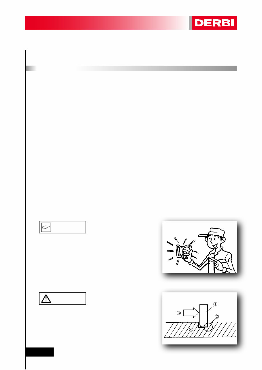
Use only genuine DERBI spare parts. For all lubrication tasks use
oils and greases recommended by DERBI. Other makes make
seem similar in their function and appearance, but are inferior
in quality.
Examine all the locking rings carefully before fitting. Always re-
place the gudgeon pin circlips after every use. Replace distorted
locking rings. On fitting a locking ring (1), ensure that the sharp
edge (2) is on the opposite side to the force (3) to be applied to
it.
See the figure on the side, (4) Axle.
CAUTION
N.B.
You're Reading a Preview
What's Included?
Fast Download Speeds
Online & Offline Access
Access PDF Contents & Bookmarks
Full Search Facility
Print one or all pages of your manual
$28.99
$37.99
Viewed 78 Times Today


Secure transaction
What's Included?
Fast Download Speeds
Online & Offline Access
Access PDF Contents & Bookmarks
Full Search Facility
Print one or all pages of your manual
$28.99
$37.99
Get your hands on the Derbi GPR 125 4-stroke Motorcycle Service & Repair Manual for comprehensive instructions and detailed diagrams covering all workshop procedures. Whether you're a professional mechanic or a DIY enthusiast, this manual is your go-to resource for servicing and repairing your vehicle at home.
Why consider a little DIY action? Well, it's a great excuse to dodge other household chores, a chance to expand your collection of awesome tools, and an opportunity to potentially save money by fixing your car yourself. Ready to roll up your sleeves and get started?
This manual covers the following models:
- Derbi GPR 125 4-stroke
Service workshop Manual Covers:
- GENERAL INFORMATION
- SAFETY REGULATIONS
- MAINTENANCE REGULATIONS
- SPECIAL TOOLS FOR THE ENGINE
- SPECIAL TOOLS FOR THE CHASSIS
- TECHNICAL DATA
- TORQUE TIGHTENING VALUES
- PDI (Pre-delivery inspection)
- MAINTENANCE
- LOCATION OF ELEMENTS
- REMOVING BODYWORK ELEMENTS
- MAINTENANCE TABLE
- LUBRICATION POINTS
- INSPECTION AND MAINTENANCE
- MAINTENANCE PIECES
- ENGINE
- IDENTIFICATION OF SETS
- REMOVING THE ENGINE FROM THE FRAME
- DISMANTLING THE ENGINE
- INSPECTING THE ENGINE ELEMENTS
- ASSEMBLING THE ENGINE
- FITTING THE ENGINE INTO THE FRAME
- FUEL SUPPLY SYSTEM
- DISMANTLING THE CARBURETTOR
- ASSEMBLING THE CARBURETTOR
- CHECKING THE FLOAT CHAMBER LEVEL
- CHECKING THE VACUUM VALVE AND TAPERED NEEDLE ...
- CHECKING THE AUTOMATIC CHOKE
- COOLING SYSTEM
- DIAGRAM OF THE SYSTEM
- DESCRIPTION OF THE SYSTEM AND CHECKING OF ELEMENTS
- RENEWING THE WATER PUMP OIL SEAL
- LUBRICATION SYSTEM
- DIAGRAM OF THE SYSTEM
- DESCRIPCION OF THE LUBRICATION SYSTEM
- CHASSIS
- INSPECTING THE WHEELS
- FRONT WHEEL
- FRONT SUSPENSION.
- STEERING
- REAR WHEEL
- REAR SUSPENSION
- BRAKING SYSTEM
- FRONT BRAKE
- REAR BRAKE
- ELECTRICAL SYSTEM
- GENERAL INDICATIONS
- LOCATING ELECTRICAL COMPONENTS
- WIRING DIAGRAM
- CHARGING SYSTEM
- IGNITION SYSTEM
- STARTER MOTOR SYSTEM
- INSTRUMENT PANEL
- LIGHTING AND INDICATION
- FITTING NEW COMPONENTS
- INSPECTING THE BATTERY AND FUSES
File Format:
- If the title includes "Software": .OVA file manual (non-interactive)
- If the title does not include "Software": .PDF manual
Compatibility:
- All Versions of Windows & Mac
Language:
- English
Requirements:
- Adobe Reader


