

Derbi Manuals for mechanics
What's Included?
Fast Download Speeds
Offline Viewing
Access Contents & Bookmarks
Full Search Facility
Print one or all pages of your manual

This manual has been prepared by DERBI Nacional Motor, S.A. Sociedad
Unipersonal for use by concessionaires and DERBI sub-agency workshops. It is
assumed that persons using this work for the maintenance and repair of
DERBI vehicles will have a basic grounding in the principles of mechanics
and the necessary technical methods used in the repair of such vehicles.
Major variations in the technical specifications of the vehicles or in specific
repair operations will be communicated by means of updates to this manual.
Nevertheless, completely satisfactory work cannot be performed without the
necessary installations and tools: for this reason we strongly recommend that
you consult the pages in this manual which refer to specific tools and equip-
ment.
Information in this manual which is of particular importance is indicated by
the following notes:
N.B. This indicates a note which gives key information for performing the
procedure more easily and clearly.
This indicates specific procedures which should be followed to
avoid causing damage to the vehicle.
This indicates procedures which should be followed to avoid
possible injury to the person carrying out the repairs to the vehicle.
Caution!
Warning !!!
All data may be changed without prior notice.
Derbi declines all responsibility for the use of non-original parts and accessories
which have not been tested and approved.
1
DERBI - NACIONAL MOTOR Sociedad Unipersonal / 2002 • Dep. Leg. GI-1302-2000 • N.º 80881158407
fourth edition - May 2002

2

3
INDEX
Predator-LC / O2 Atlantis-LC / O2 / 100 Models
Hunter - Paddock - Vamos Models
Technical specifications of the engine _4
Special tools_____________________5
Regular maintenance table _________6
Torque settings___________________7
Front forks - HUNTER _____________8
Front forks - PADDOCK ____________9
Front forks - VAMOS ______________9
Withdrawing the engine
from the frame ________________10
Stripping the engine ______________11
Assembly of the engine ___________16
Crankshaft inspection_____________18
Assembly of right hand crankcase
bearing ______________________19
Water pump ____________________20
Assembly of sliding weight hub _____22
Clutch assembly_________________23
Reduction gear__________________24
Left hand crankcase cover _________24
Cylinder head, cylinder,
and piston ____________________27
Carburettor _____________________30
Cylinder sleeve cover,
radiator and filter box ___________33
Fitting the engine in the frame ______35
Electrical system ________________36
Electrical wiring diagrams _________45
Regular Maintenance Table ________50
Torque settings__________________51
Front forks _____________________52
Rear suspension ________________54
Removing the engine
from the frame ________________56
Magneto _______________________57
Cylinder head, cylinder and piston ___58
Crankshaft - Variable speed unit ____60
Carburettor _____________________61
Electrical system ________________62
Electrical wiring diagrams _________65
Engine Piaggio Models
Special tools_________________________74
Regular Maintenance Table __________77
Torque settings ______________________78
Paioli front forks _____________________79
Engine ______________________________80
Magneto_____________________________81
Electronic ignition ____________________83
Transmission - mixer_________________84
Cylinder head - cylinder - piston
(Liquid cooled models) ____________95
Crankcase halves - crankshaft _______98
Secondary air system_______________102
Cylinder head - cylinder - piston
(Air cooled models) ______________104
Vehicle service data ________________107
Carburettors ________________________110
Electrical system____________________111
Electrical wiring diagrams ___________113
1
2
3

4
Engine
Number of cylinders .................1
Cycle ........................................2-stroke
Stroke and Bore .......................41 x 37.4 mm
Cubic capacity..........................49cc
Fuel admission .........................reed valve direct to crankcase
Compression ratio ....................11.5 : 1
Starter system ..........................electric start
Engine cooling system .............fan-driven pressurised air
LC: liquid cooling
Fuel ..........................................Unleaded fuel
Lubrication system ...................petrol-oil mixture, using constant flow pump driven lubrication
Atlantis 100:
Stroke and Bore .......................50 x 43 mm
Cubic capacity..........................85cc
Compression ratio ....................9.5 : 1
Carburettor
Type .........................................DELL’ORTO PHVA 10.GD / PHVA12 DD / PHVA 14 DD / PHVA 17.5
WEBER 14 OM 1 AA / WEBER 14 OM 1 BA / WEBER 12 OM 1 QA
WEBER 12 OM 1 SA / WEBER 14 OM 1 FA
Primary drive...............................automatic variable speed unit through trapezoidal belt drive
Clutch ..........................................automatic centrifugal dry clutch
Ignition
System .....................................magneto 12V 80W.
Ignition advance .......................18º before T.D.C.
Spark plug ................................NGK B8 HS / CHAMPION L.78 C.
NGK B9 ES / CHAMPION N.2.C / NGK B8 ES / CHAMPION N3C
Battery......................................12V 4Ah
TECHNICAL SPECIFICATIONS OF THE ENGINE
5
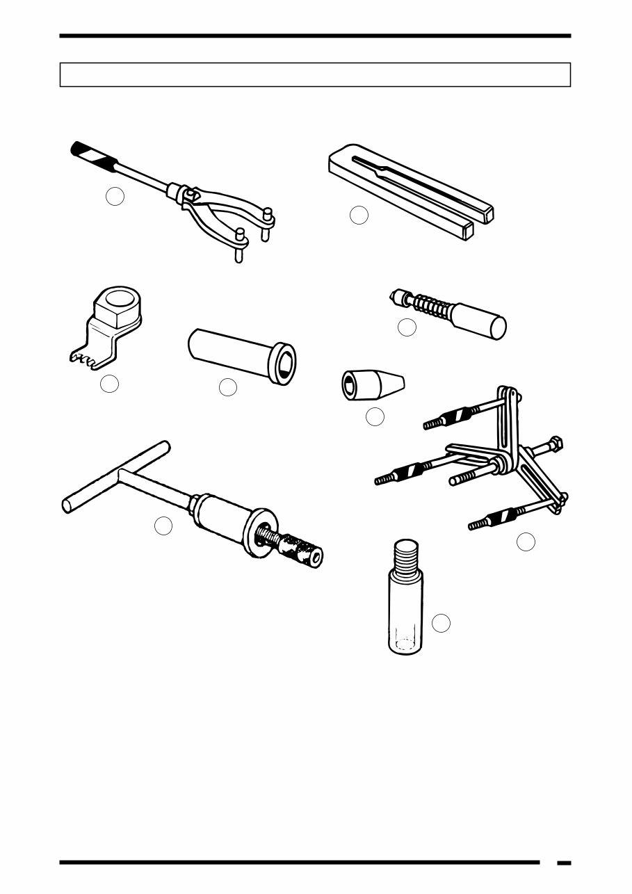
Part Name Reference Number
1.- Magneto disassembly tool unit ..............................................................0.0G.053.0.001.1
2.- Connecting rod blocking tool .................................................................0.0G.056.0.037.1
3.- Water pump shaft extractor tool ............................................................0.0G.056.0.042.1
4.- Crankshaft assembly tool (use for water pump shaft) ...........................0.0G.056.0.036.1
5.- Crankshaft seal guide bush ...................................................................0.0F .053.0.084.1
6.- Crankshaft seal assembly punch ..........................................................0.0F .054.0.045.1
7.- Gudgeon pin circlip assembly tool ........................................................0.0G.056.0.041.1
8.- Water pump pinion blocking tool ...........................................................0.0G.053.0.098.1
9.- Engine splitting tool ...............................................................................0.0G.053.0.015.1
SPECIAL TOOLS
1
8
6
4
5
3
9
7
2

6
REGULAR MAINTENANCE TABLE
Período: este período puede Km 1000 2500 5000 10000 15000 20000 25000
valorarse según los kilómetros
Months 2 6 12 24 36 recorridos o el tiempo en meses
Reduction gear or crankcase oil Replace Check Check Replace Check Replace Check
Suspensions Check Check Check Check Check
Tighten all fastenings Check Check Check Check Check Check Check
Electrical connections Check Check Check Check Check Check Check
Spark plug Clean Adjust Replace Replace Replace Replace Replace
Carburettor Adjust Adjust Adjust Adjust Adjust Adjust
Clean Clean Clean Clean Clean Clean
Water pump drive belt Replace
Variable speed drive rollers Check
drive belt transmission Replace
Oil filter Check Replace Check Replace Check
Air filter Clean Clean Clean Clean Clean
Brakes / hose / pads Check Check Check Check Check
Brake equipment Check Check
Brake fluid EVERY 2 YEARS EVERY 2 YEARS
Tyres Check Check Check Check Check
Tyres pressures Check Check Check Check Check Check Check
Fuel or oil hoses Check Replace Check Replace Check
Transmission Lubricate Lubricate Lubricate Lubricate Lubricate
Cylinder head nuts Tighten up Tighten up
Inlet valve reeds Check Check
Period: the period may be calcu-
lated by kilometres run or by
time in months

7
PART NAME TORQUE SETTING
(Nw x m.)
BRAKE SHOE ROTATION SHAFT 8M125 17 - 19 LOCTITE
CYLINDER STUD 6M100 STUD 10 - 12
CRANKCASE HALVES 6M100 SCREW 9 - 10 LOCTITE
CYLINDER HEAD 6M100 NUT 10 - 12
INLET MANIFOLD VALVE BRACKET 4M70 SCREW 1 - 2 LOCTITE
CRANKCASE INLET MANIFOLD 6M100 SCREW 9 - 10 LOCTITE
OIL PUMP 5M80 SCREW 4 - 5 LOCTITE
COIL TO BASE PLATE 6M100 SCREW 8 - 10 LOCTITE
BASE PLATE TO CRANKCASE 6M100 SCREW 8 - 10 LOCTITE
MAGNETO 10M100 NUT 35 - 40 LOCTITE
STARTER MOTOR 6M100 SCREW 9 - 10 LOCTITE
FAN TO MAGNETO 6M100 SCREW 8 - 10 LOCTITE
ENGINE BRACKET PLATE A.E. 6M100 SCREW 9 - 10 LOCTITE
LEFT HAND SIDE CRANKSHAFT 10M100 NUT 35 - 40 LOCTITE
REDUCTION GEAR COVER 6M100 SCREW 9 - 10 LOCTITE
PULLEY SHAFT 10M100 NUT 35 - 40 LOCTITE
PLASTIC OIL FILLER CAP 14M150 CAP HAND TIGHT
LEFT HAND CRANKCASE COVER 6M100 SCREW 9 - 10 LOCTITE
OIL DRAIN PLUG 8M125 SCREW 17 - 19
CYLINDER SLEEVE 6M100 SCREW 9 - 10
FRONT WHEEL 12M150 NUT 50 - 60
REAR WHEEL 16M150 NUT 100 - 105
SWINGING ARM 10M150 NUT 40 - 45
SHOCK ABSORBER UPPER/LOWER 10M150 NUT 40 - 45
HANDLEBAR 8M125 SCREW 20 - 25
EXHAUST PIPE TO CYLINDER 6M100 SCREW 8 - 12
EXHAUST PIPE - INTERMEDIATE 6M100 NUT 8 - 12
EXHAUST PIPE TO CRANKCASE 10M150 SCREW 40 - 45
FORK LEG CLOSURE 6M100 NUT 8 - 12
STEERING 25M100 NUT 70 - 90
FRONT BRAKE 8M125 SCREW 20 - 25
KICK START PEDAL 6M100 SCREW 08 - 12 LOCTITE
SILENCER PROTECTOR 4M70 SCREW 1 - 2 LOCTITE
TORQUE SETTINGS
8
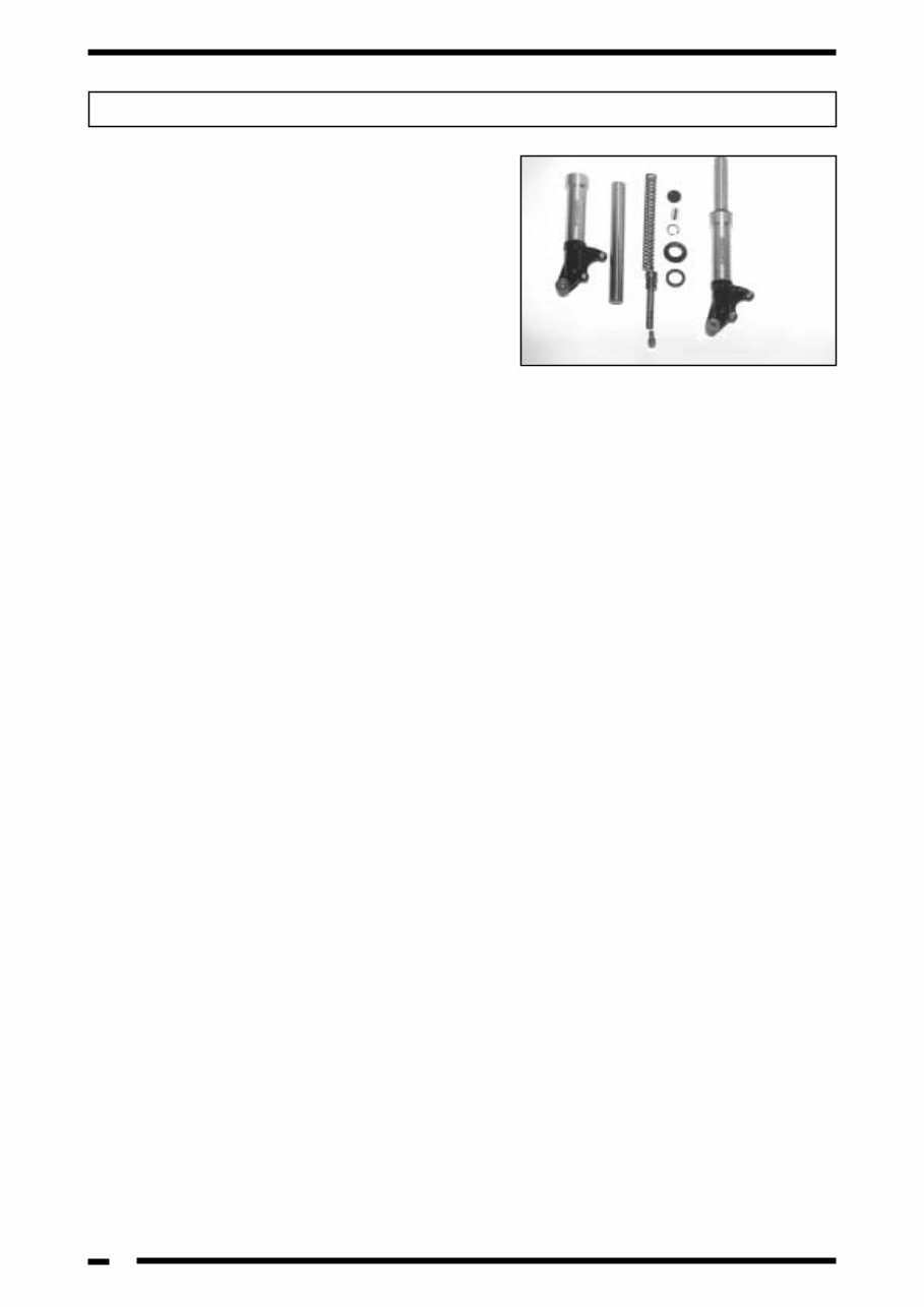
HUNTER MODELS
Stripping the fork legs
- Withdraw the two screws from the brake caliper.
- Withdraw the front wheel axle nut and slacken
the lock screw.
- Withdraw the front wheel axle, the wheel DIS-
TANCE PIECE, and leave the transfer box and
the separator hanging free.
- Withdraw the fork protection plate screw so as to
be able to extract the external fork leg cap.
- Loosen the 10 x 25 screw from the fork plate and
while pushing upwards on the fork leg, release
the fork bar securing clip.
- Withdraw the fork leg from the vehicle.
Both fork legs are the same.
Stripping the left or right hand fork bar
- Withdraw the safety circlip.
- Undo the fork leg tube cap and seal.
- Drain the hydraulic fluid from the bar.
- Extract the fork leg spring.
- Loosen and extract the fork leg screw.
- Withdraw the hydraulic tube and the bar from the
fork leg.
- Extract the dustguard, the seal securing circlip,
and finally the seal.
Note: Clean thoroughly all the parts which are
to be re-fitted; it is mandatory under all cir-
cumstances to replace the O-rings and seals.
Re-assembly of the fork leg
- Fit the seal into the fork leg size 30-40-7/9. Using
special tool 0.0H.054.0.045.1 and insert the seal
securing circlip.
- Insert the hydraulic tube inside the fork bar.
- Insert the bar inside the fork leg, fit the fork spring
and tighten the 10 x 25 screw using a copper
washer and Loctite to a torque of 35 - 40 Nw x m.
- Re-fill using 80 cc of AGIP FORK SAE10W
hydraulic oil.
FRONT FORKS
- Insert the fork leg tube cap with the O-
ring seal, the safety circlip and the dust-
guard.
- Assemble the fork leg into the vehicle.
- Insert the complete fork leg assembly
into the fork plate.
- Fit the safety circlip and the exterior fork
leg cap.
- Tighten the fork plate securing screw.
- Tighten the mudguard/fork plate protec-
tor securing screw.
- Locate the wheel axle, the transfer box,
the transfer box bushing, the wheel, and
fit the brake caliper onto the brake disc;
then the distance piece, the washer, the
spring washer and nut, tightening to a
torque of 50 - 60 Nw x m.
- Tighten the fork leg closure screw to a
torque of 8 - 12 Nw x m.
- Locate the two brake caliper securing
screws (8 x 60) to a torque of 20 - 25
Nw x m. using Loctite. Finally turn the
wheel and operate the brake lever.
9
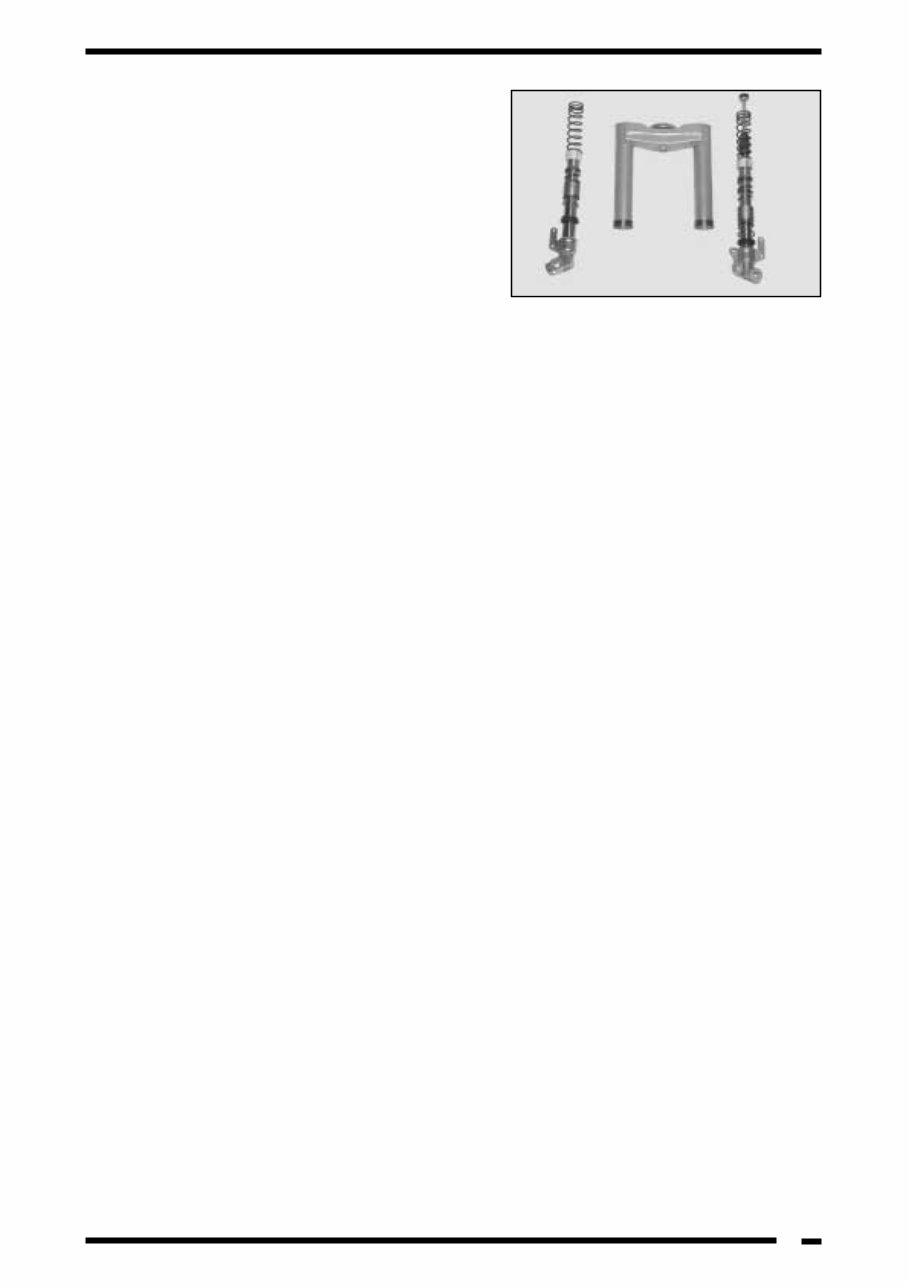
PADDOCK MODELS
Stripping the fork legs
- Withdraw the four mudguard screws and remove
the mudguard.
- Slacken off the wheel axle nut, withdraw the was-
her, loosen the 2 front brake caliper screws, loo-
sen the locking screw, extract the wheel axle, the
axle distance piece and leave the transfer box
and the separator hanging free.
Stripping the left hand fork bar
- To disassemble the left hand fork bar without
stripping the fork the following procedure should
be followed:
- Remove the dustguard and extract the safety cir-
clip.
- Withdraw the two screws securing the bag carrier
hook.
- Withdraw the seven screws securing the inner
shield and remove the inner shield.
- Drill a hole using a 15 mm drill through the fork
plate protector so as to be able to insert a tube
spanner and loosen the 6 x 100 nut and washer;
this way it is possible to withdraw the left hand
fork leg, with the hydraulic cartridge with bushing
and silentbloc, the boss, the rubber stop spring
and the guide washer.
If the hydraulic cartridge loses oil it must be
replaced, since it cannot be repaired.
Right hand fork bar
- Remove the dustguard and the safety circlip.
- Withdraw the right hand fork leg, the lower spring
washer, the rubber stop and the spring.
This fork leg should be filled with AGIP GR MU
3 type grease only.
Re-fitting the two fork legs is carried out in the
reverse order from stripping.
VAMOS MODELS
Stripping the fork legs
- Withdraw the 2 front brake caliper
screws (“separate the caliper”).
- Remove the wheel axle nut, the spring
washer and the washer.
- Withdraw the wheel axle, the transfer
box bushing and the whole transfer box
assembly.
- Loosen the end piece screws, and with-
draw the end pieces.
- Extract the fork leg dustguard and the
safety circlip.
- Withdraw the fork leg, the stop and the
spring.
When re-assembling, carry out the same
procedures in reverse order.
The fork legs should be filled with AGIP
GR MU 3 type grease.
10
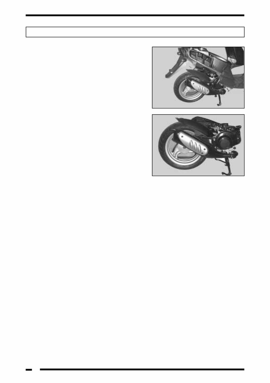
STRIPPING
- Remove the luggage carrier ( 4 screws).
- In PADDOCK models separate the electrical con-
nectors on the turn indicators.
- The left hand footrest cover (1 screw).
- The left hand side panel (2 screws).
- The right hand footrest cover (1 screw).
- The right hand side panel (2 screws).
- Raise the saddle.
- Remove the side panels (5 screws).
- Remove the oil reservoir cap.
- Remove the fuel tank filler cap.
- Remove the anti-freeze reservoir cap on PAD-
DOCK-LC models.
- Remove the helmet carrier box (6 screws).
- Remove the rear brake cable nut.
- Remove the rear brake guide stop (1 screw).
- Remove the engine earth screw.
- Remove the throttle cable union.
- Disconnect the electrical connectors for the mag-
neto, the stop light, the choke, the starter, the
high tension coil and the coil earth cable.
- On the LC models, also disconnect the thermo-
contact spade connector.
- Disconnect the two pipes from the connector on
the carburettor: the fuel pipe and the vacuum line.
- Disconnect the oil hose at the reservoir outlet.
- In PADDOCK-LC models extract the antifreeze
drain plug.
- Remove the cooling hoses where they connect to
the antifreeze reservoir.
- Remove the 2 fixing screws which secure the
engine to the frame.
- Remove the 1 shock absorber screw.
- Separate the engine from the frame.
WITHDRAWING THE ENGINE FROM THE FRAME
You're Reading a Preview
What's Included?
Fast Download Speeds
Offline Viewing
Access Contents & Bookmarks
Full Search Facility
Print one or all pages of your manual
$31.99
Viewed 55 Times Today


Secure transaction
What's Included?
Fast Download Speeds
Offline Viewing
Access Contents & Bookmarks
Full Search Facility
Print one or all pages of your manual
$31.99
These Derbi workshop manuals are a valuable resource for both professional mechanics and DIY enthusiasts. The self-running DVD contains 26 service books, including illustrated parts manuals, making it convenient to access the necessary information. The DVD includes folders for Derbi images and parts manuals, with detailed parts lists for various models such as Atlantis Aire, GPR, Senda, and more. Additionally, it provides workshop manuals for 50cc, 6-speed, service, and specific models like Predator LC and RS50 Motorparts. This comprehensive collection covers a wide range of Derbi models, ensuring that all your repair and maintenance needs are met.
- 26 service books included
- Illustrated parts manuals
- Convenient self-running DVD format
- Valuable resource for professional mechanics and DIY enthusiasts
- Includes detailed parts lists for various models
- Comprehensive workshop manuals for different models


