

DAELIM ROADSPORT ROADWIN R Service Repair Manual 2007-2012
What's Included?
Fast Download Speeds
Online & Offline Access
Access PDF Contents & Bookmarks
Full Search Facility
Print one or all pages of your manual
HEAD OFFICE(FACTORY)
#58, SUNG SAN-DONG, CHANG WON, KYUNGNAM, KOREA
TEL: (82-55) 239-7000 / FAX: (82-55) 239-7520
OVERSEAS SALES OFFICE(FACTORY)
13-5,SEONGSU 1-GA,2DONG, SEONGDONG-GU, SEOUL, KOREA
TEL: (82-2) 3408-2634 / FAX: (82-2) 467-9997
SERVICE MANUAL
2007. 01 PRINTED
2007. 01 PUBLICATION
COPY PROHIBIT
HOW TO USE THIS MANUAL
This manual describes effective maintenance procedure for
the VJF125 manufactured by DAELIM Motor Co., Ltd.
To ensure safety and optimal operating conditions of the
vehicle, carry out regular inspections according to the
maintenance schedule (Section 2).
Sections 1 through 2 provide information on overall
vehicle; and section 3 describes maintenance procedure
for the engine, frame and electrical systems.
To facilitate use of this manual, each page starts with
disassembly and system diagrams, service information,
and troubleshooting guide. If you cannot find the cause of
trouble, refer to Section 21: Troubleshooting.
Contents of this manual and specifications are subject
to change without prior notice for improvement of
vehicle quality.
No part of this publication may be reproduced without
written permission of DAELIM MOTOR.
CONTENTS
GENERAL INFORMATION
INSPECTIONS / ADJUSTMENTS
LUBRICATION
FUEL SYSTEM
ENGINE
COOLING SYSTEM
EMS (
Engine Management System
)
ENGINE REMOVAL
CLUTCH / GEARSHIFT
A.C.GENERATOR / STARTER CLUTCH
CYLINDER HEAD / VALVES
CYLINDER / PISTON
CRANKCASE / TRANSMISSION /
CRANKSHAFT
EXTERNAL PARTS
REAR WHEEL /REAR SUSPENSION
FRONT WHEEL/FRONT FORK/STEERING
HYDRAULIC BRAKE
FRAME ELECTRICAL SYSTEM
BATTERY / CHARGING SYSTEM
ELECTRIC STARTER
LIGHTS/METER/SWITCHES
IGNITION SYSTEM
WIRING DIAGRAM
TROUBLESHOOTING

1-1
1. GENERAL INFORMATION
SERVICE INFORMATION 1-1
SERVICE RULES 1-1
CAUTION WHEN WIRING 1-5
MODEL IDENTIFICATION 1-9
SPECIFICATIONS 1-10
TORQUE VALUES 1-12
SYMBOLS / ABBREVIATIONS 1-14
TOOLS 1-15
WIRING DIAGRAM 1-16
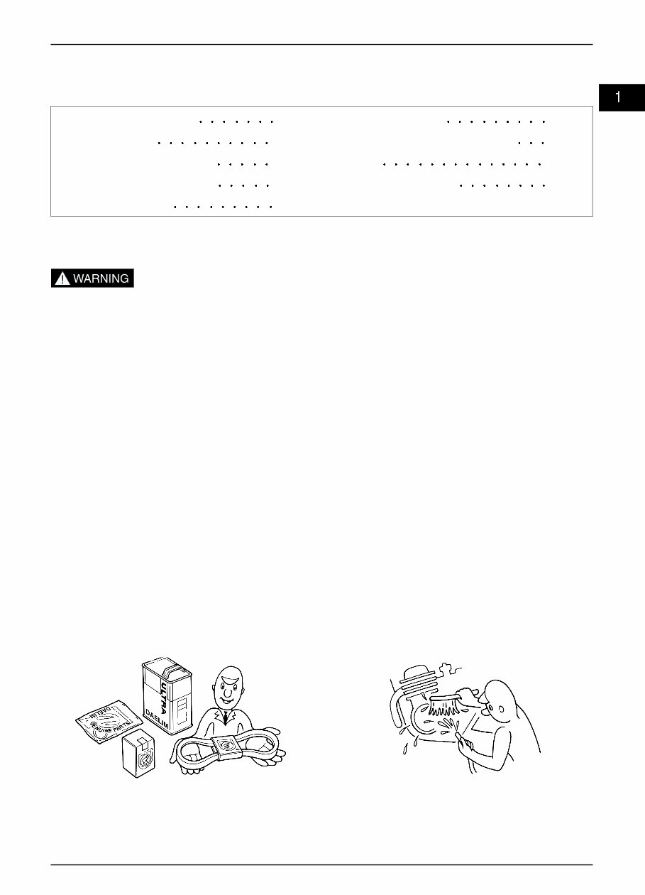
SERVICE INFORMATION
1. Do not run the engine for a long time in closed or not well-ventilated area because the exhaust gas contains toxic
substances such as carbon monoxide, hydrocarbon, nitric oxide.
2. The battery fluid(lean sulfuric acid) is extremely toxic. It is dangerous if skin is exposed to it or if it enters into the eye.
Be careful in handling. When exposed to the battery fluid, wash it with water and get a medical check up.(store the
battery fluid in a safe place to avoid touching by the children)
3. Pay attention not to be burned and always put on the protection gears because the engine or the muffler is hot right after
engine stops.
4. Gasoline is extremely flammable. Maintenance must be performed in the place free of the open fire or electric spark.
5. When more than two person are working, always pay attention to other worker’s action and always have safety in mind.
6. The skin exposed to used engine oil can be a major reason of the skin cancer. Pay attention not to be exposed and wash
carefully with soap and water after handling.
7. If compressed air is used to clean the brake, dust scattered in the air can be breathed in by workers. Please take action not
to scatter dust in the brake cleaner, etc.
8. Flammable nitrogen gas is generated during charging the battery so charging must be performed in well-ventilated area
and free of the open fire and spark.
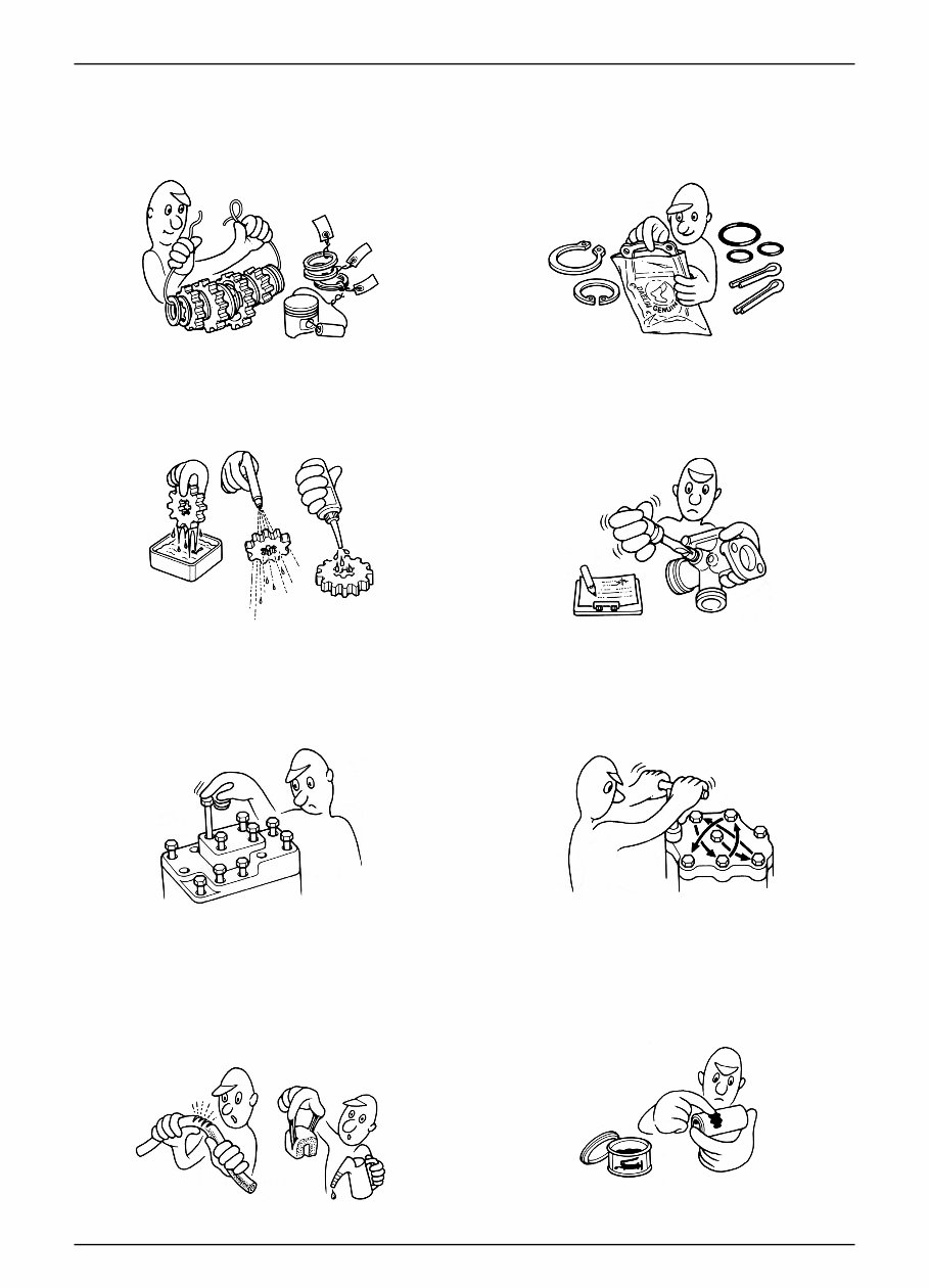
SERVICE RULES
1. Parts and lubrication oil must be DAELIM genuine or
recommended parts.
2. Before maintenance, remove deposit or dust from the
chasis.
1-2
GENERAL INFORMATION
9. Check to see if the rubber part is worn out when
removing it and replace it if necessary. Some rubber part
is weak to gasoline and kerosene, so pay attention not to
soak with gasoline or oils.
10. Recommended grease must be applied to or filled in
the specified place.
7. Align the bolts to uniform the tightening points before
tightening them when you don’t know the bolt length.
8. Bolts, nuts and pieces must be tightened from the bigger
diameter to the smaller one, from inside to outside and
diagonally with the specified torque.
5. Clean the parts after the overhaul and before the test and
remove the cleaning oil with compressed air. Apply oil
to seal face during installation.
6. Check necessary place and measure necessary data
during installation. When installing, return to the state
before removing.
3. Store the parts of each system discriminatively to install
each part in the right place.
4. After removing gasket, O-ring, piston pin clip and cotter
pin, always replace them with the new one. When
removing the snap ring, it can be easily missed after
transformation or installation.
1-3
GENERAL INFORMATION
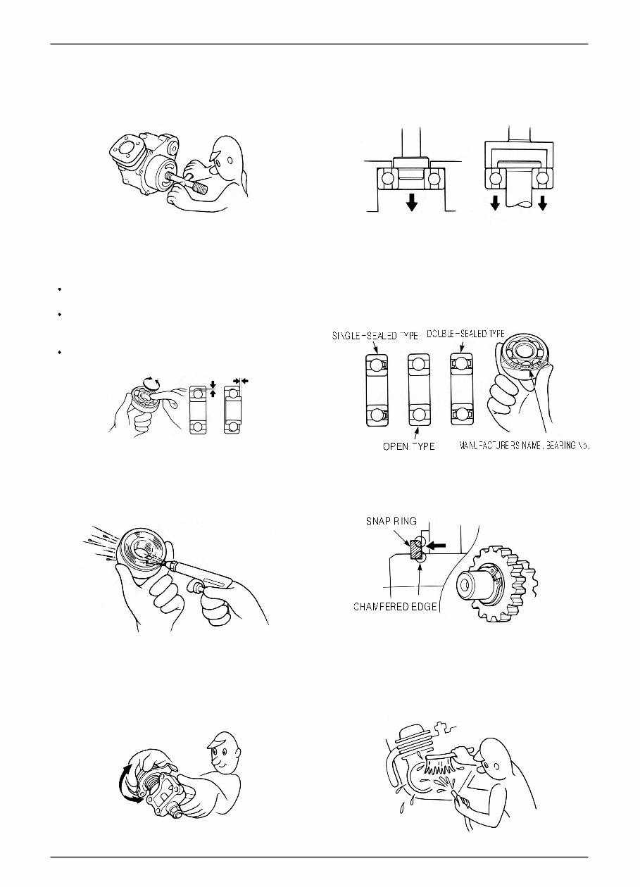
11. Maintenance needed to use the specialized tools must
be performed with the right tool.
12. Never reuse the ball bearing removed with the ball
applied pressure when removing press-fitted the
bearing.
13. Check the smooth rotation of inner or outer race of the
ball bearing by rotating it manually.
Replace the ball bearing having excessive axial/
longitudinal hanging.
Wipe the ball bearing likely to have hanging with
cleaning oil.(except double-sided sealed type ball
bearing)
Replace the ball bearing of which press-fitted part is
slacked at the case or shaft.
14. Pay attention to installation direction in case of the
single-sided sealed ball bearing. Install the open-
direction or double-sided sealed bearing in the way
that the face marked with manufacturer and size
should direct to the outer axle.
15. When blowing the ball bearing with compressed air
after cleaning, keep the race from rotating. High speed
rotation of the race may damage the bearing. Prior to
installation, apply oil or grease to the bearing.
16. Install the snap ring so that chamfered side directs to
the load-applied side. After installation, check the
proper installation by rotating the snap ring.
17. Check each part for proper tightening and operation
after installation.
18. The brake fluid and coolant can damage the painted
plastic or rubber parts. Keep these parts from
contacting with them and wash these parts with water
in case of contact.
’
1-4
GENERAL INFORMATION
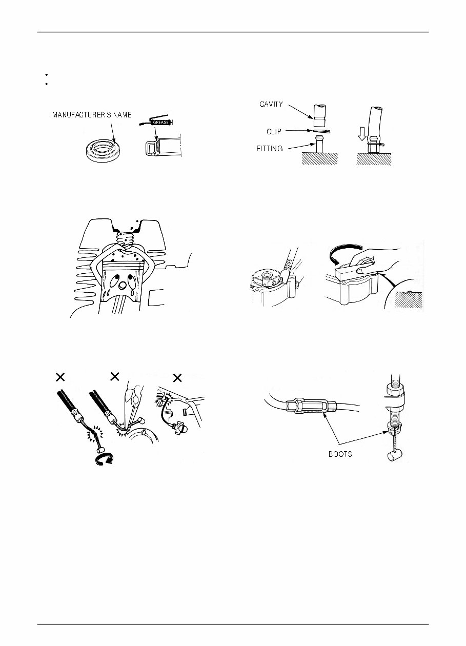
21. Keep the pneumatic system interior or the engine
interior from the infiltration of dust.
22. Install the gasket mounted in the contact surface of
each case of the engine while removing gasket
material completely. Remove damaged contact surface
by wiping with the oil stone equally.
19. Install the oil seal so that the manufacturer marked
surface directs outer surface.(direction not covered
with oil)
Pay attention not to bend or damage the lip.
Apply the grease to the lip.
20. Connect the tube until the tube fully inserted in the
joint. Install the clip if it is supplied. Replace the tube
having slacked end.
23. Pay attention not to bend the cable excessively.
Transformed or damaged cable may cause malfunction
or damage.
24. Install the boots with the installing groove by inserting
the boots into the groove.
’
1-5
GENERAL INFORMATION
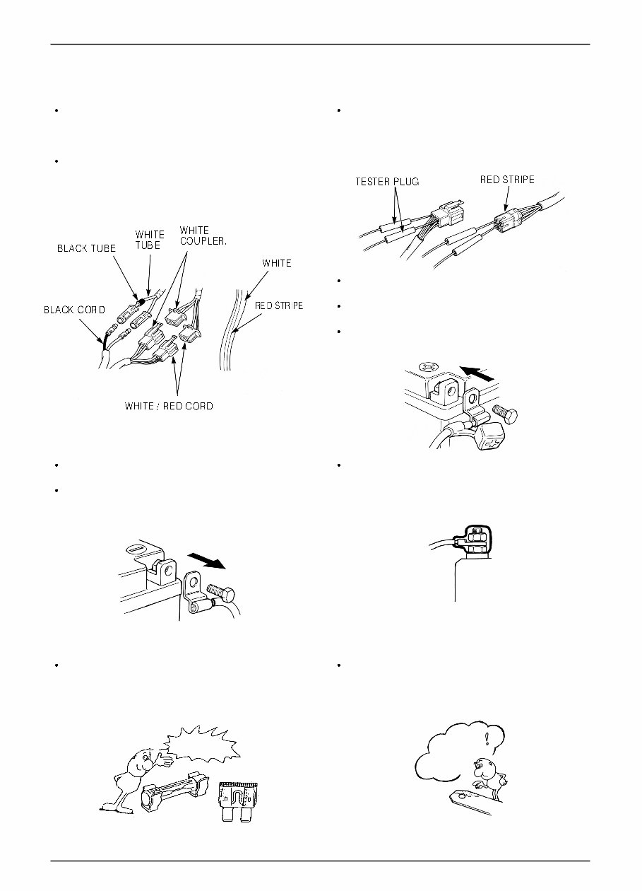
Each cord must be connected depending on its color.
When connecting different cord, attach color tube
around the connector. Connect the coupler to the
connector with same color and same pin number.
Identify the two-colored cord by main color first and
then spriped color .
When measuring voltage or resistance of the cord
terminal using tester, contact the tester plug behind of
the coupler. Pay attention not to open the cord terminal
and contact the tester plug from the front of the coupler
in case of water-proof coupler.
Recheck the condition of contact, securing and
continuity of each part after maintenance.
When connecting the battery, the plus terminal must be
connected first.
After connecting the terminal, apply the grease to the
terminal.
When disconnecting the battery, the minus terminal
must be disconnected first.
Make sure that the tool such as spanner do not contact
with the frame.
Connect covers to the terminal after maintenance.
If the fuse is short-circuited, find out the cause and
repair. Replace with the fuse having the specified
capacity.
If there is rust in the terminal, remove the rust with sand
paper prior to connecting.
CAUTION WHEN WIRING
VALIDATION
OF CAPACITY!
REMOVE
THE
RUST!
1-6
GENERAL INFORMATION
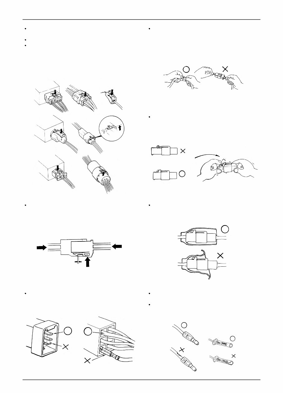
Insert the lock of the coupler until the lock is fully
secured.
Turn off the main switch before connecting/dis-
connecting.
Release the lock to disconnect the lock of the coupler.
The lock of the coupler has two types according to
releasing method(press type and pull type) so release it
properly according to the shape.
- Typical releasing method of the coupler is illustrated in
the following.
When disconnecting the coupler, disconnect it while
holding the coupler body. Pull while holding the wire
harness cord and do not remove the coupler connection.
Release the lock by inserting the coupler slightly and
then narrowing connection to remove the coupler.
Pay attention not to damage the vinyl cover of the
coupler.
Check to see if there is bended terminal and secure it to
avoid disconnecting.
If the wire harness coating is damaged, repair by
winding vinyl tape or replace it.
Prior to connecting the connector, make sure that the
cover is not damaged and the mess terminal is not
opened.
You're Reading a Preview
What's Included?
Fast Download Speeds
Online & Offline Access
Access PDF Contents & Bookmarks
Full Search Facility
Print one or all pages of your manual
$31.99
Viewed 92 Times Today


Secure transaction
What's Included?
Fast Download Speeds
Online & Offline Access
Access PDF Contents & Bookmarks
Full Search Facility
Print one or all pages of your manual
$31.99
Our service repair workshop manual is a comprehensive guide designed for easy readability and covers all repairs from A-Z for all models. It is a valuable resource for both professional mechanics and DIY enthusiasts.
- Maintenance & Servicing
- Engine & Clutch
- Transmissions
- Cooling Systems
- Fuel & Exhaust
- Ignition & Electrical
- Brakes & Brake Assembly
- Wheels & Tires
- Steering & Suspension
- Frame & Bodywork
- Wiring Diagrams
- Fault Finding Troubleshooting
It contains detailed information on all major repair topics along with high-quality pictures and diagrams. The manual is compatible with all operating systems including PC and MAC, ensuring accessibility for all users.


