


BURMAN & SONS,
,_LTD
Ryland Road,
BIRMINGHAM.
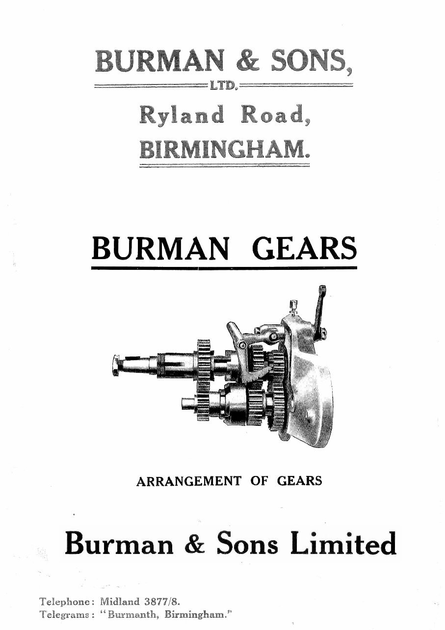
BURMAN GEARS
ARRANGEMENT OF GEARS
Burman & Sons Limited
Telephone : Midland 3877/8.
Telegrams : "Burmanth, Birmingham."
BURMAN & SONS LTD.
RYLAND ROAD,
BIRMINGHAM.
Instructions Leaflet
for
GEAR BOXES
Mcdels "W" "T" "R" "G" "A" "BA" "C" &
I
N s.. -;tting out this leaflet, we will endeavour to explain the general
features of the Burman Gear Box to the advantage of all users.
A feature of the 3-speed Gear Boxes "T," "W," "R" & "G." is that
the lay-out is identical in each box. The same practice is also followed
in the 4-speed units "BA," "C" and "A," there being only a slight varia-
tio-i in the Model "A" in the clutch operation and selector mechanism.
In view of the above remarks, the following instructions can be
applied according to the type of Gear Box (3 or 4-speed) which is being
overhauled.
One of the main features is that all gears, in both 3 and 4-speed
units, are constantly in mesh, and gear changes are effected by means
of dog clutches of ample dimensions (with the exception of certain 1934
Gear Boxes which will be described in a later paragraph). The positions
of the gears themselves are controlled inside the Gear Box, independ-
ently of tank quadrants, by means of a patent rack and pawl mechanism,
this providing an efficient gear change without fear of overshooting the
required position.
Models "R" "T" "W" and "G" Gear Boxes.
To dismantle a Gear Box of the 3-speed type, it is necessary first to
remove the clutch lever bracket and kickstarter, after which the nut on
the kickstarter end of the mainshaft should be unscrewed. To unscrew
this nut (R.H. Thread) it is advisable to engage 2nd gear and lock the
wheel with the foot brake, when no difficulty should be experienced in
removing the nut. When the nut is unscrewed, the rachets can be
withdrawn with the fingers and after removing the nuts, holding the
kickstarter case in position, by drawing off the case, the internals will be
exposed. To remove the gears themselves, the clutch and mainshaft
should be withdrawn en bloc and after unscrewing the pawl spring plug,
situated directly under the box on Models "R," "T" and "VV," but on
the L.H. side of Gear Box on Model "G," directly above the kick starter
centre pin lug, the gears can be taken out.
When reassembling, the two Sliding Gears should be correctly
meshed with each other by means of the flanges provided, and also the
operating block fitted in the groove in the Mainshaft Sliding Gear and
connected to the peg on the bell-crank lever. We would particularly
stress that on no account should the screw situated on the
L.H. side of
the Gear Box (looking from kickstarter side of Gear Box) be removed or
loosened, unless when dismantling.
Models "BA" "G" and "A" Gear Boxes.
The construction of the 4-speed Gear Boxes differ from the 3-speed
type, insomuch as the Gear control is governed by a camshaft fitted with
Alum-Bronze operating forks. By reason of the fact that this camshaft
is mounted on roller bearings, friction is reduced to a minimum and a very
smooth action is produced. As with 3-speed units, the gears are in
constant mesh and in Gear Boxes prior to 1934. Gear changes are
effected by means of dog clutches, but for the 1934 season a me;hod has
been evolved of gear changing which results in instantaneous, smooth
and silent gear changing. In place of the five dogs, the actw.,I gear
teeth are extended and engage with internal teeth cut on the face. of the
adjoining gears, thus giving a minimum of backlash with gear change of
extreme efficiency.
To dismantle a 4-speed Gear Box, the outer lever should be -e-
moved together with nuts around the kickstarter case cover, but unlii;.e
the 3-speed units, it is unnecessary to dismantle the kickstarter. When
the kickstarter case cover has been removed, it only remains to unscrew
the mainshaft nut and the small nuts holding the case in position when
the gears can be exposed. As with the 3-speed, it is necessary to release
the gears by removing the pawl spring and the gears can now be with-
drawn from the shell, although it must be noted that the whole assembly
should be withdrawn en bloc.
To reassemble the unit, the operations should be reversed, but parti-
cular attention should be paid to tke fitting of the camshaft rollers and
sector mechanism. The rollers should be held in position by means of a
thick grease, when the kickstarter case can be replaced easily. Both the
small gear on the end of the camshaft and the gear sector are stamped
with the letter "0 - and these markings should coincide when assembled,
thus enabling you to determine that all Gears can be obtained perfectly.
Model "H" Gear Boxes.
The Model " H" unit is of the 4-speed type but the construction is
similar to that of the 3-speed unit and it is, therefore, unnecessary to give
details, with but one or two exceptions. .As with the 3-speed, when
dismantling, the mainshaft should be withdrawn with the clutch en bloc
which will enable you to remove the gears; but when reassembling, it
is necessary to fit the layshaft assembly first, with the two sliding mem-
bers together. It is between the flanges of these two sliding gears that
the operating block is fitted and the two gears are, of course, held to-
gether by the ma.inshaft sliding gear which should be fitted to clamp the
flanges of the la.yshaft gears before the mainshaft is fitted.
Clutches.
The gcneral principle of the Clutch assembly is of the same
throughout, of entire range, with the exception of Model "G."
They are of the multi-plate type, consisting of insert plates and plain
steel plate to which latter is given close attention to ensure the smooth-
ness Attd lightness for which we are noted. Another feature of the
Furman Clutch is the shock absorber, which consists of shaped rubbers
and plates and this also assists in providing a smooth, even drive.
All Clutches are provided with a roller race, which is not affected
when withdrawing the Clutch, with the result that it runs perfectly true
and eliminates undue wear. The operation of the Clutch is effected by
means of a rod passing through the mainshaft and adjustment is provided
in the clutch spring plate.
In regard to the use of the Clutch, the following points should be
noted:—,-L" clearance should always be kept between the end of the
push rod and the ball in the clutch lever. The correct adjustment for
the spring adjusting nuts is flush with the spring plate. Due to the
lightneFs of the Clutch, it is unnecessary to fully withdraw the Clutch but
only to momentarily free the plates to make a clean, silent gear change.
The assembly of the Model "G" Clutch is different insomuch as it
is only a single plate type, the spring tension being given by an ample
sized spring and fastened by the mainshaft nut.
Lubrication.
We do not recommend the use of oil in our Gear Boxes. After
exhaustive tests we advise Wakefield's Castrolease Medium, Gargoyle
Mobilgrea.se No. 2, or Shell Motor Grease Soft. These are light greases,
which effectually lubricate the wearing parts while not being subject to
changes in viscosity to the same extent as gear oil, and actually results in
less loss through friction and churning than does oil. These greases can
be obtained at all garages, but should a user not be able for any reason
to obtain them locally, we shall be pleased to make arrangements at his
request for his nearest supplier to carry adequate stocks at all times.
It is essential to pay careful attention to the lubrication of the Gear
Box, particularly should speedometer drive be incorporated or a foot
change fitted. When Gear Boxes leave our works they are fully
charged with grease and there will probably be a slight leakage until the
correct level has been reached, and to maintain this level it is necessary
to add 2-3 ounces of either of the specified greases every 1,000 to 1,200
miles. If speedometer drive is fitted to the Gear Box we advise the
occasional removal of the small spindle, which in the 3-speed and Model
" H "
type Gear Boxes is housed in the clutch lever bracket and in the
4-speed type Models "C" and "BA," in the kickstarter case cover, thus
it is quite a simple matter to remove the part. Before replacing the
spindle it should be carefully greased and when refitting the clutch lever
bracket to the Gear Box it should be packed with grease; also it is ad-
visable to add grease to the foot change mechanism periodically.
Foot Gear Changes.
The general principle of the whole range of foot charves is on the
rachet and pawl system, gear changes being effected by means of a
double edged pawl engaging with a ratchet. A special feature of the
mechanism is the aluminium box loaded with springs which, by reason
of its construction, controls the amount of movement and prevents the
user from passing through any particular gear, also the operating lever
brought back to the same position after each gear change.
To dismantle a foot change of the 3-speed or Model " H " type, it
is advisable to remove the kickstarter case which will enable the user to
dismantle the control without any difficulty.
The whole assembly is mounted on a splined sleeve that passes
through a special bush, which latter is a press fit in the kickstarter case
and connects with the actuating lever inside the Gear Box, being locked
together by a bolt which passes through the entire assembly.
To assemble the control, the sleeve should be fitted after which the
spring box and quadrant and it only remains for you to add the ratchet
and pawl, following which the control should be locked tightly the
bolt and nut.
A very special feature of the 4-speed foot changes, Models "C' and
"BA," is that the mechanism is totally enclosed, which not only excludes
the entrance of any foreign matter but gives the control an extremely
neat appearance. The principle of this type of control is similar to that of
the 3-speed, the only actual difference being in the method of assembly.
VVhen the foot change has been dismantled, which is carried out
by unscrewing the six nuts around the cover and removing the latter,
thus exposing the whole mechanism, you will discover that the assembly
is very simple.
To reassemble, it is necessary to first refit the sector, this engaging
with the Gear on the end of the camshaft and the correct location is
determined by the coinciding of the letter "0" stamped on both sector
and camshaft. The remaining portion of the control is already in position
in the kickstarter case cover and by affixing the pawl to the quadrant
directly facing the ratchet by means of a thick grease, the kickstarter case
cover can then be refitted to the Gear Box. VVhen this work has been
completed the foot change should be carefully tested by operating with
the hand. You will realise that it is impossible to fully describe all points
in this leaflet but any points upon which you are not quite clear, we shall
be pleased to assist you with if you will get in touch with us.
You're Reading a Preview
What's Included?
 Lifetime Access
Fast Download Speeds
Offline Viewing
Access Contents & Bookmarks
Full Search Facility
Print one or all pages of your manual
$36.99
Burman Vintage Motorcycle Manuals
Viewed 19 Times Today

What's Included?
Lifetime Access
Fast Download Speeds
Offline Viewing
Access Contents & Bookmarks
Full Search Facility
Print one or all pages of your manual
$36.99

Secure transaction
What's Included?
Lifetime Access
Fast Download Speeds
Offline Viewing
Access Contents & Bookmarks
Full Search Facility
Print one or all pages of your manual
Description
The Burman Vintage Gear Box Instruction manual 1927-37 is a comprehensive guide covering various models including Q, M, SM, ME, E, L, SE, SL, R, W, and T. It provides service information for standard 3-speed, 4-speed, lightweight, and heavy-duty boxes. The manual includes exploded views and also covers the clutch.
- Burman AJS gear_box index is included, providing useful references for fitting the box to different models.
- The Burman BA BAR Parts Book 1937 is an illustrated parts manual with exploded views, listing every nut and bolt.
- It also covers models W, T, R, G, BA, C, H, and G, with standard 3-speed, 4-speed, lightweight, and heavy-duty boxes, including exploded views and clutch coverage.
- The manual provides information on Burman Gearboxes from 1922, including models E, L, H, F, and R, with standard 3-speed, 4-speed, lightweight, and heavy-duty boxes, exploded views, and clutch coverage.
- Full instructions for box service, sourced from Motor Cycle Mag 1961, are included, offering very useful service instructions for Burman gearbox overhaul.
- The manual covering the Model Q Heavyweight Gear Box includes illustrated parts with exploded diagrams, gear ratios, and coverage of the 3-plate clutch, serving as a handy reference book.
- Additionally, the manual includes Burman Instructions and Specifications Book, as well as instructions for stripping and rebuilding the Burman MC Gear Box clutch service.


