


175 c.c. Silver Bantam.
175 c.c. Bantam de luxe.
Model D7.
INSTRUCTION MANUAL

175 c.c. SILVER BANTAM. Model D7.
175 c.c. BANTAM de luxe. Model D7.
B.S.A. MOTOR CYCLES LTD., ARMOURY ROAD,
BIRMINGHAM, 11
Telephone: Birmingham, VICtoria 2381
Telegrams and Cables: “SELMOTO,” Birmingham.
B.S.A. Motor Cycles Ltd. Reserve the right to alter the designs or any
constructional details of their manufacture at any time without giving notice.
Printed in England Copyright B.S.A. Co. Ltd. MC 1439-5
I N S T R U C T I O N M A N U A L

This Instruction manual is intended to acquaint
the B.S.A. owner with details of the controls,
general maintenance and technical data which
may be required for normal operation of the
machine.
It does not contain the information necessary
to carry out complete stripping for major
overhauls, but if any owner feels competent to
carry out this type of work, a service manual and
an illustrated spares catalogue for this machine
can be obtained from his B.S.A. spares stockist
or local dealer.
Owners in the British Isles can obtain these
publications direct from B.S.A. Motor Cycles
Ltd., Service Department, Armoury Road,
Birmingham 11. Always quote full engine and
frame numbers when ordering these
publications.
2
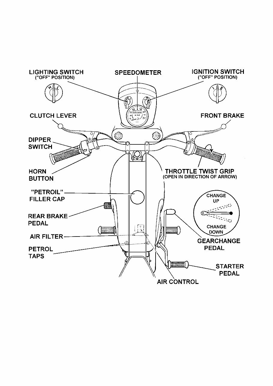
Fig. 1. The Controls (Bantam de luxe)
(Silver Bantam similar except in detail)
3

CONTENTS
AIR CLEANER . . . . . . . . . . . . . .
BRAKES . . . . . . . . . . . . . . . .
CARBURETTER . . . . . . . . . . . . . .
FRONT CHAIN . . . . . . . . . . . . . .
REAR CHAIN . . . . . . . . . . . . . .
CLEANING . . . . . . . . . . . . . .
CLUTCH . . . . . . . . . . . . . . . .
CONTROLS . . . . . . . . . . . . . .
CYLINDER HEAD AND BARREL REMOVAL . . . .
DRIVING . . . . . . . . . . . . . . . .
DECARBONISING . . . . . . . . . . . .
ELECTRICAL EQUIPMENT . . . . . . . . . .
FORKS . . . . . . . . . . . . . . . .
GEARBOX . . . . . . . . . . . . . . . .
HUBS . . . . . . . . . . . . . . . .
IGNITION TIMING . . . . . . . . . . . .
LUBRICATION CHART . . . . . . . . . .
LUBRICATION (ENGINE) . . . . . . . . . .
ROUTINE MAINTENANCE . . . . . . . . . .
REAR SUSPENSION . . . . . . . . . . . .
RUNNING-IN . . . . . . . . . . . . . .
SPARKING PLUG . . . . . . . . . . . .
STEERING HEAD . . . . . . . . . . . .
TECHNICAL DATA . . . . . . . . . . . .
TRANSMISSION . . . . . . . . . . . . . .
WHEEL REMOVAL (FRONT) . . . . . . . .
WHEEL REMOVAL (REAR) . . . . . . . . . .
WIRING DIAGRAM . . . . . . . . . . . .
19
25
17
22
22
11
23
7
14
8
14
27
26
24
24
13
20, 21
12
11
27
10
16
27
5, 6
22
24
24
31
4
pages

TECHNICAL DATA
Engine Number—on top of crankcase below cylinder.
Frame Number—at top of steering head tube.
Engine:
Capacity . . . . . . . . . . . . . . . . . .
Cylinder bore . . . . . . . . . . . . . . . .
Stroke . . . . . . . . . . . . . . . . . .
Compression ratio . . . . . . . . . . . . . . . .
Piston ring gap . . . . . . . . . . minimum
maximum
Sparking plug . . . . . . . . . . . . . . . .
Plug points gap . . . . . . . . . . minimum
maximum
Contact breaker points gap . . . . . . . . . . . .
174 c.c.
61·5 mm.
58 mm.
7·4—1
·009 in.
·013 in.
L7
·020 in.
·025 in.
·015 in.
Transmission:
Gear ratios . . . . . . . . . . . . . . top
second
first
6·58
9·26
17·4
Clutch—friction plates . . . . . . . . . . . . . . 3
Chain size and pitch
front ⅜ × ·250 in. . . . . . . . . . . . . . .
rear ½ × ·335 in. roller . . . . . . . . . . . .
50 pitches
120 pitches
Teeth on: engine sprocket . . . . . . . . . . . . 17
gearbox sprocket . . . . . . . . . . . .
clutch sprocket . . . . . . . . . . . . . .
rear chainwheel . . . . . . . . . . . .
16
38
47
Capacities:
Fuel tank . . . . . . . . . . . . . . . . . .
Petroil mixture . . . . . . . . . . . . . . . .
Gearbox . . . . . . . . . . . . . . . . . .
Front forks . . . . . . . . . . . . . . . . . .
2 gallons
See pages 12
and 20
¾ pint
⅛ pint each
leg
Wheels:
Tyre size . . . . . . . . . . . . . .
Tyre pressure . . . . . . . . . . . .
Brake size . . . . . . . . . . . . . .
front
rear
front
rear
dia.
wide
3·00—18
3·00—18
17 p.s.i.
22 p.s.i.
5½ in.
1 in.
5

TECHNICAL DATA
Carburation: Amal
Bore . . . . . . . . . . . . . . . .
Main jet . . . . . . . . . . . . . .
Pilot jet . . . . . . . . . . . . . .
Throttle valve . . . . . . . . . . . .
Needle position . . . . . . . . . . . .
Needle jet . . . . . . . . . . . . . .
⅞ in.
140
25
375/3½
2
·1055
General Details:
Overall length . . . . . . . . . . . .
Wheelbase . . . . . . . . . . . . . .
Ground clearance . . . . . . . . . . . .
Seat height . . . . . . . . . . . . . .
Overall height . . . . . . . . . . . .
Handlebar width . . . . . . . . . . . .
79⅜ in.
51⅛ in.
5½ in.
31 in.
36 in.
27¾ in.
The recommended tyre pressures are based on a rider’s weight of 140
lbs. If the rider is heavier, increase the pressures as follows: —
Front tyre: Add one lb. Per sq. in. for every 28 lb. Increase above
140 lb.
Rear tyre: Add one lb. Per sq. in. for every 14 lb. Increase above
140 lb.
If additional load is carried in the form of a pillion passenger or
luggage, the actual load bearing upon each tyre should be determined
and the pressures increased in accordance with the Dunlop Load and
Pressure Schedule.
6

TAKING OVER THE MACHINE
Before running the machine make sure that the fuel tank contains the correct
mixture of oil and petrol, that the gearbox is properly topped up with oil and that the
battery is filled and charged. (See appropriate chapters for filling instructions).
Normally these preparations will be carried out by the dealer who is selling the
machine and the new owner has only to arrange the controls to his liking and the
machine is ready for the road.
The Controls
The new rider should make sure that he is quite familiar with all the controls before
attempting to ride the machine. Most of the controls are adjustable and should be
positioned so that they can be reached without moving the hands from the grips or the
feet from the footrests. Handlebars should be adjusted so that a comfortable and
natural riding position is achieved. Make sure that the bolts retaining the handlebar
clamps are tight after completing any adjustment. Badly positioned controls cause
poor control of the machine and will bring discomfort on long journeys.
Handlebar Controls
Twist Grip.—Mounted on the right handlebar it controls the throttle opening and
consequently the engine speed. To open the throttle (i.e. to increase the engine
speed) turn the grip so that the top moves towards the rider. Excess slackness in the
cable can be removed by means of an adjuster incorporated in the cable at the
carburetter end.
The rotary stiffness of the twist grip can be varied by means of the adjuster screw
and locknut. It is set for average requirements when leaving the factory, but can be
readjusted to suit individual preference.
Front Brake.—Lever mounted on the right handlebar in front of the throttle
control. Grip the lever gently to operate the brake.
Clutch.—The lever is mounted on the left handlebar. Grip the lever to free the
clutch, i.e. to disengage the drive between the engine and the rear wheel.
Horn.—The horn button is mounted on the left handlebar and is incorporated in the
headlight dipper switch.
Headlight Dipper Switch.—Controls the switching from main to dipped headlight
beams and is mounted on the left handlebar.
Other Hand Controls
Air Control (Carburetter).—This is operated by the spring loaded plunger above
the carburetter. Depress to give a rich mixture for starting purposes, raising
immediately afterwards.—(Important see carburetter air control, page 19).
Petrol Taps.—Under the rear end of the tank. To turn on the petrol, pull out the
serrated button and lock in position by turning anti-clockwise. To turn off the petrol,
reverse this procedure. Both taps communicate with the main supply in the tank but
if one tap is used, a reserve supply is left which can be fed to the carburetter only
when the second tap is turned on. One tap only is fitted to the Silver Bantam.
Headlight Switch.—This is operated by a switch on the headlamp, and has three
positions—OFF, LOW (L), and HEAD (H) respectively. The low position is for use
when the machine is stationary.
7

Ignition Switch.—This is mounted on the top of the headlamp and has three
positions. With the pointer straight ahead, the ignition is switched off, and the switch
should always be retained in this position when the engine is stationary, otherwise
after several hours (say, over-night) the battery may become discharged. For normal
starting, rotate the switch until the position marked “I” is straight ahead. For
emergency starting with a discharged battery, rotate the switch until position “E” is
straight ahead. (Important—See Electrical Equipment).
Carburetter Tickler.—This is a small plunger in the top of the carburetter float
chamber on the left hand side. Pressing it down pushes down the float and frees the
needle valve thus permitting the carburetter to receive excess petrol.
Steering Lock.—Provision is made for locking the steering. Turn the forks to the
left, when the hole in a special frame lug will coincide with the corresponding hole in
the bottom yoke lug. Locking the two lugs together by means of a padlock, prevents
the machine from being driven or wheeled away.
Foot Controls
Rear Brake.—On the left-hand side of the machine controls the rear brake only.
Gear-change Pedal.—On the right-hand side of the engine there are two pedals
one of which projects forward, this being the gearchange pedal. It affects the change
from one gear to another. The lever is of the positive stop type and returns to the
central position after each change. Upward movement of the lever selects the next
higher gear, downward a lower gear. Neutral is between first and second gear.
Starter Pedal.—This is the other pedal on the right-hand side of the engine.
Depression of the pedal rotates the engine.
Instruments
Speedometer.—This is mounted centrally in the headlight body and records speed
and total mileage.
DRIVING
To Start the Engine
Turn the ignition switch to the position marked “I” (see “Controls”). It will be
impossible to start the engine until this has been done.
Stand astride the machine and make sure that the gears are in the neutral position,
which lies between the first and second gears. If there is any doubt about this,
depress the gearchange pedal fully two or three times to engage successively lower
gears, at the same time easing the machine backwards and forwards to allow the gears
to rotate a little, and so facilitate gear engagement. When it is certain that first gear is
obtained, raise the pedal by half its normal stroke, so selecting the neutral position.
Should the machine be in gear it will move forward as the starter pedal is depressed.
If the engine is quite cold, depress the carburetter tickler momentarily. Note that it
is neither necessary nor desirable to oscillate the tickler rapidly, as this may damage
the float. Close the carburetter air control, thus giving a rich mixture for starting (see
page 19).
8

Open the twist grip a small amount only, as excessive opening may prevent easy
starting, and push the starter pedal down slowly until resistant is felt; then, without
releasing the pressure on the pedal, give a firm downward swing which should set the
engine in motion. If the engine fails to start at the first attempt, repeat this procedure,
being careful to avoid rapid kicking at the pedal which will serve no purpose and may
damage the operating mechanism.
Note that while it is necessary to use the carburetter air control when starting from
cold, this may not be necessary when the engine is warm, and should certainly not be
so if a re-start is made after a short wait only. During normal running the air control
must always be kept fully open and it should be opened immediately the engine fires,
or should the weather be cold, at the earliest possible moment.
Engaging First Gear
With the engine running slowly, disengage the clutch by gripping the left
handlebar lever and after a brief interval press down the gearchange pedal as far as it
will go, so selecting first gear. If the pedal will not move through its full travel, so
that the gear does not engage, ease the machine backwards or forwards slightly,
maintaining a light pressure on the pedal, until the gear is felt to engage.
Moving Off
Open the throttle slightly and gently release the clutch lever part way, until the
clutch can be felt to take up the drive, and the machine tends to move forward. Open
the throttle a little more to prevent the possibility of stalling the engine, and slowly
release the clutch lever as the machine moves away. Until the lever is completely
released the clutch is not fully engaged, so that the engine should not be speeded up
excessively or the clutch remain partly engaged, for longer than is necessary to get
the machine away in first gear.
Changing Gear (Up)
When the machine is moving steadily with the clutch fully engaged, the next
operation is to engage second gear. Close the throttle, disengage the clutch, and raise
the gearchange pedal as far as it will go, the three movements being performed
simultaneously. Immediately the gear is felt to engage, re-open the throttle and re-
engage the clutch. A similar procedure is necessary for each upward gearchange.
Changing Gear (Down)
Open the throttle slightly, disengage the clutch, and press the gear change pedal
down as far as it will go. Re-engage the clutch as soon as the gear is felt to engage.
Violent pressure on the gear lever is unnecessary, a steady movement of the pedal
being most effective. All downward gearchanges should be made in a similar
manner.
To Select Neutral
Neutral is situated between first and second gears. To select neutral from first
gear, withdraw the clutch and lift the gearchange pedal gently until it is felt to click
into the neutral position. If the lever is lifted up too far it will travel through to
second gear.
9
You're Reading a Preview
What's Included?
 Lifetime Access
Fast Download Speeds
Online & Offline Access
Access PDF Contents & Bookmarks
Full Search Facility
Print one or all pages of your manual
$28.99
BSA D7 175CC BANTAM Workshop Repair Manual
Viewed 11 Times Today

What's Included?
Lifetime Access
Fast Download Speeds
Online & Offline Access
Access PDF Contents & Bookmarks
Full Search Facility
Print one or all pages of your manual
$28.99

Secure transaction
What's Included?
Lifetime Access
Fast Download Speeds
Online & Offline Access
Access PDF Contents & Bookmarks
Full Search Facility
Print one or all pages of your manual
Description
The BSA D7 175CC BANTAM Workshop Repair Manual is a comprehensive guide containing all the necessary information for repairing, maintaining, rebuilding, refurbishing, or restoring your vehicle. It covers all diagnostic and repair procedures in great detail, making it useful for both professional technicians and DIY enthusiasts.
- All repair procedures are covered from A-Z
- Includes high-quality photos, illustrations, and diagrams
- Compatible with Microsoft Windows 95, 98, 98SE, 2000, NT, ME, XP, Vista, and Windows 7, as well as all Mac computers
This easy-to-use Workshop Repair Manual allows you to view and print out the complete repair procedures without requiring advanced computer skills. Say goodbye to messy manuals that wear out over time, as you can simply print the required information and start working on your vehicle.


