

BLATA B1 ORIGAMI MINI Bike Service Manual
What's Included?
Fast Download Speeds
Online & Offline Access
Access PDF Contents & Bookmarks
Full Search Facility
Print one or all pages of your manual

Downloaded from www.Manualslib.com manuals search engine

MINIBIKE – ORIGAMI B1
SERVICE MANUAL FOR USE AND MAINTENANCE AND SPARE PARTS LIST
For your own safety and the safety of others Follow these recommendations in order to use
your MINIBIKE safely and correctly. Read the instructions CAREFULLY, failure to do so may
place yourself and others in extreme and or ultimate DANGER. If you do not understand the
instructions and Data then, you are not to attempt to operate this Minibike under any
circumstances. It may be used for show purposes only!
CONTENTS
PAGE
INTRODUCTION .............................................................................................................. 2
TECHNICAL DATA .......................................................................................................... 2
UNPACKING AND SETTING UP BEFORE RIDING ....................................................... 3
SAFETY ............................................................................................................................ 3
BEFORE STARTING........................................................................................................ 3
STARTING THE ENGINE - FIG. 2 ................................................................................... 4
CARBURETOR - FIG. 3 ................................................................................................... 4
RIDING ............................................................................................................................ 4
PERIODIC MAINTENANCE ............................................................................................. 5
CHAIN SETTING AND MAINTENANCE ......................................................................... 5
CENTRIFUGAL CLUTCH REPAIR OR REPLACEMENT…............................................ 5
BRAKES ADJUSTING - FIG. 4 ........................................................................................ 6
FRONT BRAKES PADS REPLACEMENT - FIG. 7 ......................................................... 6
REAR BRAKES PADS REPLACEMENT - FIG. 7. ......................................................... 6
REMOVE AND REFIT THE FRONT WHEEL – FIG. 5 ……………................................... 7
REMOVE AND REFIT THE REAR WHEEL - FIG. 5 ................................................ ....... 7
REPLACEMENT OF SPROCKET - FIG. 9 ..................................................................... 7
MINIBIKE ORIGAMI B1 - FIG. 5 ………………………………………………….................... 8,9
PARTS LIST ……………………………………………………………………....................... 10,11
ENGINE - BLATA …………………………………………………………………................ 12
CLUTCH COMPLETE - FIG. 6…………………………………………………..................... 13
FRONT AND REAR BRAKES - FIG. 7 …………………………………………................. 14
REPLACEMENT OF TIRE – FIG. 5 ................................................................................. 15
REMOVE AND REFIT AIR FILTER .................................................................................. 15
CLUTCH ADJUSTMENT – FIG. 8 ………………………………………………................... 15
MAINTENANCE OF COOLING SYSTEM ………………………………………................. 16
TORQUE SETTINGS ......................................................................................................... 17
STORAGE PROCEEDURES …………………………………………………………............. 18
Downloaded from www.Manualslib.com manuals search engine

INTRODUCTION
The Minibike Origami B1 is designed and built for use on a paved closed circuit
track. The track should be clean and without obstacles of any kind. Qualified
adults and younger persons can drive the minibike. Children can drive the
minibike only under the supervision of a responsible adult person. The
minibike is constructed especially for racing competitions on special racing
tracks.
The minibike uses a single-cylinder two-stroke, Gasoline combustion engine,
and has an air filter and exhaust silencer. Transfer of power to the rear wheel is
through a drive chain. The the overall drive ratio to the rear wheel can be
changed by the replacement of chain sprockets. The front and rear wheel is
equipped with disk brakes. The rear brake is controlled with the left lever and
the front brake is controlled with the right lever on the handlebars.
BASIC TECHNICAL DATA
ENGINE : BLATA…………………………….………………………TWO-STROKE
NUMBER OF CYLINDERS ................................................................. 1
CYLINDER CAPACITY …………………………….. .........39,8 cc
ENGINE COOLING SYSTEM………………………..LIQUID COOLED
POWER OUTPUT ........................................... 10,5 kW at 12 300 rpm
TORQUE ………………………………................8,1 Nm at 12 000 rpm
CARBURETOR ........................................... PHVA 17,5 DELL’ ORTO
FUEL ADMISION …………REED VALVE DIRECT TO CRANKCASE
IGNITION................................................................... CONTACT-LESS
SPARK PLUG……………………..................................... NGK B9ES
STARTING ........................................... HAND PULL TYPE, MANUAL
CLUTCH ............................................... CENTRIFUGAL AUTOMATIC
FRAME : ENHANCED TRELLIS…………….. SUPPORTING STRUCTURES
MADE OF LIGHT ALLOYS
BRAKES : FRONT WHEEL ... DISC BRAKE – DISC DIAMETER 162mm ( 6,3”)
REAR WHEEL ........ DISC BRAKE-DISC DIAMETER 119 mm ( 4,7”)
WHEELS : FRONT ............................................ OF LIGHT ALLOY 2,1”x 6,5”- 99
REAR ............................................ OF LIGHT ALLOY 2,1”x 6,5”- 130
TIRE : FRONT ...................................................................... SIZE 90/65 - 6,5”
REAR .......................................................... 110/50 - 6,5”, 90/65 - 6,5”
FUEL : .........MIXTURE OF PETROL 92 OR HIGHER OCTANE +2 STROKE
SYNTHETIC OIL
MIXING RATIO (after break in period) ....................................... 50: 1
TANK CAPACITY ............................................1,7 Liter 0,44 US gal. )
UNLOADED WEIGHT : ..................................................................... 25 kg ( 55 lb. )
CARRYING CAPACITY : ............................................................... 110 kg ( 242 lb. )
BASIC DIMENSIONS:
LENGTH .................................................................... 1 100 mm ( 41” )
WIDTH ......................................................................... 560 mm ( 22 “ )
HEIGHT ..................................................................... 550 mm ( 21,6” )
Downloaded from www.Manualslib.com manuals search engine
UNPACKING AND SETTING UP BEFORE RIDING
The minibike is delivered in a cardboard carton and packed with folded
handlebars and brake levers. After unpacking, set up the handlebars into the
position, that suits the best for driving. The maximum pulled brake lever
position should not touch on the handlebar grip. After setting up, tighten the
handlebar sleeve (clip-on) nuts 1; tighten the brake lever bolts and the throttle
assembly 3. See, Fig.1. By loosening the nut M8 (P/N 920.010.01) on the foot
peg bracket, the rider can adjust the foot peg position in a forward or rear
direction. The foot rest can be moved to the front or back position. It is
recommended to try and check the position of handlebars and foot rests
individually. While tightening the bolts and nuts, do not use an excessive force
as to not damage the threads, or distort the tubes and other parts. Verify the
smooth and perfect function of the Bowden cables to throttle and both brakes.
Fill the cooling system with coolant and vent the system (follow the
instructions in chapter MAINTENANCE OF COOLER SYSTEM). Fill the fuel
tank with fuel mixture. Failure to use the proper oil mix ratio will result in
Engine damage for which you will be responsible.
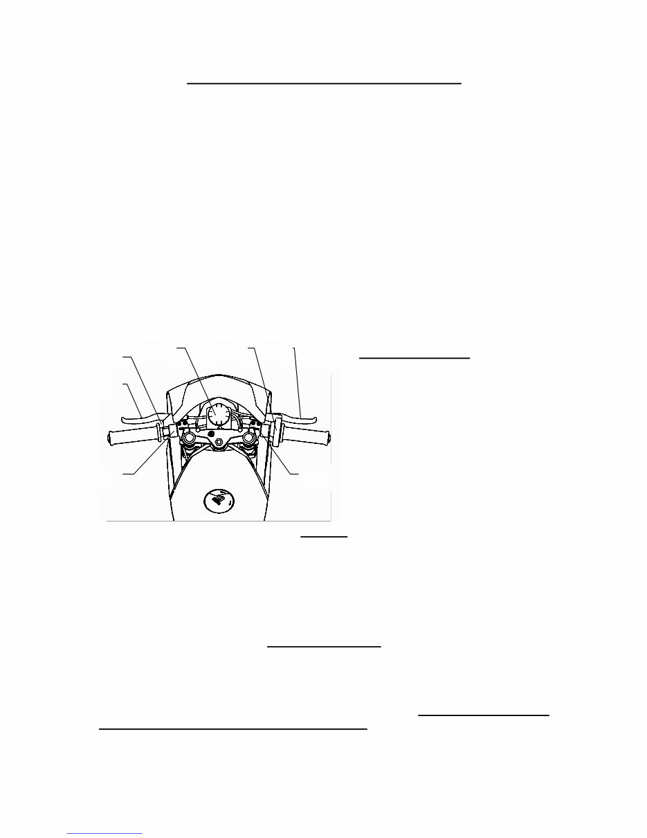
Fig. 1
Operating controls:
1. Handlebar bolts
2. Brake lever bolts
3. Throttle Assy. bolts
4. Stop switch
5. Front brake lever
6. Rear brake lever
7. Balance tank for coolant
Range of adjusting handlebars
function position
SAFETY
The minibike is unsuitable for public road use. It does not comply with valid
Safety Standards. Unsafe and careless use of a minibike can result in serious
injuries. The driver can minimize the potential risks by wearing the Safety
Equipment. The driver must wear safety helmet, goggles, gloves, elbow pads,
kneepads, and firm footwear. The minibike cannot be used on wet, icy or oily
surfaces. Avoid uneven surfaces and obstacles. Drive with two hands on the
handlebars.
BEFORE STARTING
It is strongly recommended to follow all the instructions about the break-in
period to promote engine reliability and long life. Break-in period of the
minibike is complete after the consumption of five full fuel tanks. It is important
to use mixture of petrol 92 or higher Octane with 2-stroke synthetic oil in the
ratio 30:1 and after break-in period a ratio of 50:1. Mix the petrol and oil
completely before putting it into the fuel tank. During the break-in period do
not run the engine at maximum RPM and do not allow the engine to overheat.
1
6
4
2
7 3 5
Downloaded from www.Manualslib.com manuals search engine
Check the tire inflation – 200 kPa (2 bars) or (28 to 30psi) to be commensurate
with the driver’s weight. The Tyre pressure should never exceed 2,5 bars,
(38psi) in either the front or rear wheel.
IMPORTANT NOTICE: If the coolant level rises in the balance tank, switch off
the engine immediately! Check the drive of the coolant pump and sealing of the
cooling system. After these steps, execute the ventilation of the Radiator. The
raised level of coolant is an indicator of a overheated engine, which can result
in seizing the piston in the cylinder.
STARTING THE ENGINE
Engine starting should be done only on the stand - Fig. 2. Fill the fuel tank and
close it with the filler cap. Open the Gas petcock. Set the petrol supply cock.
Set the choke lever into position “C”, Fig. 3. Without turning the accelerating
handle, pull gently twice the starting wire and by next guick pull start the
engine. It is not allowed to pull the starting wire up to full winding off. The
choke lever will turn back to the position “A” automaticaly by turning the
accelerating lever after a short engine run . Let the engine run about 1 min.
Leave the minibike on the stand with running engine and if necessary adjust
the revolutions so the rear wheel is not turning. For adjustment use the
adjustment screw No. 3 on the carburetor Fig. 3.
Fig. 2
CARBURETOR
1. Air filter
2. Carburetor body
3. Idle speed adjusting screw
4. Float chamber
A – Cock position for riding
C – Cock position for cold starting
Fig. 3
RIDING
Remove the minibike from the stand to sit on the seat. When seated, then
slowly rotate the throttle grip to start riding. Before braking, rotate the Throttle
grip to the off or idle position and lightly depress the rear brake lever with left
hand and then the front brake lever with right hand. Beware to not skid the
wheels. The minibike engine is switched off by pushing the red button (Engine
stop switch) on the handlebars. It is necessary to check the tightness of bolts
and nuts, especially of the engine, and the brake settings after the first ride and
often during the break in period.
1 2
4
3
C
A
Downloaded from www.Manualslib.com manuals search engine

PERIODIC MAINTENANCE
Periodic maintenance is the best way to help the machine perform well, give
longevity and provide safety and low cost operation. In addition, you will be
spared from many worries from self caused problems, resulting from poor
maintinence or no maintinence.
A - Before every ride:
1. Check the Cables and efficiency of brakes.
2. Check the lubrication and chain tension settings. The chain free play should
be (5 mm) (.200in) After every ride clean the minibike carefully and keep it
clean. Do not use aggressive cleaning detergents.
3. After 1-hour of use, wash the air filter in air drying spirits and lubricate it
with special oil for air filters.
4. After 1- hour of use, check the state of the clutch pads. Review the clutch
adlustment.
B. After every 5 hours of riding:
Check the tightness of all bolts and nuts. Tighten with a properly adjusted
torque wrench only! For torque settings see tables on page 17.
5. Wash the air filter in gas and lubricate it with special oil for an air filters to
better catch the dust.
6. Clean carefully the carburetor float chamber.
7. Check the brake pads, the thickness of brake lining cannot be less than 1
mm (.039 in). Review the basic brake adjustment.
8. Check the state of the clutch pads - the thickness cannot be less than 1 mm
(.039in). Review the clutch adjustment.
C - Every time after 10 hours of riding:
9. Check the state of the clutch pads - the thickness cannot be less than 1 mm
(.039in).
CHAIN SETTING AND MAINTENANCE
To set the chain tension, loosen the Nut (920.011.01) of the axel thru the rear
wheel and the nut (914.021.01) of the rear Caliper anchor plate. The required
chain tension (chain free play ) is (5 mm) (.200in) and is performed by equal
movement of the Axel adjustor plate (920.009.01) on the both sides of the rear
wheel. When the adjustment is correct, tighten the Axel nuts and the Caliper
holding nut. Tighten the adjustor plate nuts both sides an extra nip, just to set
them firmly. It is important to lubricate the chain regularly, to avoid excess
wear and prolong effective lifetime. The lubrication is important after every ride
on a wet surface. It is recommended to lubricate the minibike with special
chain spray. If chain replacement is necessary, check both chain Sprockets
and if there is a need to change them do it together with the chain.
CENTRIFUGAL CLUTCH PARTS, REPLACEMENT
Remove the chain guard by loosing two bolts M6 (916.020.01), Fig. 5. Loosen
the chain and remove it from the sprocket. Next, loosen three bolts holding the
aluminum clutch housing. Remove it together with steel clutch basket, and
dismantle it. Loosen the bolt from the carrier and remove the clutch from the
engine. Loosen and remove the adjustable bolts and springs. Then dismantle
the safety rings from pins. When all this is done, replace with new clutch
slipper shoes and springs (if required), at this time. During the reassembly
process follow these steps: 1. put the plate with the springs on the slipper
shoes. 2. Put the plate against the carrier and mount it on the fixed pins.
Fit it with the safety rings and install the adjustable bolts.
Downloaded from www.Manualslib.com manuals search engine
ADJUSTING THE BRAKES
Small incremental brake adjustment
Free play at the handlebar lever is effected by turning the knurled end on the
cable adjustor. This will allow the lever to be set at the nominal to ¼ inch of
free lever movement.
Basic brake adjusting:
Screw in the knurled cable adjustor at the brake lever so the cable is in it’s
most slack starting position.. At the caliper, loosen the nut, No. 3 and tighten
the adjustable bolt No. 4 , so the wheel cannot turn. Back off bolt No. 4 about ¼
to ½ of a turn and fix it with lock nut No. 3 . Do not use the cable retainer No. 5
for adjusting the brakes!
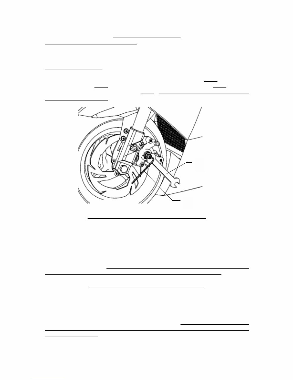
Fig. 4
FRONT BRAKE PADS REPLACEMENT - FIG. 7
First screw in the knurled cable adjustor at the right brake lever (122.002.00) on
the handlebars to the starting position (slackened cabled). Loosen the nut
(920.001.01) and turn the adjustable bolt (512.015.00) in the way that by
pressing the front brake lever, the lever (312.017.00) will be over the bolt head
M5 (312.018.00), which protects brake pads and spring of pads (312.020.00).
Unbolt this bolt and replace the old brake pads with new ones. When mounting
the brake pads place the brake spring against both pads, so they are pressed
into the front direction. While replacing the brake pads do not loosen bolts M5
(914.001.01) on the driving pins and do not loosen the cable retainer!
REAR BRAKE PADS REPLACEMENT - FIG. 7
First screw in the knurled cable adjustor at the left brake lever (122.001.00) on
the handlebars to the starting position (slackended cable). Loosen the nut
(920.001.01) and turn the adjustable bolt (512.015.00) all the way out. Unbolt the
nut M10 (920.001.01) of the back axel, push it out and dismantle the rear wheel
from the Swingarm. Push out the brake from driving pins, that will loosen the
brake pads and replace the old ones at this time. While replacing the brake
pads do not loosen bolts M5 (914.001.01) on the driving pins and do not loosen
the cable retainer! During the mounting follow all these instructions in the
reverse direction and then perform basic adjusting of the brakes.
4
3
Downloaded from www.Manualslib.com manuals search engine
REMOVE AND REPLACE THE FRONT WHEEL - FIG. 5
Before dismantling the front wheel it is necessary to remove the front brake
pads from the front brake, so it is possible to move the brake caliper from the
wheel and be able to draw out the wheel and tire. Remove the front axel nut.
M10 (920.011.01) Draw out the axel from the fork and wheel. Remove the wheel
by an easy pull downwards from the forks. CAUTION! Two 3mm spacers will
fall out when the wheel is being removed! Insert one spacer between the brake
rotor and the brake mounting bracket, and the other spacer between the wheel
and the right fork (P/N 315.011.00) when re-assembling. Return the brake pads
with the spring and tighten up the axel nut. Perform the basic brake adjusting.
Double check your work. This is important!
REMOVE AND REPLACE THE REAR WHEEL - FIG. 5
Loosen and remove nut M10 on the rear axle. Safely (hold) keep the rear wheel
from falling out while pulling out the axel. Caution, note the location of both
spacer tubes and one spacer washer (between caliper mount plate and rotor)
while removing wheel. When refitting the wheel, make sure to slide the brake
rotor into the caliper between the pads. Hold the wheel in place and fit the
wheel spacers in proper order. . Insert one 3mm spacer between the brake
rotor and brake mounting bracket and than insert the 9.5mm spacer between
the brake and the rear swing arm. Adjust chain tension and tighten axel nut.
Tighten the caliper holder plate nut and set and tighten both chain adjustor
plate M6 nuts. At this time check the brake operation. Recheck all your work.
This is important !
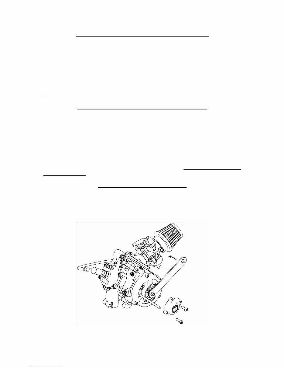
REPLACEMENT OF PINION - FIG. 9
First dismantle the front chain guard and chain guard.Loosen the nut of rear
wheel axle and the nut of chain tightener ,remove chain. Insert carefully a
larger screw driver or steel rod into the hole of clutch drum, Fig. 9, to avoid a
turning over the clutch drum at releasing the pinion. Using the pinion wrench
P/ N 319.050.00, release the new pinion to be carried out by reverse way.
FIG. 9
Downloaded from www.Manualslib.com manuals search engine
REPLACEMENT OF TIRE – FIG. 5
Remove the wheel from the minibike. For the front wheel unbolt the brake disk
and for the rear wheel, the brake disk and sprocket. Deflate the tire, by
removing the valve stem. Place the wheel on a hard surface and press the tire
bead from the wheel rim in to the middle relief at centre of rim. Tire is ready to
be removed from the rim at this time and is done in the conventional manner.
After fitting new Tire and Tube (if necessary) to the rim, you can inflate 28 to 30
psi. Take care to check that the tire bead is fully seated in the rim bead edge.
You can now refit the wheel to the bike in reverse order to removing it. Use
Caution and recheck your work always.
DISMANTLING AND MOUNTING OF AIR FILTER - FIG. 3
Remove the bolt from the sleeve, which connects the rubber holder of the air
filter to the carburetor. When the air filter is loosened, take it out and very
carefully wash it in air drying solvent, lubricate it when dry and spray with air
filter oil and reassemble, following the steps in the reverse order.
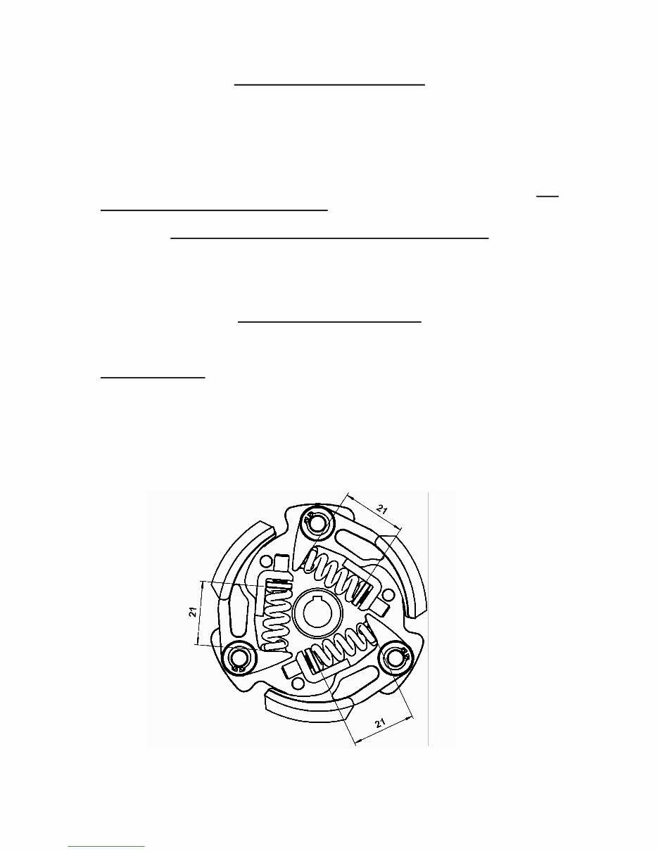
CLUTCH ADJUSTMENT – FIG. 8
After first hour of use, check the state of the clutch pads. Review the clutch
adjustment – engaged with 8 000 – 8 500 rpm.
Basic adjustment:
After every clutch slipper shoe replacement it is necessary to adjust the clutch
springs. To increase the revolutions, and feel the clutch working, tighten up
the adjusting bolts and to engage shoes at lower revolutions,loosen the bolt. It
is important to adjust all the springs to the same level, so the clutch lining
wearing is even. The index for adjusting is the length of the spring, which
should be 21,00 mm. The length is measured from the bearing surface of the
clutch shoe to the spring plate.
FIG. 8
Downloaded from www.Manualslib.com manuals search engine

MAINTENANCE OF COOLER SYSTEM
1. Liquid filling:
Place the minibike on the stand. Dismantle the seat and very carefully check all
the joints on the hose. For older minibikes do not forget to check for holes and
other damages to the hose. To fill the cooler system, 0.5 liters of the coolant is
needed. In case the minibike will be used during the wintertime, do not forget
to use the anti-freeze coolant. Pour the coolant into the balance tank, which is
placed between the handlebars, until it is filled to ¾ of capacity. Unbolt vent
bolt M5 (P/N 914.006.01), which is inserted in the hose (P/N 349.) between the
bottom part of the radiator and the engine block. Tighten the bolt only after all
air has been bled and only coolant is coming out of the vent plug hole. Always
hold the hose in order not to pull out the air escape valve. It is important to
have more than ½ capacity of the coolant in the balance tank. The same
procedure applies to the venting hose (P/N 349.) between the cylinder head and
the radiator. Once more vent the system while loosening the air bleed screws
until all air is expelled.
Close the tank and pull the start T’handle two or three times. This will circulate
the coolent in the system. Once more vent the system while loosening the air
bleed screw.
Only now it is possible to start the minibike, and leave it to run on the stand for
one minute. Turn of the motor, and vent it again. Then the minibike is ready for
use.
2. Check up of cooler system:
Before every ride check the amount of coolant in the balance tank! After every
10 hours of riding, remove the pull starter cover and check the Gilmer type
belt, which runs the coolant pump.
Important notice: If the coolant level rises in the balance tank switch of the
engine immediately! Check the drive of the coolant pump and sealing of the
cooler system. After these steps vent the air bleed screw. The raised level of
coolant is an indicator of a warmed up engine, which can result in seizing of
the piston in the cylinder.
3. Draining the Coolant:
Dismantle the hose on the bottom of the cooler system and eliminate the
liquid. Unbolt the drain plug in the balance tank.
Downloaded from www.Manualslib.com manuals search engine
You're Reading a Preview
What's Included?
Fast Download Speeds
Online & Offline Access
Access PDF Contents & Bookmarks
Full Search Facility
Print one or all pages of your manual
$31.99
Viewed 89 Times Today


Secure transaction
What's Included?
Fast Download Speeds
Online & Offline Access
Access PDF Contents & Bookmarks
Full Search Facility
Print one or all pages of your manual
$31.99
SERVICE MANUAL FOR USE AND MAINTENANCE AND SPARE PARTS LIST
- INTRODUCTION
- TECHNICAL DATA
- UNPACKING AND SETTING UP BEFORE RIDING
- SAFETY
- BEFORE STARTING
- STARTING THE ENGINE - FIG. 2
- CARBURETOR - FIG. 3
- RIDING
- PERIODIC MAINTENANCE
- CHAIN SETTING AND MAINTENANCE
- CENTRIFUGAL CLUTCH REPAIR OR REPLACEMENT
- BRAKES ADJUSTING - FIG. 4
- FRONT BRAKES PADS REPLACEMENT - FIG. 7
- REAR BRAKES PADS REPLACEMENT - FIG. 7
- REMOVE AND REFIT THE FRONT WHEEL FIG. 5
- REMOVE AND REFIT THE REAR WHEEL - FIG. 5
- REPLACEMENT OF SPROCKET - FIG. 9
- MINIBIKE ORIGAMI B1 - FIG. 5
- PARTS LIST
- ENGINE - BLATA
- CLUTCH COMPLETE - FIG. 6
- FRONT AND REAR BRAKES - FIG. 7
- REPLACEMENT OF TIRE FIG. 5
- REMOVE AND REFIT AIR FILTER
- CLUTCH ADJUSTMENT FIG. 8
- MAINTENANCE OF COOLING SYSTEM
- TORQUE SETTINGS
- STORAGE PROCEEDURES


