RS 250 9 - 129 DESMONTAJE DISCO FRENO Lea con cuidado pág. 9-15 (PRECAUCIONES E IN- FORMACIONES GENERALES). ◆ Extraiga la rueda trasera, véase pág. 9-113 (DES- MONTAJE RUEDA COMPLETA). Para destornillar los tornillos (1) se aconseja utilizar una pistola atornilladora de aire que dará un golpe seco desbloqueando la acción del LOCTITE ® 243. ◆ Destornille y quite los cinco tornillos disco freno (1). Par de apriete tornillos disco freno (1): 25 Nm (2,5 kgm) + LOCTITE ® 243. Durante la reinstalación aplique LOCTITE ® 243 en la rosca de los tornillos dis- co freno. Durante la reinstalación atornille todos los tornillos manualmente y apriételos actuando en diagonal siguiendo el orden: A-B-C-D-E. ◆ Extraiga el disco freno (2). DESMONTAJE BOMBA FRENO Maneje con cuidado el líquido: altera química- mente la pintura y las partes de plástico, go- mas, etc. NO ESPARZA EL LÍQUIDO EN EL AMBIENTE ◆ Quite el casquillo protector de goma. ◆ Introduzca un tubo de plástico transparente en la vál- vula de purga (3) de la pinza e introduzca la otra extre- midad del tubo en un recipiente de recogida. ◆ Afloje la válvula de purga (3) más o menos de una vuelta. ◆ Cuando todo el líquido habrá salido, destornille y quite el tornillo (4) y guarde las dos arandelas de estanquei- dad. Par de apriete tornillo (4): 20 Nm (2kgm). ◆ Afloje y desplace la abrazadera (5). ◆ Extraiga el tubo (6) del empalme en la bomba. ◆ Destornille y quite los dos tornillos (7). Par de apriete tornillos (7): 12 Nm (1,2 kgm). ◆ Saque la bomba (8) extrayéndola hacia adelante. De no resultar necesario, evite desmontar la articulación desde el pedal freno. Si ya se ha desmontado la articulación, al reinstalarla aplique LOCTITE ® 270 en la rosca y apriete completa- mente. Durante la reinstalación efectúe el relleno lí- quido freno, véase pág. 2-30 (FRENOS) y la purga aire sistema de frenado, véase pág. 2-34 (PUR- GA DEL AIRE DESDE EL CIRCUITO HIDRÁULICO DE LOS FRENOS). REMOVING THE BRAKE DISC Carefully read p. 9-16 (PRECAUTIONS AND GENER- AL INFORMATION). ◆ Remove the rear wheel, see pág. 9-113 (REMOVING THE WHOLE WHEEL). To unscrew the screws (1), it is advisable to use a pneumatic screwer to release them from the LOCTITE ® 243. ◆ Unscrew and remove the five brake disc screws (1). Brake disc screw (1) driving torque: 25 Nm (2.5 kgm) + LOCTITE ® 243. Upon reassembly, apply LOCTITE ® 243 on the thread of the brake disc screws. Upon reassembly, screw all the screws manu- ally and tighten them proceeding in the diago- nal direction and in the following order: A-B-C-D-E. ◆ Remove the brake disc (2). REMOVING THE BRAKE PUMP. Handle the fluid with care: it chemically alters paints, plastic parts, rubber, etc. DO NOT DISPOSE OF THE FLUID IN THE ENVIRONMENT ◆ Remove the rubber protection cap. ◆ Insert a transparent plastic pipe in the caliper air valve (3) and insert the other end of the pipe in a container. ◆ Loosen the air valve (3) by giving it approximately one turn. ◆ When all the fluid has flown out, unscrew and remove the screw (4) and take the two sealing washers. Screw (4) driving torque: 20 Nm (2 kgm). ◆ Loosen and move the pipe clamp (5). ◆ Withdraw the pipe (6) from the coupling on the pump. ◆ Unscrew and remove the two screws (7). Screw (7) driving torque: 12 Nm (1.2 kgm). ◆ Remove the pump (8) by withdrawing it in the forward direction. Avoid removing the joint from the brake pedal, unless it is absolutely necessary. If the joint has been removed, upon reassembly apply LOCTITE ® 270 on the thread and tighten thoroughly. Upon reassembly, top up the brake fluid, see p. 2-30 (BRAKES) and bleed the braking sys- tem, see p. 2-34 (BLEEDING THE BRAKE HYDRAULIC CIRCUIT).
9 - 130 RS 250
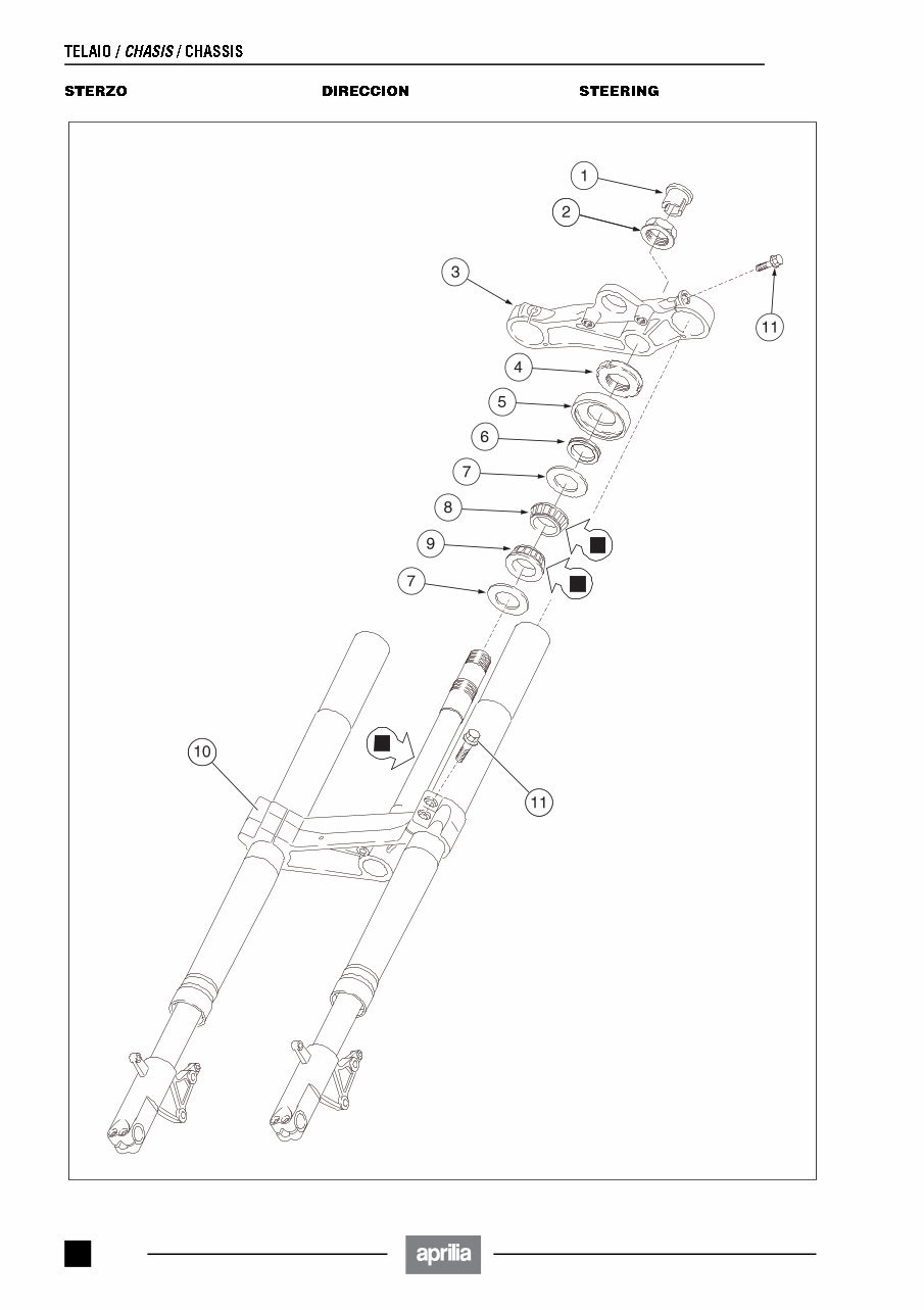
RS 250 9 - 131 Pie de la ilustración 1) Tapón superior 2) Tuerca superior dirección 3) Placa superior 4) Tuerca de regulación dirección 5) Guardapolvo 6) Distanciador 7) Retenes 8) Cojinete 9) Cojinete 10) Placa inferior 11) Tornillos sujeción tijas ■ = GRASA, véase pág. 9-20 (TA- BLA DE LUBRIFICANTES) Key 1) Upper plug 2) Steerin upper nut 3) Upper plate 4) Steering adjustment metal ring 5) Antidust gasket 6) Spacer 7) Seals 8) Bearing 9) Bearing 10) Lower plate 11) Plate fastening screws ■ = GREASE, see pág. 9-20 (LU- BRICANT CHART) Legenda 1) Tappo superiore 2) Dado superiore sterzo 3) Piastra superiore 4) Ghiera di registro sterzo 5) Parapolvere 6) Distanziale 7) Guarnizioni di tenuta 8) Cuscinetto 9) Cuscinetto 10) Piastra inferiore 11) Viti fissaggio piastre ■ = GRASSO, vedi pag. 9-19 (TA- BELLA LUBRIFICANTI)
RS 250 9 - 133 DESMONTAJE DIRECCIÓN Lea con cuidado pág. 9-15 (PRECAUCIONES E IN- FORMACIONES GENERALES) y véase pág. 9-130 (DI- RECCION). ◆ Coloque el vehículo sobre el caballete de soporte cen- tral sobre una plataforma de elevación con la rue- da delantera que sobresalga del borde de la platafor- ma. ◆ Levante la plataforma de elevación de unos 230 mm. Maneje con cuidado el líquido: altera química- mente la pintura y las partes de plástico, go- mas, etc. NO ESPARZA EL LÍQUIDO EN EL AMBIENTE ◆ ★ Quite el casquillo protector de goma. ◆ ★ Introduzca un tubo de plástico transparente en la válvula de purga (1) de la pinza e introduzca la otra ex- tremidad del tubo en un recipiente de recogida. ◆ ★ Afloje la válvula de purga (1) más o menos de una vuelta. ◆ Cuando todo el líquido habrá salido, destornille y quite el tornillo (2) y guarde las dos arandelas de estanquei- dad. Par de apriete tornillo (2): 20 Nm (2 kgm). Para realizar las operaciones que siguen a continuación no es necesario desmontar la cúpula, sin embargo se aconseja hacerlo para mover- se más libremente, véase pág. 9-103 (DESMONTAJE CÚPULA). ◆ ★ Destornille y quite el tornillo (3) que fija el semimani- llar (4) en la tija superior (5). ◆ ★ Destornille del todo el tornillo (6) que fija la tija supe- rior (5) en la horquilla delantera. ◆ Extraiga el tapón superior (7). ◆ Desenrosque y quite la tuerca superior (8). ◆ Extraiga desde arriba la tija superior (5) completa de interruptor de encendido/seguro de dirección. ◆ Doble hacia adelante la tija (5) interponiendo un trapo para no dañar el salpicadero. A causa del peso del tren delantero, las opera- ciones que siguen a continuación necesitan la intervención de un segundo operador. Pónga- se antes de acuerdo sobre las operaciones a realizar. La operación de desmontaje hay que realizarla po- niendo mucho cuidado. Soporte el tren delantero para que no caiga accidentalmente. ◆ Mientras un operador mantiene en posición el tren de- lantero, afloje la tuerca de ajuste (9). Durante la fase de desmontaje del tren delan- tero ponga cuidado en que los tubos líquido frenos no se enreden. ◆ Extraiga el tren delantero del manguito de la dirección. ◆ Guarde según el orden: – Tuerca de regulación (9) – Guardapolvo (10) – Separador (11) – Retén (12) – Cojinetes (13) – Retén (14) Lave todos los componentes con detergente limpio. DISASSEMBLING THE STEERING Carefully read p. 9-16 (PRECAUTIONS AND GENER- AL INFORMATION) and p. 9-130 (STEERING). ◆ Position the vehicle on the appropriate centre support stand on a lifting platform, with the front wheel pro- truding from the platform edge. ◆ Raise the lifting platform to a height of approx. 230 mm. Handle the fluid with care: it chemically alters paints, plastic parts, rubber, etc. DO NOT DISPOSE OF THE FLUID IN THE ENVIRONMENT ◆ ★ Remove the rubber protection cap. ◆ ★ Insert a transparent plastic pipe in the caliper air valve (1) and insert the other end of the pipe in a con- tainer. ◆ ★ Loosen the air valve (1) by giving it approximately one turn. ◆ When all the fluid has flown out, unscrew and remove the screw (2) and take the two sealing washers. Screw (2) driving torque: 20 Nm (2 kgm). To carry out the following operations it is not necessary to remove the front part of the fair- ing, but it is advisable to do it in order to have more freedom of movement, see pág. 9-103 (REMOVING THE FRONT PART OF THE FAIRING). ◆ ★ Unscrew and remove the screw (3) that fixes the half-handlebar (4) to the upper plate (5). ◆ ★ Completely unscrew the screw (6) that fixes the up- per plate (5) to the front fork. ◆ Remove the upper plug (7). ◆ Unscrew and remove the upper nut (8). ◆ Withdraw the upper plate (5) complete with ignition switch / steering lock from above. ◆ Bend the plate (5) forward, interposing a cloth in order to avoid damaging the dashboard. Due to the weight of the front part of the vehi- cle, the following operations must be per- formed by two persons. Fix the operating pro- cedure before starting work. The removal must be carried out very carefully. Support the front part of the vehicle, in order to prevent it from accidentally falling down. ◆ While one of the two operators keeps the front part of the vehicle in the correct position, the other must loos- en the adjusting metal ring (9). During the removal of the front part of the ve- hicle, take care to prevent the brake fluid pipes from getting entangled. ◆ Withdraw the front part of the vehicle from the steering tube. ◆ Take the following components, in the given order: – Adjusting metal ring (9) – Antidust gasket (10) – Spacer ring (11) – Seal (12) – Bearings (13) – Seal (14) Wash all the components with a clean deter- gent.
RS 250 9 - 135 CONTROL COMPONENTES COJINETES Véase pág. 9-115 (CONTROL COMPONENTES, COJI- NETES). JUNTAS Véase pág. 9-115 (CONTROL COMPONENTES, RETE- NES). REINSTALACIÓN DIRECCIÓN ◆ Extienda una capa de grasa lubricante sobre toda la longitud del eje dirección (1), véase pág. 9-20 (TABLA DE LUBRIFICANTES). Durante la reinstalación actúe en sentido con- trario al desmontaje. ◆ Antes de apretar definitivamente la tuerca de regula- ción (2), gire distintas veces, en los dos sentidos, el manillar para que los cojinetes se coloquen correcta- mente. ◆ Siga adelante ajustando el juego de los cojinetes, véa- se pág. 9-37 (AJUSTE JUEGO COJINETES). ◆ Girando el manillar controle que los cables y los tubos no vayan en tensión y que los mismos no se enreden y/o no se sobrepongan de manera incorrecta. ◆ Efectúe el relleno líquido frenos, véase pág. 2-30 (FRENOS). ◆ Efectúe la purga aire sistema de frenado, véase pág. 2-34 (PURGA DEL AIRE DESDE EL CIRCUITO HI- DRÁULICO DE LOS FRENOS). CHECKING THE COMPONENTS BEARINGS See p. 9-115 (CHECKING THE COMPONENTS, BEAR- INGS). GASKETS See p. 9-115 (CHECKING THE COMPONENTS, SEALS). REASSEMBLING THE STEERING ◆ Spread a layer of lubricating grease on the whole length of the steering pin (1), see p. 9-20 (LUBRICANT CHART). For the reassembly, carry out the operations described for the disassembly in the reverse order. ◆ Before definitively tightening the adjusting metal ring (2), turn the handlebar repeatedly in both directions, in order to ensure the setting of the bearings. ◆ Adjust the bearing tightness, see p. 9-37 (ADJUSTING THE BEARING TIGHTNESS). ◆ Turning the handlebar, make sure that the cables and pipes are not stretched and that they are neither crossed, nor twisted incorrectly. ◆ Top up the brake fluid, see p. 2-30 (BRAKES). ◆ Bleed the braking system, see p. 2-34 (BLEEDING THE BRAKE HYDRAULIC CIRCUIT).
The 1994-2008 Aprilia RS250 Service & Repair Manual is an official factory service reference created exclusively for the Aprilia RS250. This comprehensive manual is designed to provide thorough service and repair information, covering each model year from 1994 through 2008:
Aprilia RS 250 1994 Service Repair Manual
Aprilia RS 250 1995 Service Repair Manual
Aprilia RS 250 1996 Service Repair Manual
Aprilia RS 250 1997 Service Repair Manual
Aprilia RS 250 1998 Service Repair Manual
Aprilia RS 250 1999 Service Repair Manual
Aprilia RS 250 2000 Service Repair Manual
Aprilia RS 250 2001 Service Repair Manual
Aprilia RS 250 2002 Service Repair Manual
Aprilia RS 250 2003 Service Repair Manual
Aprilia RS 250 2004 Service Repair Manual
Aprilia RS 250 2005 Service Repair Manual
Aprilia RS 250 2006 Service Repair Manual
Aprilia RS 250 2007 Service Repair Manual
Aprilia RS 250 2008 Service Repair Manual
This manual is fully bookmarked and searchable for easy navigation, and it is the identical Repair Service manual used by local dealers when performing repairs. The PDF files are authentic, not scans, ensuring high-quality, reliable reference material.
The manual provides detailed technical information on:
General Information
Periodic Maintenance and Tune-Up Procedures
Engine
Fuel and Lubrication System
Cooling System
Electrical System
Chassis
Servicing Information
Updates
All pages are printable, making the manual ideal for use in the home, office, or repair shop. For any manual-specific inquiries or further information, please feel free to contact us via email. Upon completion of your secure payment using any major credit/debit card or PayPal, you will receive immediate access to this manual with no shipping costs or delays.
Additional resources, including Car Wiring Diagrams, Repair Manuals, Auto Service Manuals, Motorcycle Repair Manuals, Owners Manuals, Manual Printing, Free Service Manuals, Car Wiring Schematics, and Online Auto Repair Manuals, are also available.



 Lifetime Access




