CHASSIS NUTS AND BOLTS 1 ENGINE 3 LUBRICATION SYSTEM 18 FUEL SUPPLY SYSTEM 22 TRANSMISSION COMPONENTS 27 ELECTRICAL STARTING SYSTEM 30 BELT DRIVE CVT MECHANISM 36 CLUTCH 40 REAR TRANSMISSION SYSTEM 45 ELECTRICAL SYSTEM 50 IGNITION SYSTEM 56 TABLE OF CONTENTS
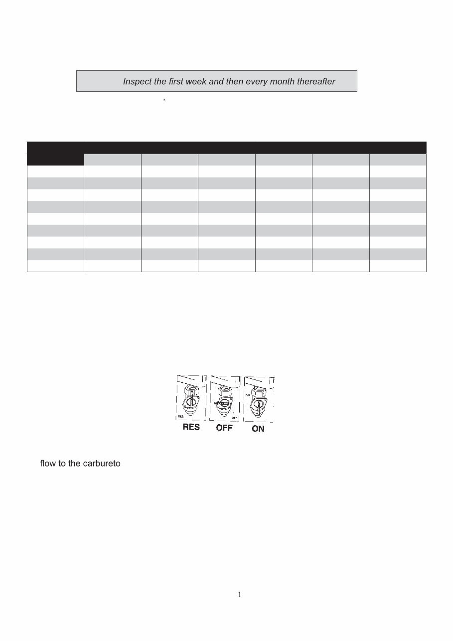
CHASSIS NUTS AND BOLTS Always pay attention to the unit s nuts and bolts. Some loosening after use is normal. Check to ensure that all nuts and bolts are tight. Torque Tightening Chart Bolt Conventional Marked Bolt 8.8 Marked Bolt Diameter N.m Kg.m Ib-ft N.m Kg.m Ib-ft 4 1 ~ 2 0.1 ~ 0.2 0.7 ~ 1.5 1.5 ~ 3 0.15 ~ 0.3 1.0 ~ 2.0 5 1 ~ 4 0.2 ~ 0.4 1.5 ~ 3.0 3 ~ 6 0.3 ~ 0.6 2.0 ~ 4.5 6 4 ~ 7 0.4 ~ 0.7 3.0 ~ 5.0 8 ~ 12 0.8 ~ 1.2 6.0 ~ 8.5 8 10 ~ 16 1.0 ~ 1.6 7.0 ~ 11.5 18 ~ 28 1.8 ~ 2.8 13.0 ~ 20.0 10 22 ~ 35 2.2 ~ 3.5 16.0 ~ 25.5 40 ~ 60 4.0 ~ 6.0 29.0 ~ 43.5 12 35 ~ 50 3.5 ~ 5.5 25.5 ~ 40 70 ~ 100 7.0 ~ 10.0 50.5 ~ 72.5 14 50 ~ 80 5.0 ~ 8.0 36.5 ~ 58 110 ~ 160 11.0 ~ 16.0 79.5 ~ 115.5 16 80 ~ 130 8.0 ~ 13.0 58 ~ 94 170 ~ 250 17.0 ~ 25. 123.0 ~ 181.0 18 130 ~ 190 13.0 ~19.0 94 ~ 137.5 200 ~ 280 20 ~ 28.0 144.5 ~ 202.5 FUEL SWITCH (PETCOCK) • Periodically clean the petcock externally with grease remover and water. • Check for any leaks or seeping fuel. • Replace the petcock if there are any leaks found. This vehicle has a manually operated fuel valve . There are three positions. “ON” position The normal operating position for the fuel valve lever is the “ON” position. In this position, fuel will r. “RES” position If the fuel level in the fuel tank becomes too low for the engine to operate with the fuel valve lever in the “ON” position, turn the lever to the “RES” position to use the reserve fuel supply, and refuel as soon as possible. “OFF” position The closing position for the fuel valve is the “OFF” position. When the vehicle is not in use, always make sure the petcock is in the “OFF” position. Note: .
2 before gear unit
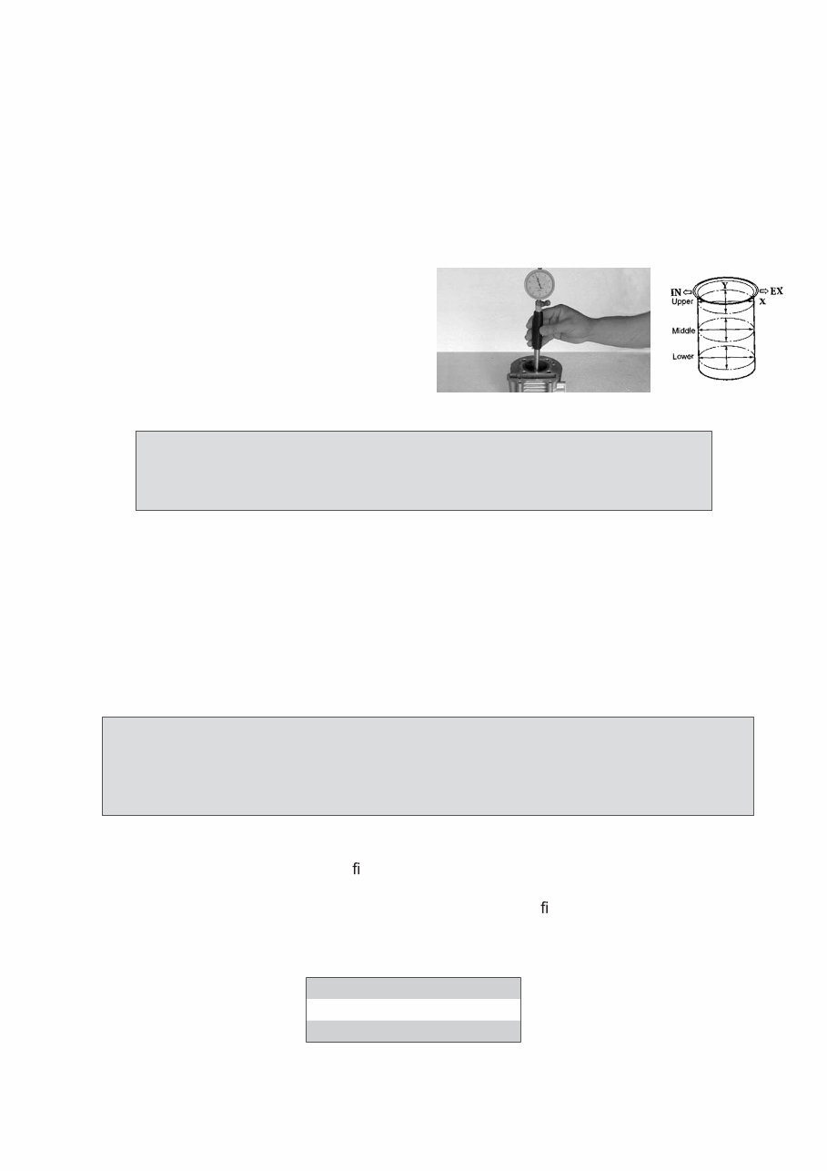
3 ENGINE ENGINE COMPONENTS INSPECTION AND SERVICING ENGINE COMPONENTS AND CRANK CONNECTING ROD MECHANISM INSPECTION AND SERVICING ENGINE COMPONENTS: CYLINDER CYLINDER REMOVAL The removal can be done on the vehicle body. • Remove cylinder head. • Remove cylinder. • Remove cylinder gasket, bolts • Clean cylinder gasket and remove any debris. CYLINDER INNER WALL WEAR INSPECTION Use a bore diameter dial gauge to measure the degree of wear. The measure point is divided into three sectional planes in the axial direction: upper, middle and lower; measure every plane each time on the mutually perpendicular directions (X, Y), the mea- sured least dimension is the cylinder bore; at the most upper position measured is the largest diameter, and the lowest position measured is the smallest diameter, their difference is the cylin- dricity of the cylinder. At the same cross section, measure the difference of diameter between two points mutually perpendicular; which is the circularity of the cylinder. In the situation without a dial gauge, a feeler gauge can be used to make relativity measurement. put a new piston into the cylinder, and use the feeler gauge to measure the gap between the piston skirt and the cylinder wall. T hen gure out the abrasion loss of the cylinder. If the circu- larity of the cylinder exceeds the limit, then a cylinder reboring machine should be used to rebore the cylinder, and enlarge its diameter by 0.5mm or 1.00mm, then t the piston and piston ring which size are also enlarged. If the wear is too severe and cannot be reworked, then a new cylin- der should be installed. Cylinder bore 57.4mm Cylindricity 0.05mm Circularity 0.05mm Caution! Do not damage the cylinder area. Make sure not to drop anything, including cylinder gasket material, into the crankcase. In order to make the measuring point perpendicular with the bore axis of the cyl- inder, and to ensure the precision of the measurement, the bar of the gauge can be slightly swung in the direction of the gauge bar, and take the smallest reading number as the result.
4
5
6
You're Reading a Preview
What's Included?
Lifetime Access
Fast Download Speeds
Online & Offline Access
Access PDF Contents & Bookmarks
Full Search Facility
Print one or all pages of your manual
$33.99
ACE ARROW 150CC Scooter Engine Service Repair Manual
Get your vehicle repair done today with our comprehensive service and repair manual. Whether you're a professional mechanic or a DIY enthusiast, this manual provides the best resources to save you money on repair costs and keep your vehicle in top condition.
Our manual includes step-by-step instructions, detailed exploded diagrams, and high-quality images to guide you through each repair job efficiently. It covers the entire vehicle from front to back, offering the same level of detail used by professional mechanics.
Access a wealth of information instantly
Easy-to-use manual
Print what you need, when you need it
The only service repair manual you'll ever need
Compatible with PC & MAC
Instant delivery means no shipping costs or waiting for a CD or paper manual. Upon secure payment completion, you'll receive the manual instantly. We accept Paypal and all major credit/debit cards.
Click on the button above to get started today. All rights reserved. Designated trademarks and brands are the property of their respective owners.
Reviews
Q&A
Recently Viewed
5,521,897Happy Clients
2,594,462eManuals
1,120,453Trusted Sellers
15Years in Business
Price:
Actual Price:
ACE ARROW 150CC Scooter Engine Service Repair Manual





 Lifetime Access




