

1995-1996 Volkswagen Automatic Transmission 01M Service & Repair Manual
What's Included?
Fast Download Speeds
Online & Offline Access
Access PDF Contents & Bookmarks
Full Search Facility
Print one or all pages of your manual

AUTO TRANS OVERHAUL - TYPE 01M
Article Text
1996 Volkswagen Passat
This file passed thru Volkswagen Technical Site - http://volkswagen.msk.ru
ARTICLE BEGINNING
AUTOMATIC TRANSMISSIONS
Volkswagen Type 01M - Auto Trans. Overhaul
Cabrio, Golf, Golf III, GTI Jetta, Jetta III, Passat
APPLICATION & LABOR TIMES
APPLICATION & LABOR TIMES
ÄÄÄÄÄÄÄÄÄÄÄÄÄÄÄÄÄÄÄÄÄÄÄÄÄÄÄÄÄÄÄÄÄÄÄÄÄÄÄÄÄÄÄÄÄÄÄÄÄÄÄÄÄÄÄÄÄÄÄÄ
Vehicle Labor Times Trans.
Application (1) R & I (2) Overhaul Model
1995-96
Cabrio ............... 4.4 ......... 6.3 .... 01M (CLK)
Golf, GTI & Jetta
4-Cylinder
Gas ................. 4.4 ......... 6.3 .... 01M (CLK)
Turbo Diesel ........ 4.4 ......... 6.3 .... 01M (CKZ)
V6 ................... 4.4 ......... 6.3 .... 01M (CLB)
Passat
4-Cylinder
Gas ................. 4.9 ......... 6.3 .... 01M (CLK)
Turbo Diesel ........ 4.9 ......... 6.3 .... 01M (CKZ)
V6 ................... 4.9 ......... 6.3 .... 01M (CLB)
(1) - Removal and installation of transmission from vehicle
chassis.
(2) - On bench overhaul for transmission and differential.
DOES NOT include removal and installation.
ÄÄÄÄÄÄÄÄÄÄÄÄÄÄÄÄÄÄÄÄÄÄÄÄÄÄÄÄÄÄÄÄÄÄÄÄÄÄÄÄÄÄÄÄÄÄÄÄÄÄÄÄÄÄÄÄÄÄÄÄ
IDENTIFICATION
Volkswagen Audi Group (VAG) transaxle type is cast into top
of transaxle case, next to ATF cooler. Transaxle code and build date
are located on top of transaxle case, next to starter.
DESCRIPTION & OPERATION
Transaxle includes a 4-speed automatic transmission, lock-up
torque converter, final drive and solenoid-operated valve body. See
Fig. 1. Under normal conditions, all shifts are controlled by a
Transaxle Control Module (TCM). See Fig. 2. Fourth gear is an
overdrive gear.
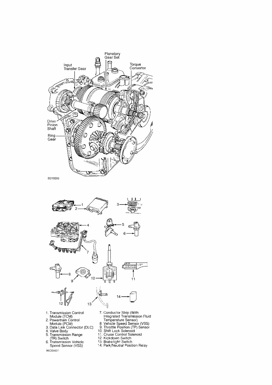
Fig. 1: Cross-Sectional View Of Transaxle Components
Courtesy of Volkswagen United States, Inc.
Fig. 2: Identifying TCM & Shift Lock Electrical Components
Courtesy of Volkswagen United States, Inc.
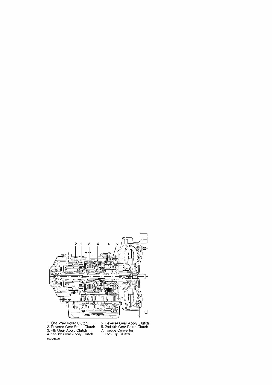
The transmission elements consist of a planetary gear set,
one-way roller clutch, 3 apply clutches, 2 brake clutches and a torque
converter lock-up clutch. See Figs. 1 and 3.
All 4 forward gears are hydraulically activated. When the
lock-up clutch is engaged, the forward gears become mechanically
driven by eliminating torque converter slip. The lock-up clutch is
engaged depending on engine load and vehicle speed.
Power from the transmission is connected to the drive pinion
through transfer gears. A ring gear and differential assembly are
connected to flanges which spin the drive axles.
The electronic control consists of a TCM (located under rear
seat), control solenoids, various sensors and switches. The control
solenoids direct oil pressure inside the valve body. Solenoid valves
No. 1-4 control the apply and brake clutches. Solenoid valves No. 5
and 7 control shift smoothness. Solenoid valve No. 6 is a frequency
valve and controls the main hydraulic pressure. The TCM controls the
main hydraulic pressure by varying the duty cycle.
The TCM monitors input and output signals. If electrical
problems occur, TCM will record faults in TCM memory and may go into
fail-safe mode (also known as emergency running mode). If TCM enters
fail-safe mode, the transaxle will operate manually in reverse, 1st or
3rd gear. In fail-safe mode, 3rd gear operates with gear selector in
2nd, 3rd or "D". If engine is started with TCM in fail-safe mode, TCM
activates 3rd gear hydraulically. The TCM memory can only be read
using Scan Tool (VAG 1551) and Adapter (VAG 1551/3).
The TCM also controls shift lock system. This system locks
the gear selector in Park or Neutral position unless the brake pedal
is pressed. The TCM uses a shift lock control relay to release a gear-
selector mounted solenoid. See Fig. 2.
Fig. 3: View Of Transaxle Clutch Elements
Courtesy of Volkswagen United States, Inc.
LUBRICATION & ADJUSTMENTS

NOTE: See appropriate AUTOMATIC TRANSMISSION SERVICING article in
TRANSMISSION SERVICING section.
TROUBLE SHOOTING
SYMPTOM DIAGNOSIS
Leak At Torque Converter
Check drive plate clearance, torque converter bushing, oil
seal or oil pump assembly. Repair as necessary.
Transaxle Fluid In Coolant
Faulty transaxle oil cooler. Replace transaxle oil cooler and
friction plates in transaxle. Clean transaxle.
Transaxle & Differential Oils Mixed
Replace "O" ring and drive pinion seal on inner bearing
support.
Gear Selector Hard To Move
Check gear selector between shifter and transaxle. Repair as
necessary. Check parking lock assembly inside transaxle. Repair as
necessary.
No Drive In 1st Gear
Check for faulty 1st-3rd apply clutch or reverse brake
clutch.
No Drive In "D", "2" Or "3"
Check for faulty 1st-3rd apply clutch or one-way clutch.
No 2nd Gear In "D", "2" Or "3"
Check for faulty 2nd-4th brake clutch.
No 3rd Gear In "D" Or "3"
Check for faulty reverse apply clutch.
No 4th Gear In "D"
Check for faulty 2nd-4th brake clutch.
No Reverse
Check for faulty reverse apply clutch or reverse brake
clutch.
No Drive In All Forward Gear Positions
Check for faulty 1st-3rd apply clutch, reverse brake clutch
or one-way clutch.
Missing Shifts Up Or Down
Check valve body for sticking valve(s) or faulty shift
solenoid(s).

Erratic Or Harsh Shifts
Short in wiring to shift solenoid(s) or faulty shift
solenoid(s). Check for proper throttle angle adjustment. See TECHNICAL
SERVICE BULLETINS.
Harsh Shift In One Gear Only
Determine elements involved. Air check elements. Check for
faulty shift solenoid or shift valve.
Stuck In Emergency Running Mode
Check for incorrect TCM installed, faulty wiring, bad
solenoid electrical strip (inside oil pan) or stuck valve.
Park Lock Will Not Engage
Check for misadjusted selector lever cable. Check for faulty
locking mechanism.
Bucking Or Poor Idling
Check throttle housing and air ducts for leaks. Check for
possible air entering oil pump pickup.
Excess Engine RPM Drop When Shifting Into 1st Gear
Faulty Powertrain Control Module (PCM).
Engine Starts In Gear Or No Start In Park/Neutral
Check for faulty Park/Neutral safety switch.
Shift Lock Not Holding Selector In Park/Neutral
Check for faulty shift lock solenoid, shift lock mechanism or
bad TCM.
MECHANICAL, HYDRAULIC & ELECTRICAL COMPONENTS
1) If gear selector is stuck in Park or Neutral position, go
to SHIFT LOCK SYSTEM under TROUBLE SHOOTING. If gear positions are
missing, shift quality is poor or no shifts are possible, ensure all
electrical connections are okay and fluid level is correct.
2) If problems are still present, disconnect electrical
connector at transaxle. Test drive vehicle. Check if transaxle will
operate manually in reverse and 1st gear. Move gear selector to 2nd,
3rd or "D" position. Transaxle should operate in 3rd gear (2nd, 3rd or
"D").
3) If transaxle operates as described, problem may be
electrical. See ELECTRONIC SELF-DIAGNOSTICS. If transaxle does not
operate as described, problem may be mechanical or hydraulic. See
ROAD TEST.
NOTE: If transaxle does not operate in manual 1st gear, check
1st-3rd apply clutch and reverse brake clutch for damage or
wear. If transaxle does not operate in manual reverse gear,
check reverse apply clutch and reverse brake clutch for
damage or wear.

ROAD TEST
WARNING: DO NOT exceed safe or legal speed limits during road test.
1) Road test vehicle with transaxle in "D" range. With
vehicle at a speed above kickdown speed, press throttle pedal down and
note kickdown shift speeds. Compare kickdown shift speeds to kickdown
shift speed specifications. See KICKDOWN SHIFT SPEED SPECIFICATIONS
table.
NOTE: In the following table, letter suffix following gear
application refers to Hydraulic ("H") or Mechanical ("M")
gear operation. Hydraulic or manual gear operation depends
on operating mode of torque converter lock-up clutch.
KICKDOWN SHIFT SPEED SPECIFICATIONS
ÄÄÄÄÄÄÄÄÄÄÄÄÄÄÄÄÄÄÄÄÄÄÄÄÄÄÄÄÄÄÄÄÄÄÄÄÄÄÄÄÄÄÄÄÄÄÄÄÄÄÄÄÄÄÄÄÄÄÄÄ
Application Kickdown (MPH)
4-Cylinder (CLK)
1H-1M ............................................ 30-34
1M-2H ............................................ 30-34
2H-2M ............................................ 61-65
2M-3H ............................................ 61-65
3H-3M ............................................ 85-89
3M-4H ............................................ 85-89
4H-4M ............................................ 85-89
4M-4H ............................................ 86-83
4H-3M ............................................ 86-83
3M-3H ............................................ 61-57
3H-2M ............................................ 61-57
2M-2H ............................................ 61-57
2H-1M ............................................ 26-22
1M-1H ............................................ 26-22
Turbo Diesel (CKZ) .................................. (1)
V6 (CLB)
1H-1M ............................................ 37-41
1M-2H ............................................ 37-41
2H-2M ............................................ 76-80
2M-3H ............................................ 76-80
3H-3M .......................................... 111-115
3M-4H .......................................... 111-115
4H-4M .......................................... 111-115
4M-4H .......................................... 112-108
4H-3M .......................................... 112-108
3M-3H ............................................ 75-71
3H-2M ............................................ 75-71
2M-2H ............................................ 75-71
2H-1M ............................................ 32-28
1M-1H ............................................ 32-28
(1) - Information not available from manufacturer.
ÄÄÄÄÄÄÄÄÄÄÄÄÄÄÄÄÄÄÄÄÄÄÄÄÄÄÄÄÄÄÄÄÄÄÄÄÄÄÄÄÄÄÄÄÄÄÄÄÄÄÄÄÄÄÄÄÄÄÄÄ

2) Connect scan tool and appropriate adapter to diagnostic
connector. Select function 08 "READ MEASURING VALUE BLOCK". Test
solenoid valves and upshift speeds following scan tool manufacturers
instructions.
3) If transaxle does not shift within specified MPH range,
and scan tool values are within specification, determine affected
elements. See APPLY & BRAKE CLUTCH APPLICATION.
4) If all apply and brake clutch elements are affected, check
oil pump, oil filter, cooler lines, solenoid valve No. 6, and
condition of torque converter and/or engine. Repair as necessary.
5) If one or more apply and brake clutch elements are
affected, remove valve body. Locate appropriate fluid circuit in
transaxle case and valve body. Check for leaks and/or blockage. Repair
as necessary.
6) If hydraulic circuits are okay, or problems with apply and
brake clutch elements are mechanical, repair transaxle.
NOTE: If transaxle does not operate in manual 1st gear, check
1st-3rd apply clutch and reverse brake clutch for damage or
wear. If transaxle does not operate in manual reverse gear,
check reverse apply clutch and reverse brake clutch for
damage or wear.
APPLY & BRAKE CLUTCH APPLICATION
APPLY & BRAKE CLUTCH APPLICATION (1)
ÄÄÄÄÄÄÄÄÄÄÄÄÄÄÄÄÄÄÄÄÄÄÄÄÄÄÄÄÄÄÄÄÄÄÄÄÄÄÄÄÄÄÄÄÄÄÄÄÄÄÄÄÄÄÄÄÄÄÄÄ
Gear Application Elements In Use
1st Gear .......... 1st-3rd Apply & One-Way Clutch Holding
2nd Gear ................... 1st-3rd Apply & 2nd-4th Brake
3rd Gear .................... 1st-3rd & 4th Apply Clutches
4th Gear ....................... 4th Apply & 2nd-4th Brake
Reverse .................... Reverse Apply & Reverse Brake
Park & Neutral ................ All Apply & Brake Clutches
Released Or Ineffective
(1) - All forward gear elements shown are in "hydraulic-state".
Forward gear elements switch to a "mechanical-state"
with the addition of torque converter lock-up clutch
apply.
ÄÄÄÄÄÄÄÄÄÄÄÄÄÄÄÄÄÄÄÄÄÄÄÄÄÄÄÄÄÄÄÄÄÄÄÄÄÄÄÄÄÄÄÄÄÄÄÄÄÄÄÄÄÄÄÄÄÄÄÄ
SHIFT LOCK SYSTEM
Operation
All models are equipped with an electronic shift lock system.
TCM controls shift lock system. See Fig. 2. This system locks gear
selector in Park or Neutral position unless brake pedal is pressed.
TCM uses shift lock control relay to release a solenoid mounted on
gear selector assembly.

NOTE: Shift lock relay will not lock gear selector when vehicle
speed is greater than 3 MPH.
A mechanical control cable prevents ignition key from being
removed unless gear selector is in Park position. With ignition key
removed, gear selector locks in Park position.
NOTE: If battery is disconnected or discharged, gear selector can
be moved out of Park position by turning ignition key to
START position.
Functional Check
1) With ignition key removed, ensure gear selector cannot be
moved from "P" position. Insert key in ignition switch.
2) Turn ignition on. Ensure gear selector can only be moved
with brake pedal pressed. Move gear selector to "N" position.
3) Without pressing brake pedal, ensure gear selector cannot
move out of "N" position. Press brake pedal down. Ensure it is now
possible to move gear selector.
4) If shift lock system does not operate as described, adjust
gear selector, solenoid and control cable. If shift lock system does
not operate after adjustments are made, check shift lock electrical
system with Scan Tool (VAG 1551).
5) See testing information under ELECTRONIC SELF-DIAGNOSTICS.
See Figs. 10-13. If any problems are found, service harness or
components. If no problems are found, TCM may be defective. If shift
lock system still does not operate correctly, check for worn or
damaged parts and replace as necessary. See Figs. 2 and 4.
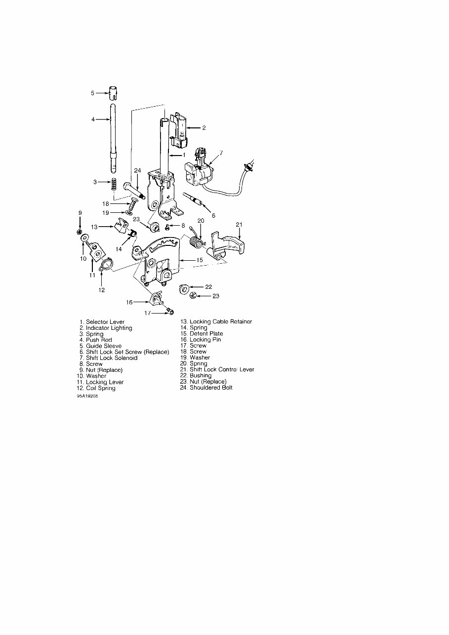
Fig. 4: Exploded View Of Shift Lock & Gear Selector Assembly
Courtesy of Volkswagen United States, Inc.
NOTE: Perform the following adjustments in order given.
Control Cable Adjustment
Loosen lock screw at gear selector lever on transaxle. Move
gear selector in center console to Park position. Ensure front wheels
are locked. Tighten cable housing to gear selector lever lock screw.
Shift Lock Solenoid Adjustment
Place gear selector in "N" or "P" position. Loosen shift lock
solenoid mounting screws. Insert a .019" (.30 mm) feeler gauge between
shift lock solenoid push rod and shift lever. See Fig. 5. If
necessary, move shift lock solenoid and tighten screws.
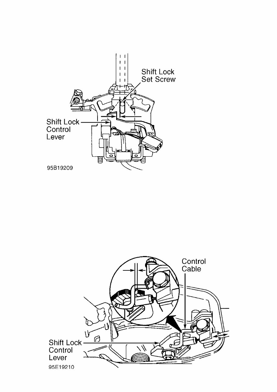
Fig. 5: Adjusting Shift Lock Solenoid
Courtesy of Volkswagen United States, Inc.
Shift Lock Cable Adjustment
1) Move gear selector to "1" position. Remove steering column
covers. Turn ignition key to START position and release. Check
clearance between shift lock cable lever and ignition switch locking
pin.
2) Clearance should be .028" (.70 mm). If clearance is not
correct, loosen lock nut on shift lock cable sheath. Position shift
lock cable lever to obtain correct clearance. Tighten lock nut. See
Fig. 6. Tighten gear selector housing screws and install steering
column covers.
Fig. 6: Adjusting Shift Lock Cable
You're Reading a Preview
What's Included?
Fast Download Speeds
Online & Offline Access
Access PDF Contents & Bookmarks
Full Search Facility
Print one or all pages of your manual
$37.99
$49.99
Viewed 27 Times Today


Secure transaction
What's Included?
Fast Download Speeds
Online & Offline Access
Access PDF Contents & Bookmarks
Full Search Facility
Print one or all pages of your manual
$37.99
$49.99
This is a comprehensive service manual for the 1995-96 Automatic Transmission Type 01M. It covers automatic transmission servicing and provides detailed trouble shooting symptom diagnosis for the following vehicles:
- Cabrio 4.4, 6.3 01M (CLK)
- Golf, GTI & Jetta 4-Cylinder Gas 4.4, 6.3 01M (CLK)
- Golf, GTI & Jetta Turbo Diesel 4.4, 6.3 01M (CKZ)
- Golf, GTI & Jetta V6 4.4, 6.3 01M (CLB)
- Passat 4-Cylinder Gas 4.9, 6.3 01M (CLK)
- Passat Turbo Diesel 4.9, 6.3 01M (CKZ)
- Passat V6 4.9, 6.3 01M (CLB)
The manual includes detailed instructions for the removal and installation of the transmission from the vehicle chassis, as well as on-bench overhaul for the transmission and differential. Please note that it does not include the removal and installation process.


