

Vintage Old School Go-Kart Plans
What's Included?
Fast Download Speeds
Online & Offline Access
Access PDF Contents & Bookmarks
Full Search Facility
Print one or all pages of your manual
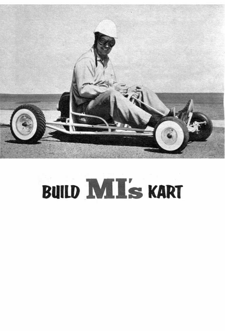
By S. Calhoun Smith
T
HE "go kart" has taken the U. S. by
storm. A happy wedding of lawn
mower engine and steel tubing on four
little wheels, it has become a craze
among kids and adults with a yen for
racing or just plain driving fun.
Kart racing originated in California
and has spread eastward since 1956.
Now the GKCA (Go Kart Club of
America) is firmly established and has
set up sensible rules governing design
and power for stable, safe "karting."
Even the lowest powered Class A, 2.5
102
hp karts are capable of 30 to 35 mph
with an adult aboard and more when
driven by a lightweight 10-year-old.
Races are run on paved parking lots and
small dirt ovals and regular sports car
type raceways have been built with
tracks four-tenths of a mile in length
and 20 feet wide. Such tracks incorpor-
ate eleven turns, both banked and flat.
The MI Kart was designed and built
by Bob Peru of Red Bank, N. J. and
can be considered a basic Class A kart.
It complies in all respects with GKCA
Mechanix Illustrated
A 2-1/2,-hp lawn mower engine drives this kart at
more than 30 mph. It's Class A fun for anyone.
specifications. Cost runs from $100 to
$110 complete with an A-400 Clinton
engine. Peru did the welding himself
but anyone not equipped to do it would
have to spend $20 to $30 extra. The
building time was about 25 hours and
the tools required were a square, hack
saw, tin snips, files, hammer, large vise
and an electric hand drill or drill press.
To help hold cost down, the frame is
made of thin-wall conduit, but more ex-
pensive chrome-moly tubing could be
substituted throughout. Some parts,
the seat and steering hoops, steering
COMPLETED FRAME with axles installed;
a thin-wall conduit is used to reduce cost
BELLY PAN and seat back are sheet steel;
they're spot-welded to the conduit frame.
January, 1960 103
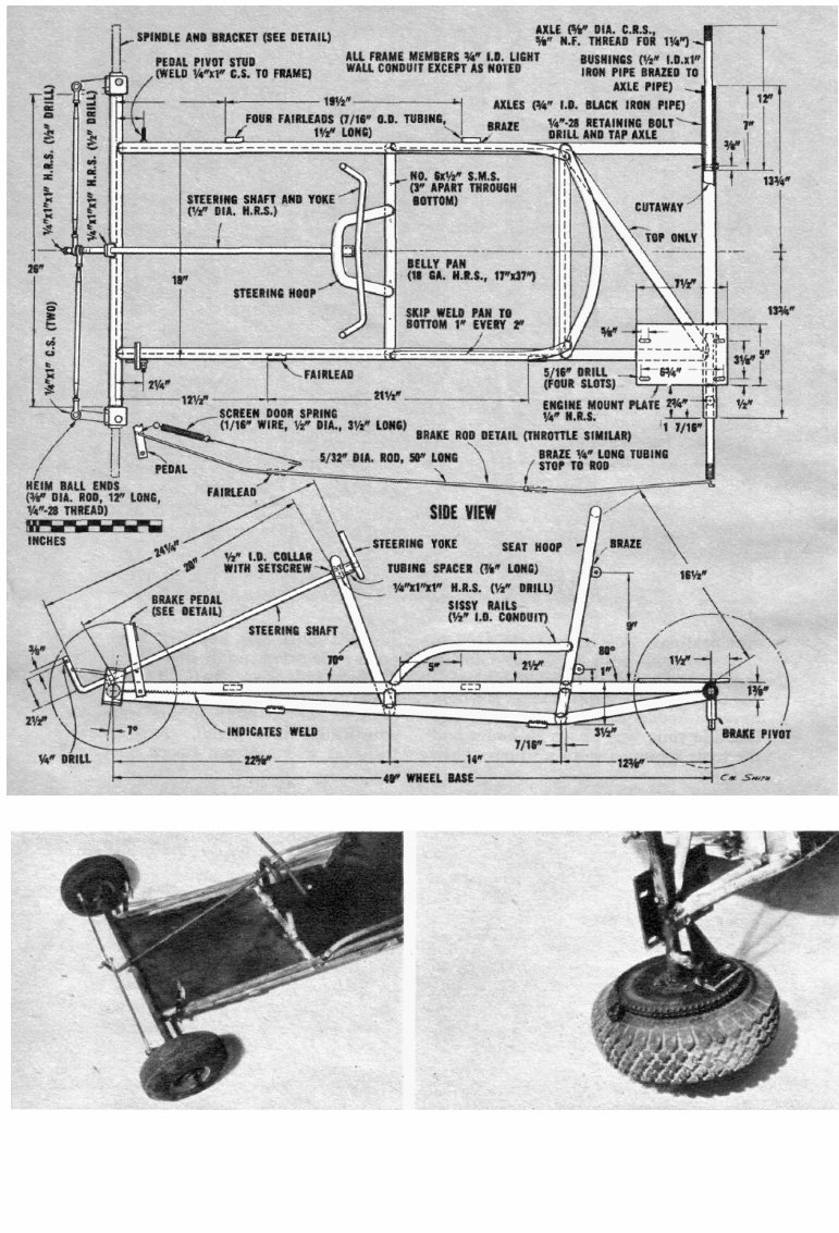
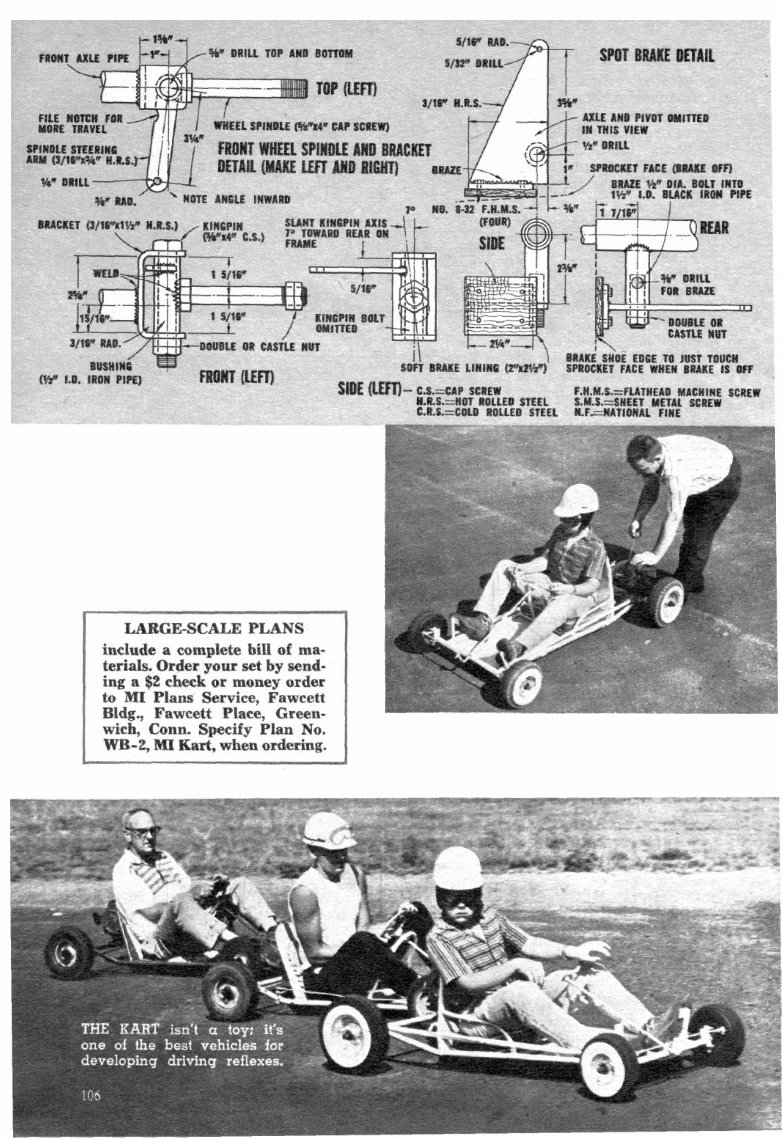
FRONT END view shows brake and throttle
pedals and the simple steering mechanism.
SPOT BRAKE pivots flush against inside
face of sprocket. Note engine mount plate.
104 Mecha.nlx Illustrated
yoke, front wheel spindle
brackets and engine
mount plate, can be pur-
chased ready-formed from
various kart manufac-
turers. Their use will
speed building consider-
ably-
Begin construction by
drawing a side frame out-
line on a piece of scrap
lumber. Cut and flare the
tubing required and heat
the lower piece to make
the bend. Fit the pieces
over the outline and clamp
them. Then tack weld all
joints and remove the
framing from the board.
Using the first side as a
pattern, clamp the parts of
the second to it and tack
weld them together. This
will insure uniformity.
Next fabricate the front
and rear axles. Bend
the front wheel spindle
brackets to shape and drill
them for the kingpin bolts.
Then weld them to the
front axle tube. Align
them carefully, square on
the tube ends and parallel
to each other. The rear
axle tube ends are bushed
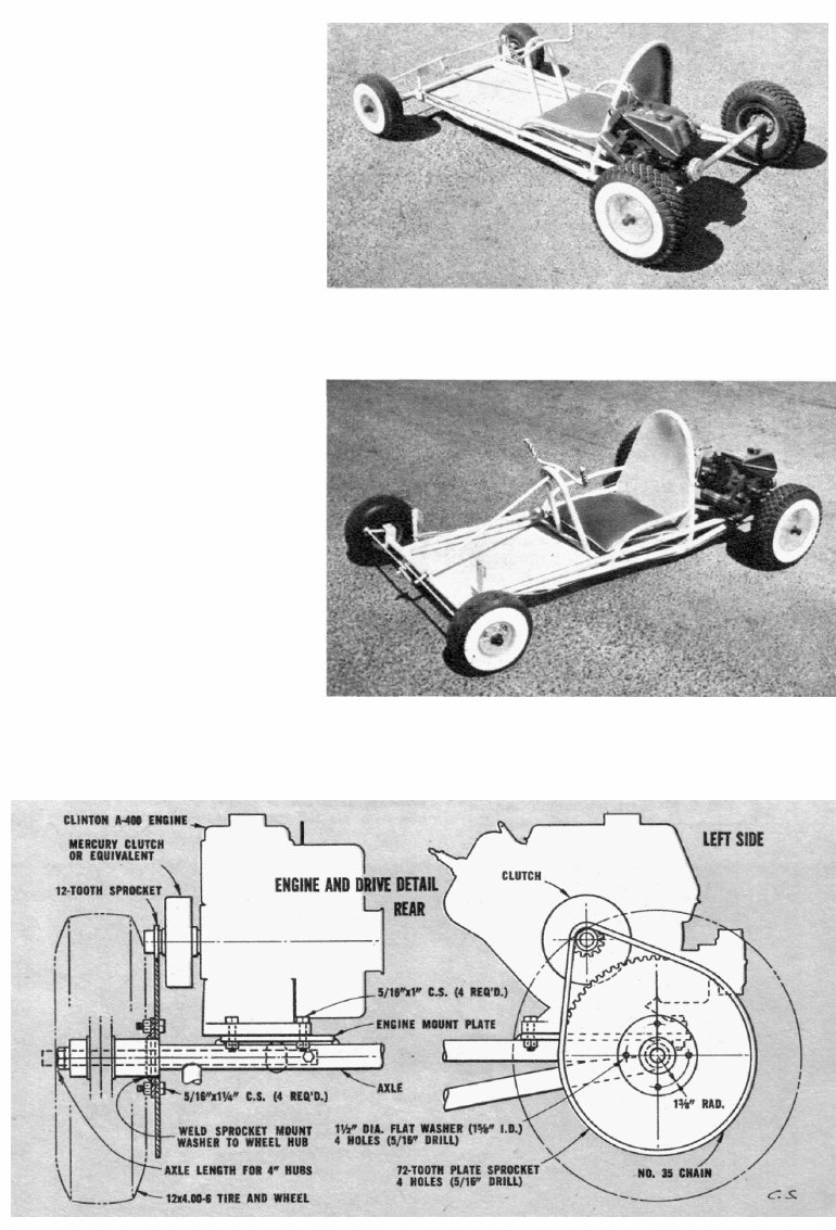
CLINTON 2-1/2-hp engine drives MI kart at more than 30
mph with adult load; note throttle crank on seat hoop.
SPANKING NEW kart is ready to go. You can upholster
seat but boat cushion from marine supplier does nicely.
with a length of pipe to reduce the
inside diameter for the 5/8-inch
round stock axles. The axles are
held in the tube with a quarter-
inch bolt near each inner end.
They can be tapped for short bolts
or holes [Continued on page 150]
RECOIL STARTER is pulled as youthful driver
sits with his left foot depressing brake pedal.

Build MI's Kart
[Continued from page 106]
can be drilled all the way through for bolts
and nuts.
The side frames, axles and crosspieces
can now be assembled. Cut and flare the
pieces and tack weld them, using a try
square to make sure they're aligned. Add
the axles to the frame ends, squaring up
the assembly as it progresses. Note that
the front axle is rotated slightly in the side
frame ends so that the kingpin axis has a
7° rearward slant. The frame-axle assem-
bly can now be completely welded at all
joints. As the last step, add the diagonal
crosspiece at the rear.
The front wheel spindle units are made
up next. Cut the kingpin bushing tubes to
fit snug inside the brackets. Then weld the
wheel spindle bolts to the sides of the bush-
ings. Follow this by welding the spindle
steering arm pieces to the bushings. Note
that right- and left-hand units are required
since the steering arm pieces slant inward.
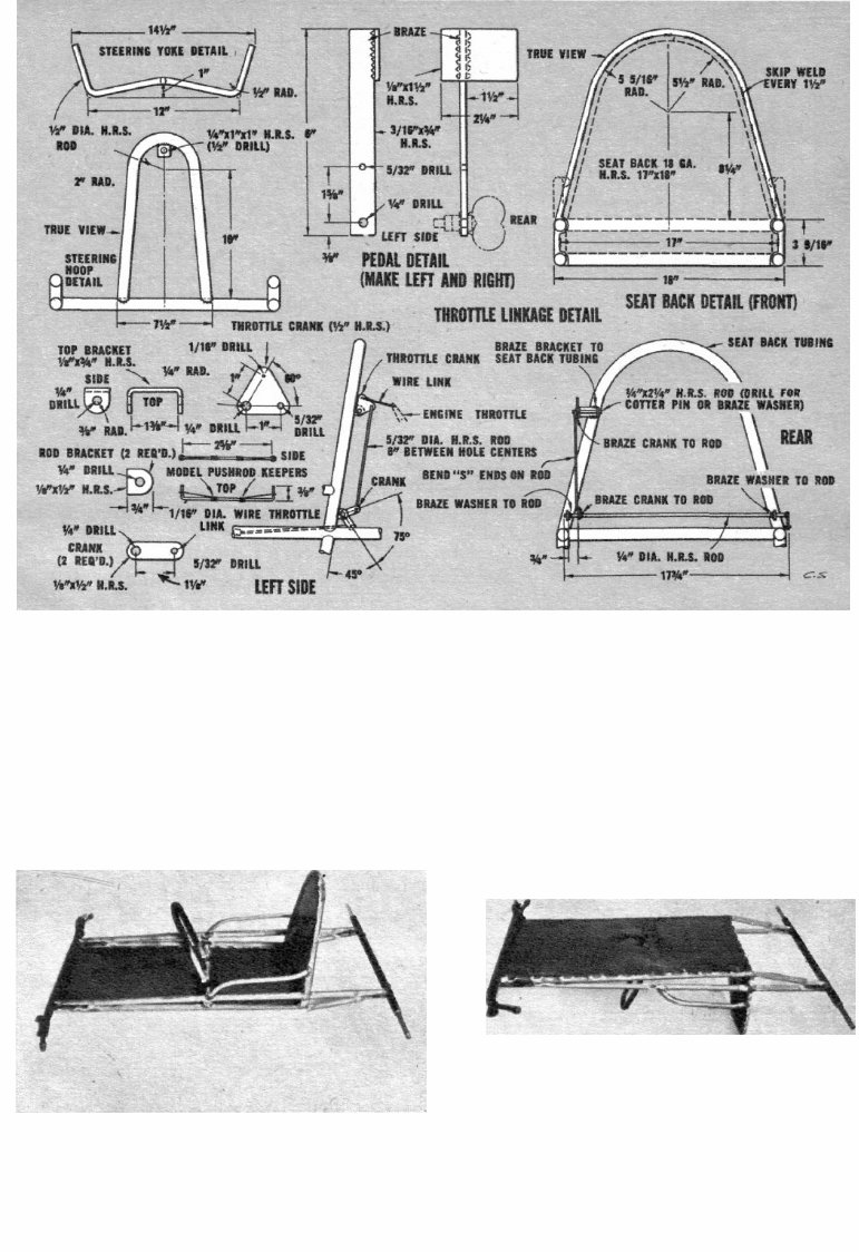
The steering and seat hoops are now
formed and cut to fit onto the frame. To
make the curves, apply heat and bend a
little at a time so that the tubing will not
deform. Tack weld the hoops in position
after clamping them at the proper angles;
then complete the welds. Next cut the
belly pan and seat back to shape, checking
the pieces against the frame for correct di-
mensions. Tack weld the belly pan in place
on the bottom of the frame and then skip
weld the pan edges to the frame. Welds
should be about one inch long and two
inches apart. Where the pan touches the
crosspiece at the steering hoop rosette,
welds can be used or the sheet and tubing
can be drilled for self-tapping sheet metal
screws. To prevent the sheet steel from
buckling during welding, use a chill block
clamped about a quarter-inch from the
edge along the area to be welded. The chill
block can be a piece of 1/2xlx24-inch
steel bar stock. The seat back is skip
welded to the front of the seat hoop in the
same manner as the belly pan. Make half-
round cuts to clear the side frame tubes.
Sissy rails can now be bent to shape, fitted
to the sides and seat hoop and welded in
place.
The steering assembly is made next. Cut
and drill the steering shaft support
brackets of 1/4xl-in strip steel. Bend the
steering shaft front end and drill it for the
tie-rod bolt. Then bend the yoke to shape.
Put brackets and collars on the steering
shaft and weld the yoke to the shaft end.
Next slide the shaft through the top
bracket to spread out the collars and weld
the bracket to the underside of the hoop
curve. Hold the lower end of the shaft at
the proper angle to align the top bracket
while welding. Finish by sliding the shaft
into position and welding the front bracket
to the top of the front axle.
The tie-rod ends are threaded for about
one inch to match the Heim ball end fit-
tings. Clevis end or Ford brake rod ends
could be substituted if the ball ends are
not readily available. Adjust the rod ends
at the center to align the wheel spindles
at zero degrees. Toe-in or toe-out can be
adjusted later when the kart's running
qualities have been checked. While work-
ing on the front end, weld the pedal pivot
bolts to the side frames.
Drive and engine mount parts are next
on the list. The wheel hub is first fitted
with a large washer for bolting on the
large sprocket. This permits removal of the
sprocket if different sizes are to be fitted.
(If you do not wish to bother with removal,
the sprocket can be welded flush to the
wheel hub inside face.) The large washer
and sprocket are drilled for mounting
bolts. Disassemble the wheel to make
welding on the hub easier. The large
washer is welded to the hub 3/16-in from
the inside face so that the hub forms a
shoulder for centering the sprocket. Weld
the washer from behind, aligning it care-
fully so that it and the sprocket will track
without any wobble. After assembly,
mount the drive wheel and sprocket on the
axle. Next bolt the engine to the mount
plate, install the clutch (if used) and the
chain. Now carefully align the chain and
sprockets, moving the engine and mount
on the frame. When set, mark the position
and clamp the mount plate to the frame.
Then remove the engine and wheel and
weld the mount plate to the frame. The
engine mounting bolts should be in the
center of the slots so that the engine can
be shifted to correct for wear on the chain
150 January, 1960

Build MI's Kart
and sprocket.
The spot brake is made and installed
next. Detail drawings are self-explanatory,
but follow this procedure for mounting on
the axle: mount drive wheel on axle;
mount brake on pivot bolt and tube; clamp
brake firmly to sprocket in "brake" posi-
tion (this will position pivot tube on bot-
tom of axle tube); then clamp and weld
pivot tube to axle.
The throttle linkage is made next. Cut
out and drill all parts shown on the detail
drawing. Then put the engine in place on
the mount so that the upper linkage parts
can be aligned with the engine throttle.
The brackets, rods and cranks can be as-
sembled by brazing. Complete the throttle
and brake linkage by making the pedals
and push rods. Note that there are right-
and left-hand pedals. Remember to slide
the fairleads and stop tubes onto the push
rods before bending the S ends. Rods can
be fitted with clevis ends if desired so that
adjustments can be made. Fit one end of
the rod to the brake at the rear and put the
pedal on the other end. Next put the pedal
on the pivot bolt at the front, clamp the
fairleads to the side frames and braze them
in place. Braze the stop to the rod ahead of
the fairlead with the brake off and clear of
the sprocket. The throttle push rod and
pedal are assembled in a similar manner.
Last, make and install return springs on
both pedals.
This completes the metal work on the
kart. All welds should be wire brushed.
Welding splatters and braze flux should be
chipped off all metal surfaces and the
metal cleaned before painting. It's a good
idea to clean up the welds during fabrica-
tion for easy access to the tight corners.
The Clinton engine, of course, is not the
only one which can be used; West Bend,
Briggs & Stratton, Continental, Power
Products and McCulloch engines fill the
bill with slight mount modifications. The
builder who wishes to customize his kart
will find such items as mufflers, drum
brakes, chromed tanks, steering wheels
and racing slicks available from the many
kart manufacturers. You can add what-
ever your pocketbook will allow—but sim-
ple or dressed up, the MI kart is a kartload
of fun. •
You're Reading a Preview
What's Included?
Fast Download Speeds
Online & Offline Access
Access PDF Contents & Bookmarks
Full Search Facility
Print one or all pages of your manual
$27.99
Viewed 67 Times Today


Secure transaction
What's Included?
Fast Download Speeds
Online & Offline Access
Access PDF Contents & Bookmarks
Full Search Facility
Print one or all pages of your manual
$27.99
Explore vintage plans reprints from the 1960s to construct a classic go-kart, perfect for enthusiasts and professional mechanics alike. These meticulously restored and enlarged plans offer superior clarity and intricate details, allowing for easy viewing and printing as required. The 7-page manual is available in PDF format, compatible with Adobe Reader or Acrobat on all computer systems. While the original engines recommended in these plans are older models like Clintons and McCullochs, they can be effortlessly substituted with newer parts and engines for modern customization.


