

InSinkerator Food service Commercial Disposer Service Manual
What's Included?
Fast Download Speeds
Online & Offline Access
Access PDF Contents & Bookmarks
Full Search Facility
Print one or all pages of your manual
SERVICE MANUAL
Commercial Disposers
SS-50
SS-75
SS-100
SS-125
SS-150
SS-200
SS-300
SS-500
SS-750
SS-1000
Part No. F376-09L-76-02 © 2009

Service Manual i
Commercial Disposers
GENERAL INFORMATION .................................................................................................................................... 3
SAFETY SIGNALS ....................................................................................................................................................... 3
COMMERCIAL DISPOSERS ....................................................................................................................................... 3
PRIOR TO SERVICE CALL ......................................................................................................................................... 3
AFTER COMPLETING SERVICE ................................................................................................................................ 3
COMMERCIAL DISPOSER
PARTS LIMITED WARRANTY ..................................................................................................................................... 4
SERIAL NUMBER DATE CODE .................................................................................................................................. 4
SPECIFICATIONS..................................................................................................................................................... 5
COLD WATER FLOW & DRAIN LINE DIAMETER ...................................................................................................... 5
DIMENSIONS .............................................................................................................................................................. 5
ELECTRICAL REQUIREMENTS ................................................................................................................................. 7
RECOMMENDED INSTALLATION .............................................................................................................................. 8
REMOVING DISPOSER .............................................................................................................................................. 9
INSTALLING DISPOSER ............................................................................................................................................. 9
PREPARATION FOR REPAIR .............................................................................................................................. 9
COMMON REPAIR AREAS ....................................................................................................................................... 10
TERMINAL BOX & TRIM BAND .................................................................................................................................11
GRINDING CHAMBER.......................................................................................................................................... 12
REPLACING WATER INLET ...................................................................................................................................... 12
REPLACING SHREDDER GASKET ......................................................................................................................... 12
REPLACING STATIONARY SHREDDER .................................................................................................................. 13
REPLACING ROTATING SHREDDER ...................................................................................................................... 14
REPAIRING UPPER END BELL ASSEMBLY ........................................................................................................... 15
UPPER END BELL (UEB) .................................................................................................................................... 15
ELECTRICAL REPAIRS ....................................................................................................................................... 18
OVERLOAD PROTECTOR ........................................................................................................................................ 18
CAPACITOR .............................................................................................................................................................. 19
BOTTOM COVER AND FAN ...................................................................................................................................... 20
LOWER END FRAME (LEF) ...................................................................................................................................... 21
REPLACING START SWITCH
(1 PHASE MODELS) ................................................................................................................................................. 21
STATOR ..................................................................................................................................................................... 22
MOTOR LEADS CONNECTIONS.............................................................................................................................. 23
WIRING DIAGRAMS.............................................................................................................................................. 24
TROUBLESHOOTING........................................................................................................................................... 27
EXPLODED VIEWS & PARTS LISTS .............................................................................................................. 32
TABLE OF CONTENTS

Service Manual ii
Commercial Disposers
NOTES
_________________________________________________________________________________________________________
_________________________________________________________________________________________________________
_________________________________________________________________________________________________________
_________________________________________________________________________________________________________
_________________________________________________________________________________________________________
_________________________________________________________________________________________________________
_________________________________________________________________________________________________________
_________________________________________________________________________________________________________
_________________________________________________________________________________________________________
_________________________________________________________________________________________________________
_________________________________________________________________________________________________________
_________________________________________________________________________________________________________
_________________________________________________________________________________________________________
_________________________________________________________________________________________________________
_________________________________________________________________________________________________________
_________________________________________________________________________________________________________
_________________________________________________________________________________________________________
_________________________________________________________________________________________________________
_________________________________________________________________________________________________________
_________________________________________________________________________________________________________
_________________________________________________________________________________________________________
_________________________________________________________________________________________________________
_________________________________________________________________________________________________________
_________________________________________________________________________________________________________
_________________________________________________________________________________________________________
_________________________________________________________________________________________________________
_________________________________________________________________________________________________________
_________________________________________________________________________________________________________
_________________________________________________________________________________________________________
_________________________________________________________________________________________________________
_________________________________________________________________________________________________________
_________________________________________________________________________________________________________
_________________________________________________________________________________________________________
_________________________________________________________________________________________________________
_________________________________________________________________________________________________________
_________________________________________________________________________________________________________
_________________________________________________________________________________________________________
_________________________________________________________________________________________________________
_________________________________________________________________________________________________________
Service Manual 1
Commercial Disposers
Safety Signals
This symbol indicates potential personal injury hazards.
Obey all safety messages accompanying this symbol to
avoid possible injury or death.
DANGER indicates an imminently hazardous
situation which, if not avoided, will result in
death or serious injury.
WARNING indicates a potentially hazardous
situation which, if not avoided, could result in
death or serious injury.
CAUTION indicates a potentially hazardous
situation which, if not avoided, may result in
minor or moderate injury.
Commercial Disposers
InSinkErator
®
manufactures commercial food waste disposers
with motors ranging from 1/2 horsepower through 10 horsepower.
The basic assembly of all SS Series commercial disposers is iden-
tical. However, electrical connections vary depending upon the
disposer specifications, power supply, and electrical controls.
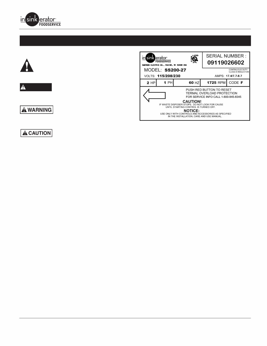
Specification Decal
The specification decal (Figure 1) located on the motor trim cover
indicates
• complete model number (example - SS150-24)
• serial number (includes manufactured date)
• amperage
• voltage
• phase
• horsepower.
NOTE: The correct part sheet (as designated by the complete
model number) must be referenced to order replacement parts.
DANGER
Figure 1. Specification Decal
Prior to Service Call
• Obtain the model number, serial number, voltage and phase
from the customer to prepare for the service call.
• Date of installation.
• Obtain the service history of the disposer.
• Make sure the customer has tried resetting the overload pro-
tector and has checked for foreign objects jammed in the
grind chamber (see “Troubleshooting” on page 25).
• Before troubleshooting for mechanical problems, determine if
the problem is electrical:
• To determine if the problem is in the switch or the dispos-
er, bypass all electrical starting and/or electrical controls
and run the disposer direct.
• Make sure the disposer electrical specifications match
the electric power supply.
• Make sure the motor lead connections are correct for the
corresponding power supply and starting controls.
• Determine if there are electrical problems with other
kitchen appliances. This may indicate a problem in the
building’s electrical circuitry.
After Completing Service
Test the disposer for proper operation and ensure that the fittings
are secure and do not leak.
GENERAL INFORMATION
Service Manual 2
Commercial Disposers
Commercial Disposer
Limited Warranty
InSinkErator
®
commercial disposers are warranted against defects
in material and workmanship for one year from the date of installa-
tion. The warranty includes parts and labor, provided the service is
performed by an InSinkErator Factory Authorized Service Center.
This warranty does not apply if failure is due to :
• Faulty or improper electrical installation
• Faulty or improper plumbing installation
• Product abuse or misuse
• Accidental damage
• Grinding elements jammed by foreign objects
• Clogged drain lines
• Unit improperly sized or improper water flow (as specified in
the Disposer Sizing Chart and Recommended Cold Water
Flow Chart in this manual..
Commercial Disposer
Parts Limited Warranty
Replacement parts installed on OUT OF WARRANTY dispos-
ers are covered (parts and labor) for 90 days from the date
the parts are installed, provided the service is performed by an
InSinkErator Factory Authorized Service Center. To receive credit,
the Service Agency must provide a copy of the service invoice
given to the customer as a receipt for the replacement part.
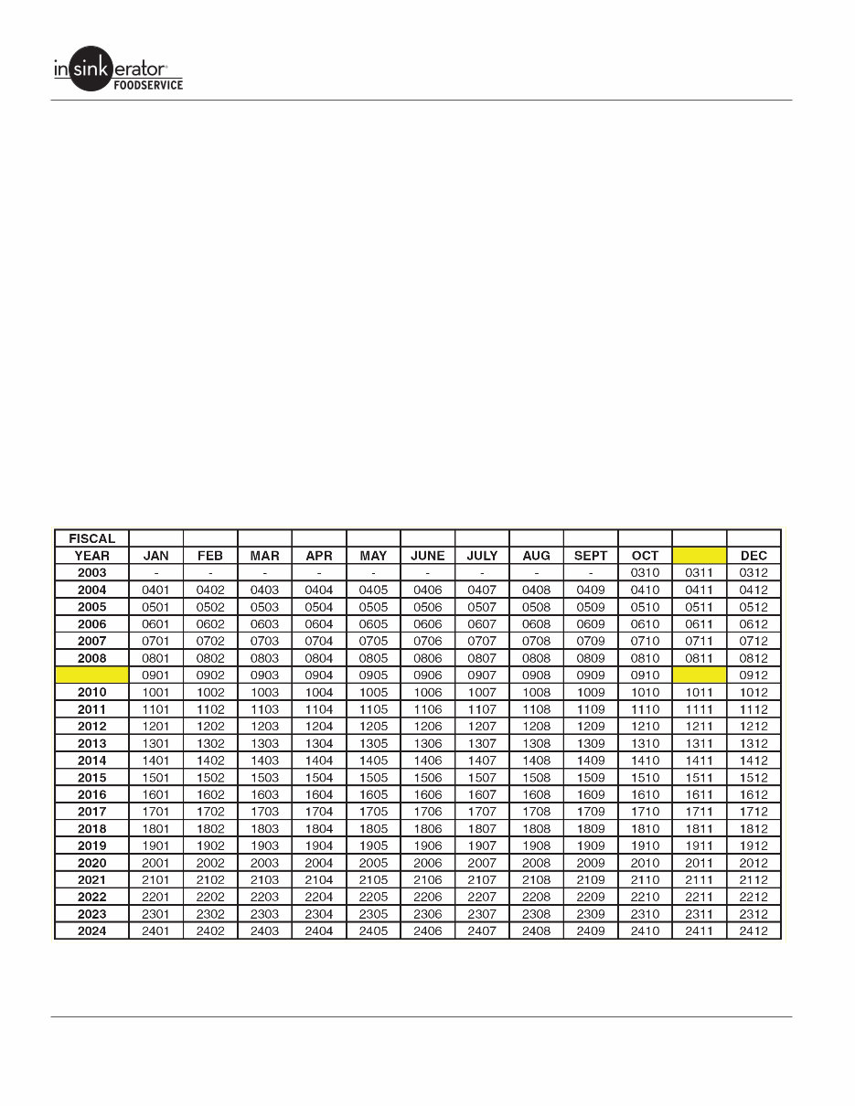
Serial Number Date Code
Example: 09110000000 09 = Year of Manufacture
11 = Month of Manufacture
2009 09
Service Manual 3
Commercial Disposers
Cold Water Flow & Drain Line Diameter
Disposer
Water Flow
GPM (LPM)
Drain Line Diameter
Inches (MM)
SS-50 3 (11) 1-1/2" (38)
SS-75 3 (11) 1-1/2” (38)
SS-100 5 (19) 1-1/2”(38)
SS-125 5 (19) 1-1/2” (38)
SS-150 7 (26) 2" NPT (51)
SS-200 7 (26) 2” NPT (51)
SS-300 8 (30) 3" NPT (51)
SS-500 8 (30) 3” NPT (51)
SS-750 10 (38) 3” NPT (51)
SS-1000 10 (38) 3” NPT (51)
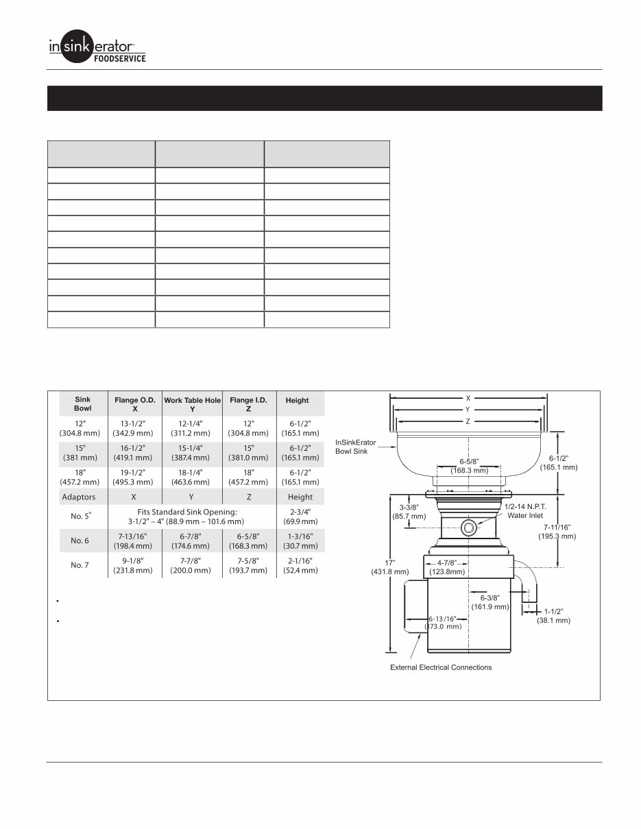
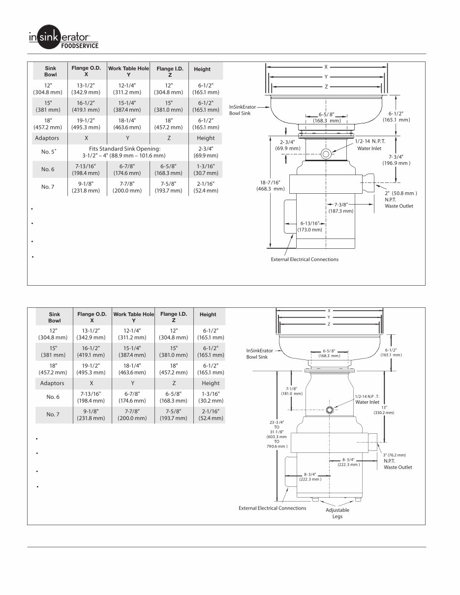
Dimensions
IMPORTANT: Use the following dimension charts for adaptor height in place of InSinkErator sink bowl height when mounting directly
to a sink. Dimensions - Models SS-50, SS-75, SS-100 & SS-125.
NOTE:
Adaptors are available upon request for all competitor
sink bowls or cones.
Please have sink/bowl cone type with the necessary
dimensions when ordering adaptors.
* It is recommended to add legs (Part No.11757C) with No. 5 Mounting Assembly.
Figure 2. Dimensions - Models SS-50, SS-75, SS-100 & SS-125
SPECIFICATIONS
Service Manual 4
Commercial Disposers
NOTE:
Adaptors are available upon request for all competitor
sink bowls or cones.
Please have sink/bowl cone type with the necessary
dimensions when ordering adaptors.
Also available as a short body model. Reduces overall
height of disposer by 1” (25.4 mm).
Legs shipped in carton with unit. Assembly required prior to unit installation.
* It is recommended to add legs (Part No.11757C) with No. 5 Mounting Assembly.
Figure 3. Dimensions - Models SS-150 & SS-200
NOTE:
Adaptors are available upon request for all competitor
sink bowls or cones.
Please have sink/bowl cone type with the necessary
dimensions when ordering adaptors.
Also available as a short body model. Reduces overall
height of disposer by 3” (76.2 mm).
Unit shipped with legs installed from factory. Adjustment
required at time of unit installation.
Figure 4. Dimensions - Models SS-300, SS-500, SS-750 & SS1000
Service Manual 5
Commercial Disposers
Electrical Requirements
The electrical wiring on disposers shipped from the factory are
not connected for a specific voltage. Refer to the Standard Motor
Connection Wiring Diagram attached to the inside of the disposer
terminal box cover for the correct voltage connections.
Standard disposer voltages are:
• 115/208/230 volts for single phase electrical power
• 208/230/460 volts for three phase electrical power
NOTE: All amp ratings denote amp draw during a grind load.
NOTE: The disposer motor phase and voltage must be the same
as the line or power supply.
ELECTRIC SHOCK! The disposer must be
permanently grounded.
DANGER
SS-50
1/2 H.P.
-26 115/208-230V, 60Hz, 1 Ph, 8.4/4.0/4.2 amps, UL
-27 208-230/460V, 60Hz, 3 Ph, 2.0/2.1/1.1 amps, UL
-28 115/208-230V, 60Hz, 1 Ph. 8.4/4.0/4.2 amps, CSA
-29 208-230/460V, 60Hz, 3 Ph, 2.0/2.1/1.1 amps, CSA
SS-75
3/4 HP
-27 115/208-230V, 60Hz, 1 Ph, 10.0/4.3/5.0 amps, UL
-28 208-230/460V, 60Hz, 3 Ph, 2.0/2.4/1.2 amps, UL
-29 115/208-230V, 60Hz, 1 Ph, 10.4/4.3/5.0 amps, CSA
-30 208-230/460V, 60Hz, 3 Ph, 2.0/2.4/1.2 amps, CSA
SS-100
1 H.P.
-28 115/208-230V, 60Hz, 1 Ph, 11.6/5.1/5.7 amps, UL
-29 208-230/460V, 60Hz, 3 Ph, 2.2/3.0/1.5 amps, UL
-30 115/208-230V, 60Hz, 3 Ph, 11.6/5.1/5.7 amps, CSA
-31 208-230/460V, 60Hz, 3 Ph, 2.2/3.0/1.5 amps, CSA
SS-125
1-1/4 H.P.
-25 115/208-230V, 60Hz, 1 Ph, 10.6/4.5/5.3 amps, UL
-26 208-230/460V, 60Hz, 3 Ph, 3.5/4.0/2.0 amps, UL
-27 15/208-230V, 60Hz, 1 Ph, 10.6/4.5/5.3 amps, CSA
-28 208-230/460V, 60Hz, 3 Ph, 3.5/4.0/2.0 amps, CSA
SS-150
1-1/2 H.P.
-34 115/208-230V, 60Hz, 1 Ph, 12.2/5.7/6.1, amps, UL
-36 208-230/460V, 60 Hz, 3 Ph, 3.2/4.6/2.3 amps, UL
-37 208-230/460V, 60 Hz, 3 Ph, 3.2/4.6/2.3 amps, CSA
-38 115/208-230V,, 60 Hz, 1 Ph, 12.2/5.7/6.1 amps, UL, short body
-39 208-230/460V, 60 Hz, 3 Ph, 3.2/4.6/2.3 amps, UL, short body
-35 115/208-230V, 60 Hz, 1 Ph, 12.2/5.7/6.1 amps, CSA
SS-200
2 H.P.
-27 115/208-230V, 60 Hz, 1 Ph, 17.4/7.7/8.7 amps, UL
-29 208-230/460V, 60 Hz, 3 Ph, 3.3/5.0/2.5 amps UL
-31 115/208-230V, 60 Hz, 1 Ph, 17.4/7.7/8.7 amps, UL, short body
-32 208-230/460V, 60 Hz, 3 Ph, 3.3/5.0/2.5 amps, UL, short body
-28 115/208-230, 60 Hz, 1 Ph, 17.4/7.7/8.7 amps, CSA
-30 208-240/460V 60Hz, 3 Ph, 3.3/5.0/2.5 amps, CSA
SS-300
3 H.P.
-25 208-230/460V, 60 Hz, 3 Ph, 6.0/7.4/3.7 amps, UL
-27 208-230/460V, 60 Hz, 3 Ph, 6.0/7.4/3.7 amps, UL, short body
-26 208-230/460V, 60 Hz, 3 Ph, 6.0/7.4/3.7 amps, CSA
SS-500
5 H.P.
-28 208-230/460V, 60 Hz, 3 Ph, 8.4/8.8/4.4 amps, UL
-30 208-230/460V, 60 Hz, 3 Ph, 8.4/8.8/4.4 amps, UL, short body
-29 208-230/460V, 60 Hz, 3 Ph, 8.4/8.8/4.4 amps, CSA
Service Manual 6
Commercial Disposers
SS-750
7-1/2 H.P.
-13 208-230/460V, 60 Hz, 3 Ph, 9.7/12.4/6.2 amps, UL
-15 208-230/460V, 60 Hz, 3 Ph, 9.7/12.4/6.2 amps, UL, short body
-14 208-230/460V, 60 Hz, 3 Ph, 9.7/12.4/6.2 amps, CSA
SS-1000
10 H.P.
-10 208-230/460V, 60 Hz, 3 Ph, 11.0/13.0/6.5 amps, UL
-12 208-230/460V, 60 Hz, 3 Ph, 11.0/13.0/6.5 amps, UL, short body
-11 208-230/460V, 60 Hz, 3 Ph, 11.0/13.0/6.5 amps, CSA
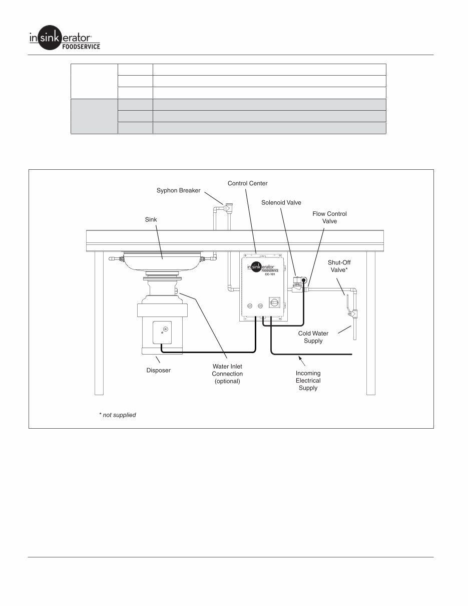
Recommended Installation
Figure 5. Recommended Installation
Service Manual 7
Commercial Disposers
PREPARATION FOR REPAIR
DANGER
ELECTRIC SHOCK! Turn off water and
electrical supply. Discharge capacitor with
1000 ohm jumper wire (1 Phase only). Do
not use a screwdriver to discharge or
capacitor may be damaged.
Removing Disposer
1. Turn off electrical supply and water supply to disposer.
2. Disconnect cold water connection from disposer body water
inlet (if connected).
3. Disconnect waste line from disposer.
4. Remove terminal box retaining screw and terminal box cover.
See “Terminal Box & Trim Band” on page 9. Mark motor lead
wires and electrical supply wires, then disconnect wires and
grounding wire from disposer.
NOTE: Make sure sink can bear weight of disposer before legs
are loosened. In some cases, support disposer before loosening
or removing legs.
5. If equipped with legs and legs interfere with removing dis-
poser from mounting flange, pull O-ring down disposer leg,
turn each leg clockwise to raise legs and gain floor clearance.
6. Remove disposer from mounting flange by turning disposer
or loosening bolts as necessary (depending on mounting
flange).
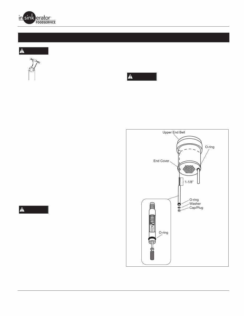
7. To remove legs, remove black cap plug from bottom of sup-
port leg (Figure 6). Insert slotted screwdriver into open end of
leg support tube and turn stud counterclockwise until free of
upper end bell. Pull leg from disposer.
Installing Disposer
ELECTRIC SHOCK! Turn off water and
electrical supply. Discharge capacitor
with jumper wire (1 Phase only).
1. If unit was equipped with legs, insert leg assemblies through
end cover guide holes. Insert screwdriver into open end of leg
support tube and turn stud clockwise to install. Install O-ring,
washer and cap to each leg (Figure 6).
NOTE: On models SS-150 thru SS-200, legs are optional and rec-
ommended where the disposer is mounted to a thin gauge sink
(16 gauge minimum), dish table, using a #5 mounting assembly
or non-InSinkErator mounting adaptors. On models SS-300 and
above, legs are factory installed and recessed on the unit.
2. Attach disposer to the mounting assembly by positioning in
mounting flange and turning disposer into flange or tightening
bolts (depending on specific mounting).
3. Adjust legs so unit is supported evenly. Push O-ring up flush
with bottom of unit.
DANGER
4. Connect electrical supply wires to the motor leads. Refer-
ence the wiring diagram attached to the inside of the terminal
box or the Wiring Diagrams section of the Disposer Control
Center Installation manual.
5. Reinstall terminal box.
ELECTRIC SHOCK! Make sure electrical
wires are not pinched or damaged when
installing terminal box cover.
6. Connect waste line to disposer.
7. Connect cold water supply to disposer body water inlet (if pre-
viously installed).
8. Turn on electrical and water supply.
9. Test the disposer to ensure the cutting elements revolve
and the water flows automatically. Make sure the disposer is
securely mounted and does not leak from any of the connec-
tions.
Figure 6. Disposer Leg
DANGER
You're Reading a Preview
What's Included?
Fast Download Speeds
Online & Offline Access
Access PDF Contents & Bookmarks
Full Search Facility
Print one or all pages of your manual
$28.99
Viewed 13 Times Today


Secure transaction
What's Included?
Fast Download Speeds
Online & Offline Access
Access PDF Contents & Bookmarks
Full Search Facility
Print one or all pages of your manual
$28.99
Whether you're a professional mechanic or a DIY enthusiast, this manual is ideal for repairing your vehicle. It provides model-specific information and is not generic. You can access this manual instantly upon payment completion, eliminating the need to wait for unreliable postal delivery. Additionally, you have the flexibility to print only the necessary pages.


