1999-2000 E-Z-GO Industrial/Workhorse (800/1000/1200) UTV OEM Service & Repair Manual
What's Included?
Lifetime Access
Fast Download Speeds
Online & Offline Access
Access PDF Contents & Bookmarks
Full Search Facility
Print one or all pages of your manual
ELECTRIC AND GASOLINE UTILITY VEHICLES STARTING MODEL YEAR: 1999 OWNER’S MANUAL AND SERVICE GUIDE 28547-G01 ENGLISH English
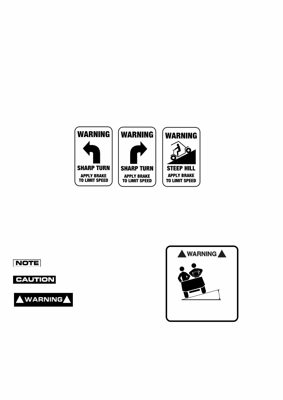
SAFETY NOTES, CAUTIONS AND WARNINGS Throughout this guide NOTE, CAUTION and WARNING will be used. A NOTE indicates a condition that should be observed. A CAUTION indicates a condition that may result in damage to the vehicle. A WARNING indicates a hazardous condition which could result in severe injury or death. Please observe these NOTES, CAUTIONS and WARN- INGS; be aware that servicing a vehicle requires mechanical skill and a regard for conditions that could be hazardous. Improper service or repair may damage the vehicle or render it unsafe. ! ! ! ! < 14 0 DO NOT DRIVE ON GREATER THAN 14 0 INCLINE Read and understand all labels located on the vehicle. For any questions on any of the information, contact an E-Z-GO representative for clarification. Always replace any damaged or missing labels. On steep hills it is possible for vehicles to coast at greater than normal speeds encountered on a flat surface. To prevent loss of vehicle control and possible serious injury, speeds should be limited to no more than the maximum speed on level ground. (See vehicle specification.) Limit speed by applying the service brake. Catastrophic damage to the drive train components due to excessive speed may result from driving the vehicle above specified speed. Damage caused by excessive speed may cause a loss of vehicle control, is costly, is considered abuse and will not be covered under warranty. Use extra caution when towing the vehicle. Do not tow vehicle at speeds in excess of 19 kph. Towing the vehicle at above the recommended speed may result in personal injury and/or damage to the vehicle and other property. If the vehicle is to be used in a commercial environment, signs similar to the ones illustrated should be used to warn of situations that could result in an unsafe coasting condition. Be sure that this manual remains as part of the permanent service record should the vehicle be re-sold.
Read and understand the following warnings before attempting to operate the vehicle: To prevent personal injury or death, observe the following: When vehicle is to be left unattended, engage parking (PARK) brake, move direction selector to neutral (electric vehicles) forward (gasoline vehicles), turn key to ‘OFF’ position and remove key. Drive vehicle only as fast as terrain and safety considerations allow. Consider the terrain and traffic conditions. Consider environmental factors which effect the terrain and the ability to control the vehicle. Avoid driving fast down hill. Sudden stops or change of direction may result in a loss of control. Use service brake to control speed when traveling down an incline. Use extra care and reduced speed when driving on poor surfaces, such as loose dirt, wet grass, gravel, etc. All travel should be directly up or down hills. Use extra care when driving the vehicle across an incline. Stay in designated areas and avoid steep slopes. Use the parking brake (PARK) whenever the vehicle is parked. Keep feet, legs, hands and arms inside vehicle at all times. Avoid extremely rough terrain. Check area behind the vehicle before operating in reverse. Make sure the direction selector is in correct position before attempting to start the vehicle. Slow down before and during turns. All turns should be executed at reduced speed. Always bring vehicle to a complete stop before shifting the direction selector. See GENERAL SPECIFICATIONS for standard vehicle load and seating capacity. Read and understand the following text and warnings before attempting to service vehicle: In any product, components will eventually fail to perform properly as the result of normal use, age, wear or abuse. It is virtually impossible to anticipate all possible compo- nent failures or the manner in which each component may fail. Be aware that a vehicle requiring repair indicates that the vehicle is no longer functioning as designed and there- fore should be considered potentially hazardous. Use extreme care when working on any vehicle. When diag- nosing, removing or replacing any components that are not operating correctly, take time to consider the safety of yourself and others around you should the component move unexpectedly. Some components are heavy, spring loaded, highly cor- rosive, explosive or may produce high amperage or reach high temperatures. Battery acid and hydrogen gas could result in serious bodily injury to the technician/mechanic and bystanders if not treated with the utmost caution. Be careful not to place hands, face, feet or body in a location that could expose them to injury should an unforeseen situation occur. Before working on the vehicle, remove all jewelry (rings, watch, necklaces, etc.). Be sure no loose clothing or hair can contact moving parts. Use care not to touch hot objects. Raise rear of vehicle and support on jack stands before attempting to run or adjust powertrain. Wear eye protection when working on or around the vehicle. In particular, use care when working around batteries, using solvents or compressed air. Hydrogen gas is formed when charging batteries. Do not charge batteries without adequate ventilation. Do not permit open flame or anyone to smoke in an area that is being used for charging batteries. A concentration of 4% hydrogen gas or more is explosive. Engine exhaust gas (carbon monoxide) is deadly. Carbon monoxide is an odorless, colorless gas that is formed as a natural part of incomplete combustion of hydrocarbon fuels. Carbon monoxide is a dangerous gas that can cause unconsciousness and is potentially lethal. The following are symptoms of carbon monoxide inhalation: • Dizziness • Vomiting • Intense Headache • Muscular Twitching • Weakness and Sleepiness • Throbbing in Temples If any of these symptoms are experienced, get fresh air immediately. Never work around or operate a vehicle in an environment that does not ventilate exhaust gases from the area. ! ! ! !
Page i Owner’s Manual and Service Guide OWNER’S MANUAL AND SERVICE GUIDE ELECTRIC AND GASOLINE UTILITY TRUCKS VEHICLES INDUSTRIAL 800E WORKHORSE ® 800E WORKHORSE ® 800LX E WORKHORSE ® 1000E WORKHORSE ® 1000LX INDUSTRIAL 800G WORKHORSE ® 800G WORKHORSE ® 800LX G WORKHORSE ® 1200G WORKHORSE ® 1200LX OASIS™ E-Z-GO Division of Textron reserves the right to make design changes without obligation to make these changes on units previously sold and the information contained in this manual is subject to change without notice. E-Z-GO Division of Textron is not liable for errors in this manual or for incidental or consequential damages that result from the use of the material in this manual. CUSTOMER SERVICE DEPARTMENT OUTSIDE USA PHONE: 010-1-706-798-4311, FAX: 010-1-706-771-4609 E-Z-GO DIVISION OF TEXTRON, INC., P.O.BOX 388, AUGUSTA, GEORGIA USA 30903-0388
Page ii NOTES Owner’s Manual and Service Guide A copy of the International Limited Warranty is located at the end of this manual. The use of non E-Z-GO parts may void the warranty. Overfilling batteries may void the warranty. Tampering with or adjusting the governor to permit vehicle to operate at above factory specifications will void the vehicle warranty. BATTERY PROLONGED STORAGE All batteries will self discharge over time. The rate of self discharge varies depending on the ambient temperature and the age and condition of the batteries. A fully charged battery will not freeze in winter temperatures unless the temperature falls below -60° C. For winter storage, the batteries must be clean, fully charged and disconnected from any source of electrical drain. With electric vehicles, the battery charger and the controller are both sources of electrical drain. For electric vehicles with portable chargers, unplug the battery charger DC plug from the vehicle receptacle. As with all electric vehicles, the batteries must be checked and recharged as required or at a minimum of 30 day intervals.
Page iii TABLE OF CONTENTS Owner’s Manual and Service Guide BEFORE INITIAL USE ............................................................................................................... 1 Preparation of Seats for Service .......................................................................................................................... 1 Fig. 1 Initial Service Chart ...................................................................................................................... 1 Portable Charger Installation for Electric Vehicles ............................................................................................... 1 Fig. 2 Charger Installation ...................................................................................................................... 1 Fig. 3 Charger Receptacle ..................................................................................................................... 2 SERIAL NUMBER PLATE LOCATION ...................................................................................... 2 Fig. 4 Serial Number Plate Location ...................................................................................................... 2 CONTROLS ............................................................................................................................... 2 Key/Light Switch .................................................................................................................................................. 2 Fig. 5 Key/Light Switch .......................................................................................................................... 2 Direction Selector ................................................................................................................................................ 2 Fig. 6 Direction Selector ........................................................................................................................ 3 Accelerator Pedal ................................................................................................................................................ 3 Combination Service and Parking (PARK) Brake Pedal (Excludes 1200) ........................................................... 3 Fig. 7 Accelerator, Brake and Horn ....................................................................................................... 3 Hand Released Parking Brake (1200 Only) ......................................................................................................... 3 Fig. 8 Hand Released Parking Brake .................................................................................................... 3 Horn ..................................................................................................................................................................... 3 Choke (Gasoline Models Only) ............................................................................................................................ 4 Fig. 9 Choke .......................................................................................................................................... 4 Electric Lift Switch ................................................................................................................................................ 4 Fig. 10 Electric Lift Switch ...................................................................................................................... 4 LOAD BED ................................................................................................................................. 5 Fig. 11 Load Bed Warning Label ........................................................................................................... 5 Manual Lift Load Bed Operation .......................................................................................................................... 6 Fig. 12 Manual Lift Latch ....................................................................................................................... 6 Fig. 13 Manual Lift Prop ......................................................................................................................... 6 Electric Lift Load Bed Operation .......................................................................................................................... 6 BEFORE ENTERING VEHICLE ................................................................................................. 6 OPERATING THE VEHICLE ...................................................................................................... 6 Starting the Electric Vehicle ................................................................................................................................. 7 Starting the Gasoline Vehicle .............................................................................................................................. 7 Cold Starting the Gasoline Vehicle ...................................................................................................................... 7 Starting the Vehicle on a Hill ................................................................................................................................ 7 Starting a Gasoline Vehicle with a Discharged Battery ....................................................................................... 8 COASTING ................................................................................................................................. 8 FUEL .......................................................................................................................................... 8 Fig. 14 Fuel Tank Location .................................................................................................................... 8 Fuel Gauge and Indicator Lights .......................................................................................................................... 8 TOWING ..................................................................................................................................... 9 Neutral Lock (Gasoline Vehicles Only) ................................................................................................................ 9 Fig. 15 Neutral Lock ............................................................................................................................... 9 SERVICING THE VEHICLE ....................................................................................................... 9 Break-In (Gasoline Vehicles Only) ..................................................................................................................... 10 Fig. 16 Check Oil Level on Dipstick ..................................................................................................... 10 LIFTING THE VEHICLE ........................................................................................................... 10 Fig. 17 Lifting the Vehicle .................................................................................................................... 10 ROUTINE MAINTENANCE ...................................................................................................... 11 Fig. 18 Lubrication Points .................................................................................................................... 11 REAR AXLE (ELECTRIC VEHICLES) ..................................................................................... 11 Checking the Lubricant Level ............................................................................................................................ 11
Page iv Owner’s Manual and Service Guide TABLE OF CONTENTS Fig. 19 Add, Check and Drain Rear Axle Lubricant on Electric Vehicles ............................................ 11 REAR AXLE (GASOLINE VEHICLES) ..................................................................................... 11 Fig. 20 Add, Check and Drain Rear Axle Lubricant on Gasoline Vehicles .......................................... 12 Checking the Lubricant Level ............................................................................................................................ 12 POWERTRAIN MAINTENANCE FOR GASOLINE VEHICLES ............................................... 12 Direction Selector .............................................................................................................................................. 12 Fig. 21 Shift Cable Adjustment ............................................................................................................ 12 Checking the Oil Level ...................................................................................................................................... 12 Fig. 22 Clean Entire Dipstick ............................................................................................................... 12 Fig. 23 Check Oil Level on Dipstick .................................................................................................... 13 Changing the Oil ............................................................................................................................................... 13 Fig. 24 Oil Viscosity Chart ................................................................................................................... 13 Fig. 25 Clean Top of Engine ............................................................................................................... 13 Fig. 26 Remove Oil Filter .................................................................................................................... 14 Fig. 27 Clean Oil Filter ........................................................................................................................ 14 Fig. 28 Blow Out Oil Filter ................................................................................................................... 14 Fig. 29 Add Engine Oil ........................................................................................................................ 14 AIR CLEANER INSPECTION/REPLACEMENT ....................................................................... 15 Fig. 30 Air Cleaner .............................................................................................................................. 15 STARTER/GENERATOR BELT TENSION .............................................................................. 15 Fig. 31 Checking Belt Tension with Gauge ......................................................................................... 15 Fig. 32 Checking Belt Tension with Finger .......................................................................................... 16 Adjusting the Belt .............................................................................................................................................. 16 Fig. 33 Adjusting Belt Tension ............................................................................................................ 16 AIR INTAKE AND COOLING FINS .......................................................................................... 16 Fig. 34 Cleaning Air Intake .................................................................................................................. 16 Fig. 35 Cleaning the Cooling Fins ....................................................................................................... 16 SPARK PLUGS ........................................................................................................................ 16 Fig. 36 Gapping the Spark Plug .......................................................................................................... 17 BRAKES ................................................................................................................................... 17 Daily Brake Test ................................................................................................................................................ 17 TIRES ....................................................................................................................................... 17 Tire Repair ........................................................................................................................................................ 17 Wheel Installation .............................................................................................................................................. 18 Fig. 37 Wheel Installation .................................................................................................................... 18 PREPARING THE GASOLINE VEHICLE FOR WINTER OR PROLONGED STORAGE ........ 18 LIGHT BULB REPLACEMENT ................................................................................................. 18 CARE AND CLEANING OF THE VEHICLE ............................................................................. 19 VEHICLE CARE PRODUCTS .................................................................................................. 19 VENDING UNIT (OASIS TM ) ...................................................................................................... 20 Warming Unit .................................................................................................................................................... 20 Fig. 38 Thermostat and Bin Drains ..................................................................................................... 20 Cold Bins ........................................................................................................................................................... 20 Cleaning the Vending Unit ................................................................................................................................ 20 Fig. 39 Empty Water from Bins ........................................................................................................... 20 Moving the Vending Unit ................................................................................................................................... 20 Fig. 40 Releasing Canopy Frame ....................................................................................................... 21 Fig. 41 Releasing Mounting Frame ..................................................................................................... 21 Removing the Vending Unit .............................................................................................................................. 21 Fig. 42 Vending Unit ............................................................................................................................ 21 TOP AND WINDSHIELD .......................................................................................................... 22
Page v TABLE OF CONTENTS Owner’s Manual and Service Guide TRAILERING ............................................................................................................................ 22 TORQUE SPECIFICATIONS ................................................................................................... 22 Fig. 44 Torque Specifications .............................................................................................................. 22 HARDWARE ............................................................................................................................ 22 Fig. 43 Bolt Grades .............................................................................................................................. 22 LABELS USED ON VEHICLE .................................................................................................. 23 Fig. 45 Labels/Pictograms ................................................................................................................... 23 PERIODIC SERVICE SCHEDULE ........................................................................................ 24 Fig. 46 Periodic Service Schedule ....................................................................................................... 24 BATTERIES AND CHARGING FOR ELECTRIC VEHICLES .................................................. 26 Safety ................................................................................................................................................................. 26 BATTERY ................................................................................................................................. 26 BATTERY MAINTENANCE ...................................................................................................... 26 At Each Charging Cycle ..................................................................................................................................... 26 Monthly .............................................................................................................................................................. 27 Electrolyte Level and Water ............................................................................................................................... 27 Fig. 47 Correct Electrolyte Level .......................................................................................................... 27 Fig. 48 Water Purity Table ................................................................................................................... 27 Fig. 49 Automatic Watering Gun .......................................................................................................... 28 Cleaning Batteries ............................................................................................................................................. 28 Fig. 50 Preparing Acid Neutralizing Solution ....................................................................................... 28 Battery Replacement ......................................................................................................................................... 28 Fig. 51 Battery Connections ................................................................................................................ 29 Prolonged Storage ............................................................................................................................................. 29 Fig. 52 Freezing Point of Electrolyte .................................................................................................... 29 Battery Charging ................................................................................................................................................ 29 AC Voltage ......................................................................................................................................................... 30 TROUBLESHOOTING ............................................................................................................. 30 Hydrometer ........................................................................................................................................................ 30 Fig. 53 Hydrometer .............................................................................................................................. 31 Using A Hydrometer .......................................................................................................................................... 31 Fig. 54 Hydrometer Temperature Correction ....................................................................................... 32 BATTERY CHARGER MAINTENANCE ................................................................................... 32 Fig. 55 Cleaning Auxiliary Contact in Charger Plug ............................................................................. 32 GENERAL SPECIFICATIONS .................................................................................................. 33 INDUSTRIAL 800E ............................................................................................................................................. 34 WORKHORSE ® 800E ........................................................................................................................................ 35 WORKHORSE ® 800LX E ................................................................................................................................... 36 WORKHORSE ® 1000......................................................................................................................................... 37 WORKHORSE ® 1000LX ................................................................................................................................... 38 INDUSTRIAL 800G............................................................................................................................................. 39 WORKHORSE ® 800G ........................................................................................................................................ 40 WORKHORSE ® 800LX G .................................................................................................................................. 41 WORKHORSE ® 1200......................................................................................................................................... 42 WORKHORSE ® 1200LX .................................................................................................................................... 43 OASIS TM ............................................................................................................................................................. 44 Fig. 56 Vehicle Dimensions ................................................................................................................. 45 Fig. 57 Vehicle Dimensions (LX Models) .............................................................................................. 46 Fig. 58 Vehicle Dimensions (OASIS TM ) ............................................................................................... 47 Fig. 59 Incline Specifications and Turning Clearance Diameter .......................................................... 48 INTERNATIONAL LIMITED WARRANTY ................................................................................. 49 DECLARATION OF CONFORMITY..........................................................................Last 3 pages
Page vi Owner’s Manual and Service Guide TABLE OF CONTENTS Notes:
1999-2000 E-Z-GO Industrial/Workhorse (800/1000/1200) UTV Service & Repair Manual is a comprehensive guide for fixing problems on your UTV. It is useful for both professional mechanics and DIY enthusiasts. The manual covers models including E-Z-GO INDUSTRIAL 800E, E-Z-GO WORKHORSE 800E, E-Z-GO WORKHORSE 800LX E, E-Z-GO WORKHORSE 1000E, E-Z-GO WORKHORSE 1000LX, E-Z-GO INDUSTRIAL 800G, E-Z-GO WORKHORSE 800G, E-Z-GO WORKHORSE 800LX G, E-Z-GO WORKHORSE 1200G, and E-Z-GO WORKHORSE 1200LX.
The manual provides manufacturer-recommended troubleshooting charts and replacement procedures, including step-by-step instructions, clear images, and exploded-view illustrations. It is designed to help you save on repairs, increase your UTV’s reliability, and minimize trips to the repair shop.
This is not a generic repair manual but the OEM repair manual used by professional technicians. It contains every troubleshooting and replacement procedure provided by the manufacturer, including step-by-step instructions, exploded-view illustrations, and clear images. The manual is printable and compatible with various electronic devices, including PC & Mac computers, Android and Apple smartphones & tablets, etc. It requires Adobe Reader (free) for access.
Recently Viewed
5,521,897Happy Clients
2,594,462eManuals
1,120,453Trusted Sellers
15Years in Business
Price:
Actual Price:
1999-2000 E-Z-GO Industrial/Workhorse (800/1000/1200) UTV OEM Service & Repair Manual