6-4 Engine Mechanical - 6.0L Engine 2002 Valve Rocker Arm Cover Removal (Left Side) .......................................................................... 47 Valve Rocker Arm Cover Removal (Right Side) ....................................................................... 48 Valve Rocker Arm and Push Rod Removal .............................................................................. 50 Cylinder Head Removal - Left Side ........................................................................................... 51 Cylinder Head Removal - Right Side ......................................................................................... 51 Valve Lifter Removal .................................................................................................................. 52 Oil Filter, Adapter and Pan Cover Removal .............................................................................. 53 Oil Pan Removal ......................................................................................................................... 54 Engine Front Cover Removal .................................................................................................... 56 Engine Rear Cover Removal ......................................................................................................... 57 Oil Pump, Pump Screen and Deflector Removal ..................................................................... 58 Timing Chain and Sprockets Removal ..................................................................................... 59 Camshaft Removal ..................................................................................................................... 60 Piston, Connecting Rod and Bearing Removal ....................................................................... 61 Crankshaft and Bearings Removal ........................................................................................... 63 Engine Block Plug Removal ...................................................................................................... 65 Engine Block Clean and Inspect ............................................................................................... 69 Cylinder Boring and Honing ...................................................................................................... 70 Boring Procedure ...................................................................................................................................................... 70 Honing Procedure ..................................................................................................................................................... 70 Deglazing Procedure ................................................................................................................................................ 71 Crankshaft and Bearings Clean and Inspect ........................................................................... 72 Cleaning Procedure .................................................................................................................................................. 72 Inspection procedure ................................................................................................................................................ 72 Measuring Main Bearing Clearance .......................................................................................... 76 Measuring Connecting Rod Bearing Clearance ....................................................................................................... 80 Crankshaft Balancer Clean and Inspect .................................................................................. 81 Engine Flywheel Clean and Inspect .......................................................................................... 82 Piston and Connecting Rod Disassemble ............................................................................... 83 Press Fit Piston Pin .................................................................................................................................................. 83 Full-Floating Piston Pin ........................................................................................................................................... 85 Piston, Connecting Rod and Bearings Clean and Inspect ..................................................... 86 Piston and Pin .......................................................................................................................................................... 86 Connecting Rod and Bearings ................................................................................................................................. 89 Measuring Piston Ring End Gap .............................................................................................................................. 91 Piston and Connecting Rod Assemble .................................................................................... 91 Press Fit Piston Pin .................................................................................................................................................. 91 Full-Floating Piston Pin ........................................................................................................................................... 95 Camshaft Bearing Removal ....................................................................................................... 96 Tool Usage Information .............................................................................................................. 97 Bearing, Expander and Expander Driver Information ............................................................................................. 97 Tool Assembly and Operation .................................................................................................................................. 98 Camshaft and Bearings Clean and Inspect .............................................................................. 99 Camshaft Bearing Installation ................................................................................................. 101 Measuring Camshaft Lobe Lift ............................................................................................................................... 101 Timing Chain and Sprockets Clean and Inspect ................................................................... 102 Valve Rocker Arm and Push Rods Clean and Inspect .......................................................... 103 Valve Lifters and Guides Clean and Inspect .......................................................................... 105 Cylinder Head Disassemble .................................................................................................... 106
Engine Engine Mechanical - 6.0L 6-5 2002 Cylinder Head Clean and Inspect ........................................................................................... 108 Valve Guide Reaming/Valve and Seat Grinding ..................................................................... 110 Valve Guide Reaming .............................................................................................................................................. 110 Valve and Seat Grinding ......................................................................................................................................... 112 Cylinder Head Assemble ......................................................................................................... 115 Oil Pump Disassemble ............................................................................................................. 118 Oil Pump Clean and Inspect .................................................................................................... 121 Oil Pump Assemble .................................................................................................................. 123 Engine Front Cover Clean and Inspect .................................................................................. 125 Engine Rear Cover Clean and Inspect ................................................................................... 126 Engine Valley Cover Clean and Inspect .................................................................................. 126 Valve Rocker Arm Cover Clean and Inspect .......................................................................... 127 Oil Pan Clean and Inspect ........................................................................................................ 128 Intake Manifold Clean and Inspect .......................................................................................... 131 Cleaning Procedure ................................................................................................................................................ 131 Inspection Procedure .............................................................................................................................................. 132 Exhaust Manifold Clean and Inspect ...................................................................................... 134 Coolant Air Bleed Pipe Clean and Inspect ............................................................................. 135 Water Pump Clean and Inspect ............................................................................................... 136 Thread Repair ........................................................................................................................... 137 General Thread Repair ............................................................................................................................................ 137 Cylinder Head Bolt Hole Thread Repair ................................................................................................................. 140 Main Cap Bolt Hole Thread Repair .......................................................................................... 144 Service Prior to Assembly ....................................................................................................... 148 Engine Block Plug Installation ................................................................................................ 150 Crankshaft and Bearings Installation ..................................................................................... 153 Piston, Connecting Rod and Bearing Installation ................................................................. 156 Piston Selection ...................................................................................................................................................... 156 Installation Procedure ............................................................................................................................................ 158 Camshaft Installation ............................................................................................................... 161 Timing Chain and Sprockets Installation ............................................................................... 162 Oil Pump, Pump Screen and Deflector Installation ................................................................ 164 Engine Rear Cover Installation ............................................................................................... 165 Crankshaft Rear Oil Seal Installation ...................................................................................... 168 Engine Front Cover Installation .............................................................................................. 168 Crankshaft Front Cover Oil Seal Installation .......................................................................... 170 Oil Pan Installation .................................................................................................................... 171 Oil Filter, Adapter and Pan Cover Installation ......................................................................... 174 Valve Lifter Installation ............................................................................................................. 175 Cylinder Head Installation (Left Side) ..................................................................................... 176 Cylinder Head Installation (Right Side) ................................................................................... 178 Valve Rocker Arm and Push Rod Installation ........................................................................ 180 Valve Rocker Arm Cover Installation - Left ............................................................................. 181 Valve Rocker Arm Cover Installation - Right .......................................................................... 182 Engine Valley Cover Installation .............................................................................................. 184 Coolant Air Bleed Pipe Installation ......................................................................................... 185 Intake Manifold Installation ...................................................................................................... 187 Fuel Rail and Injectors Installation .......................................................................................... 190 Water Pump Installation ........................................................................................................... 191
6-6 Engine Mechanical - 6.0L Engine 2002 Throttle Body Installation ........................................................................................................ 191 Exhaust Manifold Installation - Left ......................................................................................... 192 Exhaust Manifold Installation - Right ...................................................................................... 193 Clutch Pilot Bearing Installation .............................................................................................. 194 Oil Level Indicator and Tube Installation ................................................................................. 194 Engine Flywheel Installation .................................................................................................... 195 Crankshaft Balancer Installation ............................................................................................. 197 Description and Operation ................................................... 200 Engine Component Description ............................................................................................. 200 Camshaft and Drive System ................................................................................................................................... 200 Crankshaft ............................................................................................................................................................... 200 Cylinder Heads ........................................................................................................................................................ 200 Engine Block ........................................................................................................................................................... 201 Exhaust Manifolds .................................................................................................................................................. 201 Intake Manifold ........................................................................................................................................................ 201 Oil Pan ..................................................................................................................................................................... 201 Piston and Connecting Rod Assembly .................................................................................................................. 201 Valve Rocker Arm Cover Assemblies ..................................................................................................................... 201 Valve Train ............................................................................................................................................................... 201 Product Information ................................................................................................................. 201 Torque Values and/or Fastener Tightening Strategies .......................................................................................... 201 Disassembly and Assembly Procedure Revisions ................................................................................................ 201 Engine Mechanical Diagnostic Procedure Revisions ........................................................................................... 201 Lubrication Description ........................................................ 202 Lubrication Flow Schematic .................................................................................................... 202 Lower Front of Engine ............................................................................................................. 203 Separating Parts ....................................................................................................................... 204 Cleanliness and Care ............................................................................................................... 204 Replacing Engine Gaskets ...................................................................................................... 204 Gasket Reuse and Applying Sealant ...................................................................................................................... 204 Separating Components ......................................................................................................................................... 204 Cleaning Gasket Surfaces ....................................................................................................................................... 204 Assembling Components ....................................................................................................................................... 204 Use of RTV and Anaerobic Sealer .......................................................................................... 205 Sealant Types .......................................................................................................................................................... 205 Aerobic Type Room Temperature Vulcanizing (RTV) Sealant ............................................................................... 205 Anaerobic Type Gasket Eliminator Sealant ........................................................................................................... 205 Anaerobic Type Threadlock Sealant ....................................................................................................................... 206 Anaerobic Type Pipe Sealant .................................................................................................................................. 206 Tools and Equipment ............................................................................................................... 206 Special Tools ......................................................................... 207
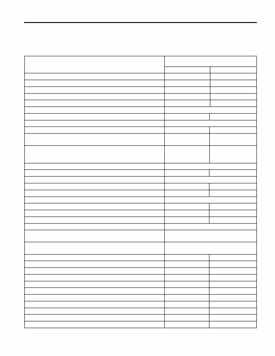
Engine Engine Mechanical - 6.0L 6-7 2002 Engine Mechanical - 6.0L Specifications Fastener Tightening Specifications Specification Application Metric English Accelerator Control Cable Bracket Bolts 10 N•m 89 lb in Camshaft Retainer Bolts 25 N•m 18 lb ft Camshaft Sensor Bolt 25 N•m 18 lb ft Camshaft Sprocket Bolts 35 N•m 26 lb ft Connecting Rod Bolts-First Design (First Pass) 20 N•m 15 lb ft Connecting Rod Bolts-First Design (Final Pass) 60 degrees Connecting Rod Bolts-Second Design (First Pass) 20 N•m 15 lb ft Connecting Rod Bolts-Second Design (Final Pass) 75 degrees Coolant Temperature Gauge Sensor 20 N•m 15 lb ft Crankshaft Balancer Bolt (Installation Pass-to Ensure the Balancer is Completely Installed 330 N•m 240 lb ft Crankshaft Balancer Bolt (First Pass-Install a NEW Bolt After the Installation Pass and Tighten as Described in the First and Final Passes) 50 N•m 37 lb ft Crankshaft Balancer Bolt (Final Pass) 140 degrees Crankshaft Bearing Cap Bolts (Inner Bolts-First Pass in Sequence) 20 N•m 15 lb ft Crankshaft Bearing Cap Bolts (Inner Bolts-Final Pass in Sequence) 80 degrees Crankshaft Bearing Cap Side Bolts 25 N•m 18 lb ft Crankshaft Bearing Cap Bolts (Outer Studs-First Pass in Sequence) 20 N•m 15 lb ft Crankshaft Bearing Cap Bolts (Outer Studs-Final Pass in Sequence) 51 degrees Crankshaft Oil Deflector Nuts 25 N•m 18 lb ft Crankshaft Position Sensor Bolt 25 N•m 18 lb ft Cylinder Head Bolts (First Pass-all M11 Bolts in Sequence) 30 N•m 22 lb ft Cylinder Head Bolts (Second Pass-all M11 Bolts in Sequence) 90 degrees Cylinder Head Bolts (Final Pass-all M11 Bolts in Sequence-Excluding the Medium Length Bolts at the Front and Rear of Each Cylinder Head) 90 degrees Cylinder Head Bolts (Final Pass-all M11 Medium Length Bolts at the Front and Rear of Each Cylinder Head in Sequence) 50 degrees Cylinder Head Bolts (M8 Inner Bolts in Sequence) 30 N•m 22 lb ft Cylinder Head Coolant Plug 20 N•m 15 lb ft Engine Block Coolant Drain Plugs 60 N•m 44 lb ft Engine Block Heater 40 N•m 30 lb ft Engine Block Oil Gallery Plugs 60 N•m 44 lb ft Engine Coolant Air Bleed Pipe Bolts 12 N•m 106 lb in Engine Flywheel Bolts (First Pass) 20 N•m 15 lb ft Engine Flywheel Bolts (Second Pass) 50 N•m 37 lb ft Engine Flywheel Bolts (Final Pass) 100 N•m 74 lb ft Engine Front Cover Bolts 25 N•m 18 lb ft Engine Rear Cover Bolts 25 N•m 18 lb ft
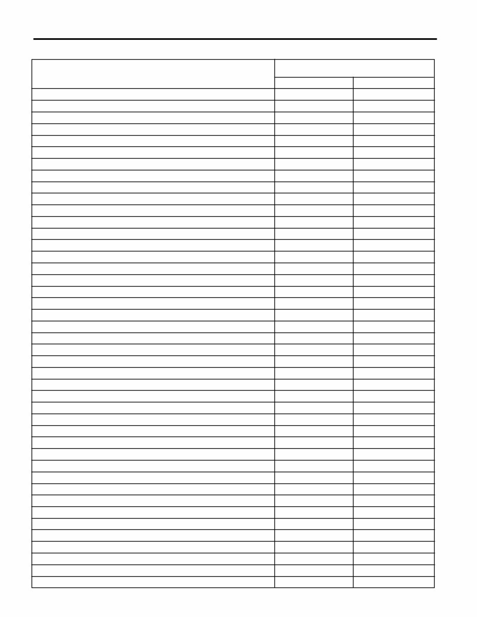
6-8 Engine Mechanical - 6.0L Engine 2002 Fastener Tightening Specifications (cont’d) Specification Application Metric English Engine Service Lift Bracket M10 Bolts 50 N•m 37 lb ft Engine Service Lift Bracket M8 Bolt 25 N•m 18 lb ft Engine Sight Shield Bolts 10 N•m 89 lb in Engine Sight Shield Bracket Bolts 5 N•m 45 lb in Engine Valley Cover Bolts 25 N•m 18 lb ft Exhaust Manifold Bolts (First Pass) 15 N•m 11 lb ft Exhaust Manifold Bolts (Final Pass) 25 N•m 18 lb ft Exhaust Manifold Heat Shield Bolts 9 N•m 80 lb in Fuel Rail Bolts 10 N•m 89 lb in Fuel Rail Crossover Tube Bolts 3.8 N•m 34 lb in Fuel Rail Stop Bracket Bolt 50 N•m 37 lb ft Ignition Coil-to-Bracket Bolts 8 N•m 71 lb in Ignition Coil Bracket-to-Valve Rocker Arm Cover Studs 12 N•m 106 lb in Intake Manifold Bolts (First Pass in Sequence) 5 N•m 44 lb in Intake Manifold Bolts (Final Pass in Sequence) 10 N•m 89 lb in Intake Manifold Wiring Harness Stud 10 N•m 89 lb in Knock Sensors 20 N•m 15 lb ft Oil Filter 30 N•m 22 lb ft Oil Filter Fitting 55 N•m 40 lb ft Oil Level Indicator Tube Bolt 25 N•m 18 lb ft Oil Level Sensor 13 N•m 115 lb in Oil Pan Baffle Bolts 12 N•m 106 lb in Oil Pan Closeout Cover Bolt (Left Side) 9 N•m 80 lb in Oil Pan Closeout Cover Bolt (Right Side) 9 N•m 80 lb in Oil Pan Cover Bolts 12 N•m 106 lb in Oil Pan Drain Plug 25 N•m 18 lb ft Oil Pan M8 Bolts (Oil Pan-to-Engine Block and Oil Pan-to-Front Cover) 25 N•m 18 lb ft Oil Pan M6 Bolts (Oil Pan-to-Rear Cover) 12 N•m 106 lb in Oil Pressure Sensor 20 N•m 15 lb ft Oil Pump-to-Engine Block Bolts 25 N•m 18 lb ft Oil Pump Cover Bolts 12 N•m 106 lb in Oil Pump Relief Valve Plug 12 N•m 106 lb in Oil Pump Screen Nuts 25 N•m 18 lb ft Oil Pump Screen-to-Oil Pump Bolt 12 N•m 106 lb in Spark Plugs-New 20 N•m 15 lb ft Spark Plugs-All Subsequent Installations 15 N•m 11 lb ft Throttle Body Nuts 10 N•m 89 lb in Throttle Body Studs 6 N•m 53 lb in Valve Lifter Guide Bolts 12 N•m 106 lb in Valve Rocker Arm Bolts 30 N•m 22 lb ft Valve Rocker Arm Cover Bolts 12 N•m 106 lb in Water Inlet Housing Bolts 15 N•m 11 lb ft Water Pump Bolts (First Pass) 15 N•m 11 lb ft
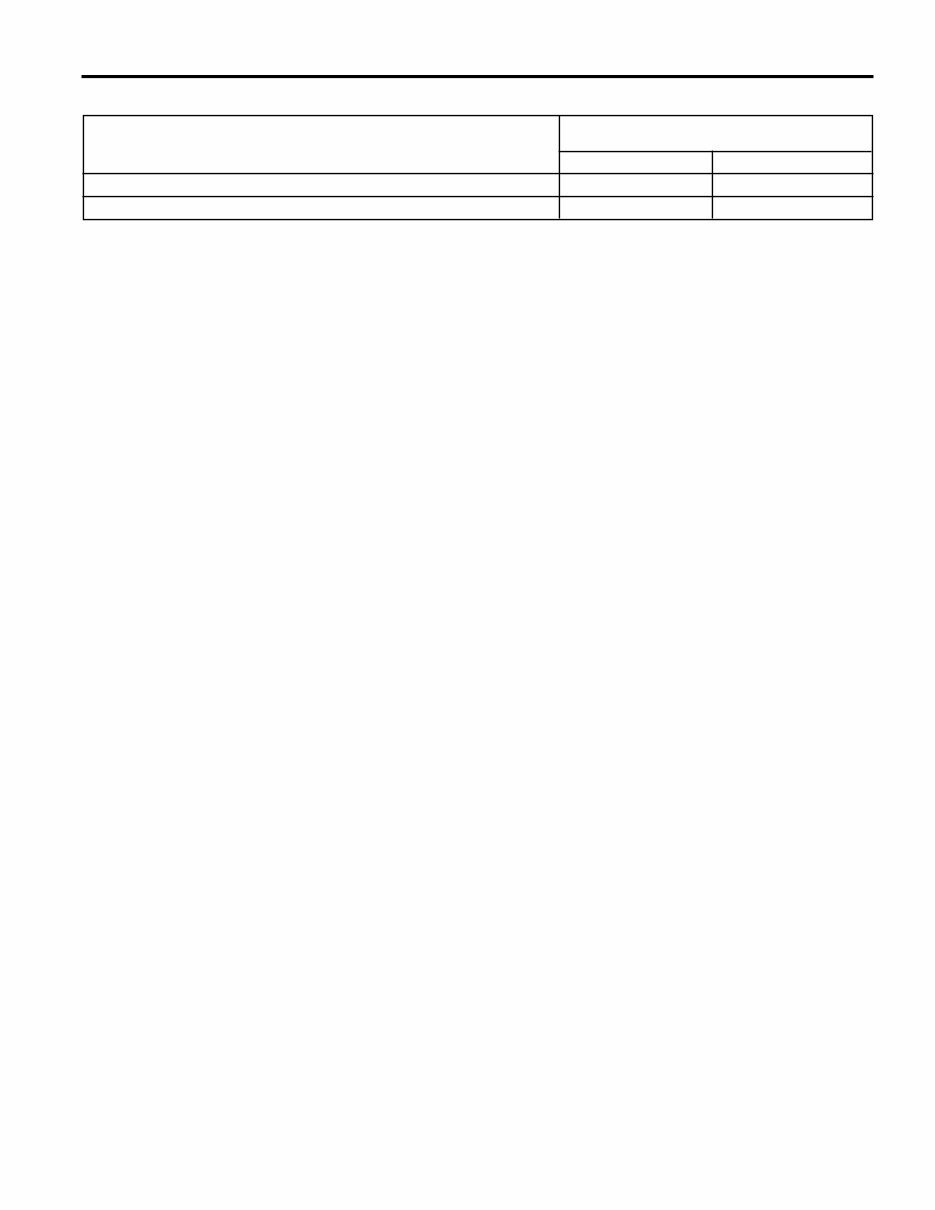
Engine Engine Mechanical - 6.0L 6-9 2002 Fastener Tightening Specifications (cont’d) Specification Application Metric English Water Pump Bolts (Final Pass) 30 N•m 22 lb ft Water Pump Cover Bolts 15 N•m 11 lb ft
6-10 Engine Mechanical - 6.0L Engine 2002 Engine Mechanical Specifications Specification Application Metric English General Data Engine Type V8 Displacement 6.0L 364 CID Bore 101.618-101.636 mm 4.0007-4.0014 in Stroke 92.0 mm 3.622 in Compression Ratio - LQ4 9.40:1 Compression Ratio - LQ9 10.0:1 Firing Order 1-8-7-2-6-5-4-3 Spark Plug Gap 1.524 mm 0.060 in Lubrication System Oil Capacity (without Oil Filter Change) 4.73 Liters 5.0 Quarts Oil Capacity (with Oil Filter Change) 5.68 Liters 6.0 Quarts 41 kPa at 6.0 psig at 1,000 engine rpm 1,000 engine rpm Oil Pressure (Minimum-Hot) 124 kPa at 18.0 psig at 2,000 engine rpm 2,000 engine rpm 165 kPa at 24.0 psig at 4,000 engine rpm 4,000 engine rpm Oil Type 5W-30 Camshaft End Play 0.025-0.305 mm 0.001-0.012 in Journal Diameter 54.99-55.04 mm 2.164-2.166 in Journal Diameter Out-of-Round 0.025 mm 0.001 in Lobe Lift (Exhaust) 7.13 mm 0.281 in Lobe Lift (Intake) 6.96 mm 0.274 in Runout (Measured at the Intermediate Journals) 0.05 mm 0.002 in Connecting Rod Connecting Rod Bearing Bore Diameter 56.505-56.525 mm 2.224-2.225 in Connecting Rod Bearing Bore Out-of-Round - LQ4 0.004-0.008 mm 0.00015-0.0003 in Connecting Rod Bearing Bore Out-of-Round - LQ9 0.006 mm 0.00023 in Connecting Rod Bearing Clearance (Production) 0.023-0.065 mm 0.0009-0.0025 in Connecting Rod Bearing Clearance (Service Limit) 0.023-0.076 mm 0.0009-0.003 in Connecting Rod Side Clearance 0.11-0.51 mm 0.00433-0.02 in Crankshaft Crankshaft Bearing Clearance (Production) 0.020-0.052 mm 0.0008-0.0021 in Crankshaft Bearing Clearance (Service Limit) 0.020-0.065 mm 0.0008-0.0025 in Crankshaft Connecting Rod Journal Diameter (Production) 53.318-53.338 mm 2.0991-2.0999 in Crankshaft Connecting Rod Journal Diameter (Service Limit) 53.308 mm (Minimum) 2.0987 in (Minimum) Crankshaft Connecting Rod Journal Taper (Production) 0.005 mm (Maximum for 1/2 0.0002 in (Maximum for 1/2 of the Journal Length) of the Journal Length) Crankshaft Connecting Rod Journal Taper (Service Limit) 0.02 mm (Maximum) 0.00078 in (Maximum) Crankshaft Connecting Rod Journal Out-of-Round (Production) 0.005 mm 0.0002 in Crankshaft Connecting Rod Journal Out-of-Round (Service Limit) 0.01 mm 0.0004 in Crankshaft End Play 0.04-0.2 mm 0.0015-0.0078 in Crankshaft Main Journal Diameter (Production) 64.993-65.007 mm 2.558-2.559 in Crankshaft Main Journal Diameter (Service Limit) 64.993 mm 2.558 in Crankshaft Main Journal Out-of-Round (Production) 0.003 mm 0.0001 in Crankshaft Main Journal Out-of-Round (Service Limit) 0.008 mm 0.0003 in Crankshaft Main Journal Taper (Production) 0.01 mm 0.0004 in Crankshaft Main Journal Taper (Service Limit) 0.02 mm 0.00078 in Crankshaft Reluctor Ring Runout (Measured 1.0 mm (0.04 in) Below the Tooth Diameter) 0.7 mm (Maximum) 0.028 in (Maximum) Crankshaft Runout (at Rear Flange) 0.05 mm (Maximum) 0.002 in (Maximum) Crankshaft Thrust Wall Runout 0.025 mm 0.001 in
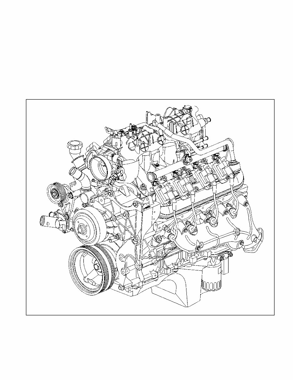
The GM 6.0L V8 Engines (LQ4/LQ9) Service & Repair Manual provides comprehensive service procedures and technical data for GM’s durable Gen III/IV truck engines. Designed for professional technicians and experienced rebuilders, this guide includes critical information for maintaining and overhauling both standard-duty (LQ4) and high-output (LQ9) 6.0L powerplants.
The manual details full mechanical service of the engine assembly, including step-by-step removal and installation procedures, diagnostic techniques, factory torque values, and inspection guides. From crankshaft to camshaft, it ensures precision and factory-correct reassembly every time.
Content Overview:
Torque specs and tightening sequences
Cylinder head and valve train servicing
Crankshaft and piston removal/installation
Timing chain and camshaft procedures
Lubrication system flow and diagnostics
Engine block cleaning and inspection
Machining specs and reassembly procedures
Perfect for engine shops, high-performance builders, or anyone restoring a GM 6.0L V8, this manual ensures accuracy and reliability in every repair.
Language: English Printable: Yes Compatibility: Windows, macOS, iOS, Android Requirements: Any standard PDF reader (e.g., Adobe Reader)
Recently Viewed
5,521,897Happy Clients
2,594,462eManuals
1,120,453Trusted Sellers
15Years in Business
Price:
Actual Price:
GM 6.0L V8 Engines (LQ4/LQ9) Service & Repair Manual