

Caterpillar TH360B & TH560B Telehandler OEM Service & Repair Manual
What's Included?
Fast Download Speeds
Online & Offline Access
Access PDF Contents & Bookmarks
Full Search Facility
Print one or all pages of your manual

Section Title Manual No.
Service Manual Contents 31200265
Torque Specifications 31200268
Engine
Disassembly & Assembly Engine Supplement 31200299
Power Train
Systems Operation, Testing & Adjusting Power Train 31200270
Disassembly & Assembly Power Train 31200300
Vehicle Systems
Schematic Hydraulic System 31200304
Systems Operation, Testing & Adjusting Hydraulic System 31200302
Systems Operation, Testing & Adjusting Steering System 31200273
Systems Operation, Testing & Adjusting Brake System 31200274
Machine Components Specs Machine Systems 31200306
Disassembly & Assembly Machine Systems 31200308
Electrical Systems
Schematic - TH360B Electrical System 31200310
Schematic - TH560B Electrical System 31200311
Machine Troubleshooting
Hydrostatic Transmission
Electronic Control System
31200279
Systems Operation, Testing & Adjusting LSI System 31200280
Systems Operation, Testing & Adjusting Monitoring System 31200281
TH360B & TH560B
Telehandler Service Manual
S/N TBH00100 & After
S/N TBP00100 & After
31200264
31200265 A

Specifications
31200268
December 15, 2006
Torque Specifications - TH220B, TH330B,
TH360B, TH560B & TH580B Telehandlers
S/N TBF00100 & After
S/N TBG00100 & After
S/N TBH00100 & After
S/N TBP00100 & After
S/N TBJ00100 & After

Important Safety Information
Most accidents that involve product operation, maintenance and repair are caused by failure to observe
basic safety rules or precautions. An accident can often be avoided by recognizing potentially hazardous
situations before an accident occurs. A person must be alert to potential hazards. This person should also
have the necessary training, skills and tools to perform these functions properly.
Improper operation, lubrication, maintenance or repair of this product can be dangerous and
could result in injury or death.
Do not operate or perform any lubrication, maintenance or repair on this product, until you have
read and understood the operation, lubrication, maintenance and repair information.
Safety precautions and warnings are provided in this manual and on the product. If these hazard warnings
are not heeded, bodily injury or death could occur to you or to other persons.
The hazards are identified by the "Safety Alert Symbol" and followed by a "Signal Word" such as
"DANGER", "WARNING" or "CAUTION". The Safety Alert "WARNING" label is shown below.
The meaning of this safety alert symbol is as follows:
Attention! Become Alert! Your Safety is Involved.
The message that appears under the warning explains the hazard and can be either written or pictorially
presented.
Operations that may cause product damage are identified by "NOTICE" labels on the product and in
this publication.
Caterpillar cannot anticipate every possible circumstance that might involve a potential hazard.
The warnings in this publication and on the product are, therefore, not all inclusive. If a tool,
procedure, work method or operating technique that is not specifically recommended by Caterpillar
is used, you must satisfy yourself that it is safe for you and for others. You should also ensure that
the product will not be damaged or be made unsafe by the operation, lubrication, maintenance or
repair procedures that you choose.
The information, specifications, and illustrations in this publication are on the basis of information that was
available at the time that the publication was written. The specifications, torques, pressures,
measurements, adjustments, illustrations, and other items can change at any time. These changes can
affect the service that is given to the product. Obtain the complete and most current information before you
start any job. Caterpillar
®
dealers have the most current information available.
When replacement parts are required for this
product Caterpillar recommends using
Caterpillar replacement parts or parts with
equivalent specifications including, but not
limited to, physical dimensions, type, strength
and material.
Failure to heed this warning can lead to
premature failures, product damage, personal
injury or death.

31200268 1
Table of Contents
Table of Contents
Specifications Section
General Information .............................................. 3
Introduction to Torque ...................................... 3
Torque-Turn ..................................................... 3
Torque Sequence ............................................ 3
Metric (ISO) Fasteners .......................................... 4
Metric (ISO) Nuts and Bolts ............................. 4
Metric (ISO) Taperlock Studs ........................... 4
Metric (ISO) Machine Screws .......................... 4
Hex Button Head Screw and Set
Screw ............................................................... 4
English (SAE) Fasteners ....................................... 5
English (SAE) Nuts and Bolts .......................... 5
English (SAE) Taperlock Studs ........................ 5
English (SAE) Machine Screws ....................... 5
Hex Button Head Screw and Set Screws......... 6
Ground Engaging Tool (G.E.T.) Fasteners ........... 6
Installation of Fittings ............................................ 7
Installation of Split Flange Couplings ............... 7
Installation of Adjustable STOR Fittings........... 8
Straight Thread O-Ring Fittings ............................ 8
Plugs ................................................................... 10
Straight Thread O-Ring Plugs (Hex Drive) ..... 10
Straight Thread O-Ring Plugs (Socket Drive) 11
Drain Plugs with Straight Thread .................. 11
Straight Thread O-Ring Plugs (Mechanical Joint
Tube Assemblies) .......................................... 11
O-Ring Face Seal Fittings ................................... 12
Bulkhead Nuts ..................................................... 12
Flare Fittings ....................................................... 13
37 Degree Flare Fitting .................................. 13
45 Degree Flare and 45 Degree Inverted Flare
Fittings ........................................................... 13
Air Conditioning Fittings ...................................... 14
Air Brake Fittings ................................................. 14
Tapered Pipe Thread Fittings .............................. 14
Miscellaneous Fittings ......................................... 15
Hi Duty Tube Fittings (Shear Sleeve)............. 15
SAE Flareless Fittings .................................... 15
Flex Fittings .................................................... 15
Hose Clamps ....................................................... 15
Worm Drive Band Type Clamps..................... 15
Constant Torque Hose Clamps ...................... 16
Table of

2 31200268
Table of Contents

31200268 3
Specifications Section
Specifications Section
General Information
Mismatched or incorrect fasteners can result in
damage or malfunction, or personal injury.
Take care to avoid mixing metric dimensioned fasteners
and inch dimensioned fasteners.
Introduction to Torque
"Torque" is measured in terms of force and distance.
Force is the amount of pushing or pulling applied at the
end of the lever. Distance is the length of the lever that
is being used. Torque values are given in the following
units: NEWTON meters (Nm), pound inches (lb in), and
pound feet (lb ft)
This manual is intended to provide the operator with a
reference. This manual will provide the standard torque
settings for the following: bolts, nuts, plugs, fittings, and
clamps.
Exceptions to these torques are given in the Service
Manual, if necessary.
Be sure to use a torque wrench that has the proper
range. Torque wrenches must be used properly in
order to ensure that the correct torque is applied.
Always use a smooth pull for torque wrenches. Do not
jerk a torque wrench. Do not use adapters that change
the length of the torque wrench. For the correct use of
your torque wrench, refer to the instructions that were
packaged with your torque wrench.
Prior to installation of any hardware, ensure that
components are in near new condition. Bolts and
threads must not be worn or damaged. Threads must
not have burrs or nicks. Hardware must be free of rust
and corrosion. Clean reused fasteners with a
noncorrosive cleaner. Lightly lubricate the threads of
reused fasteners. Lightly lubricate the mating surface of
the head of reused fasteners. Other applications for
lubricating fasteners may also be specified in the
Service Manual. The Service Manual may also specify
the use of sealants and compounds.
Note: Do not use sealants that are not specified in
the Service Manual. Do not use compounds that
are not specified in the Service Manual. Clean old
compound from the bolt and from the hole before
installation.
Torque-Turn
The torque-turn method is used when precise control
over clamping force is required. There is an initial
torque and an additional turn. The initial torque is
required to bring all parts of the joint into contact. The
additional turn provides the desired clamping force.
Ensure that all fasteners have been torqued before you
perform the additional turns. Turn the fastener
according to the specified amount. The specified
amount will normally be equal to or greater than 90°.
The specified amount will normally be in 30°
increments. Turns of 120° or 180° are preferred. Turns
of 120° or 180° are easily measured by the points of
the hex head of the fastener. Lubrication may be
specified in order to reduce the effort that is required for
the final turn. The use of the torque-turn method will
allow the following:
• Increase the life of the fastener.
• Maximize the potential clamping force of a fastener.
Typical applications are the following:
• Track bolts
• Sprocket bolts
• Connecting rod bolts
• Engine Cylinder Heads
• Drive Shaft bolts
Note: Too much tension on the bolt will cause the bolt to
be stretched beyond the point of yield. The bolt will be
permanently stretched. The bolt will loosen the grip on
the parts that are being fastened. If the bolt is
tightened again, the bolt will break. Do not reuse bolts
that have been permanently stretched.
Torque Sequence
Unless the bolt tightening sequence is specified by the
Service Manual, the fasteners should be tightened in a
cross pattern. Use Step 1 through Step 5 unless the
tightening sequence is specified:
1. Hand tighten all fasteners. Larger fasteners may
require the use of a small hand wrench.
2. Torque all fasteners to 40% of full torque.
3. Torque all fasteners to 70% of full torque.
4. Torque all fasteners to full torque by using a cross
pattern. Large flanges may require additional
passes.
5. Apply at least one final full torque to all fasteners
in a clockwise direction until all torque is uniform.
Large flanges may require additional passes.
Note: Final torque may be a turn.
4 31200268
Specifications Section
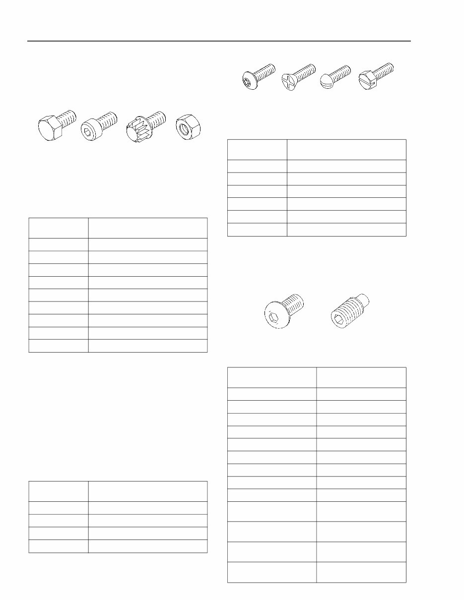
Metric (ISO) Fasteners
Metric (ISO) Nuts and Bolts
Illustration 1 g00909614
Note: The following table has the recommended
standard torque values for Metric nuts and bolts for use
on Perkins engines.
Table 1
Note: The difference between Caterpillar standard
torque values and Perkins standard torque values are
due to different classes of fasteners. Caterpillar uses
class 10.9 fasteners. Perkins uses class 8.8 fasteners.
The different class of fasteners have different tensile
strengths.
Metric (ISO) Taperlock Studs
Note: The following table has the recommended
standard torque values for metric nuts and bolts for use
on Perkins engines.
Table 2
Metric (ISO) Machine Screws
Illustration 2 g00908932
Table 3
Hex Button Head Screw and Set
Screw
Illustration 3 g01186742
Table 4
Thread Size
mm
Torque
M6 5 Nm (44 lb in)
M8 22 Nm (16 lb ft)
M10 44 Nm (32 lb ft)
M12 78 Nm (60 lb ft)
M14 124 Nm (90 lb ft)
M16 177 Nm (130 lb ft)
M18 200 Nm (150 lb ft)
M20 400 Nm (300 lb ft)
M24 790 Nm (580 lb ft)
Thread Size
mm
Torque
M6 5 Nm (44 lb in)
M8 11 Nm (97 lb in)
M10 18 Nm (13 lb ft)
M12 25 Nm (18 lb ft)
Thread Size
mm
Torque
M1.6 0.10 ±0.01 Nm (0.9 ±0.1 lb in)
M2 0.15 ±0.01 Nm (1.3 ±0.1 lb in)
M2.5 0.35 ± 0.05 Nm (3.1 ±0 . 4 lb in)
M3 0.50 ± 0.05 Nm (4.4 ±0 . 4 lb in)
M4 1.70 ± 0.25 Nm (15.0 ± 2.2 lb in)
M5 2.25 ± 0.25 Nm (19.9 ± 2.2 lb in)
Thread Size
mm
Torque
M3 .6± .1 Nm (5 ± 0.9 lb in)
M4 2± .3 N m ( 1 8 ± 3 l b i n )
M5 4± .5 Nm (35 ± 4 lb in)
M6 6± 1 N m ( 5 5 ± 9 l b in)
M8 15 ±3 Nm (11 ± 2 lb ft)
M10 30 ± 7 Nm (22 ± 5 lb ft)
M12 50 ± 10 Nm (37 ± 7 lb ft)
M14 80 ± 15 Nm (60 ± 11 lb ft)
M16 125 ± 20 Nm (90 ± 15 lb ft)
M20 250 ± 40 Nm(185 ± 30 lb ft)
M24
425 ± 50 Nm
(310 ± 37 lb ft)
M30
850 ± 100 Nm
(620 ± 75 lb ft)
M36
1500 ± 200 Nm
(1100 ± 150 lb ft)
31200268 5
Specifications Section
English (SAE) Fasteners
English (SAE) Nuts and Bolts
Illustration 4 g00908911
Table 5
English (SAE) Taperlock Studs
Table 6
English (SAE) Machine Screws
Illustration 5 g00908932
Table 7
Thread Size
Inch
Torque
1/4 12 ± 3 N m ( 9 ± 2 lb ft)
5/16 25 ± 6 Nm (18 ± 4 lb ft)
3/8 47 ± 9 Nm (35 ± 7 lb ft)
7/16 70 ± 15 N m ( 5 0 ± 11 lb ft)
1/2 105 ±20 N m ( 7 5 ± 15 lb ft)
9/16 160 ± 30 N m ( 1 2 0 ± 2 2 lb ft)
5/8 215 ±40 N m ( 1 6 0 ± 30 lb ft)
3/4 370 ± 50 Nm (275 ± 37 lb ft)
7/8 620 ± 80 Nm (460 ± 60 lb ft)
1 900 ± 100 Nm(660±75 lb ft)
1 1/8 1300 ± 150Nm(960± 110 lb ft)
1 1/4 1800 ± 200 Nm (1320 ± 150 lb ft)
1 3/8 2400 ± 300 Nm (1780 ± 220 lb ft)
1 1/2 3100 ± 350 Nm (2280 ± 260 lb ft)
Thread Size
Inch
Standard Torque
1/4 8 ± 3 Nm (6 ± 2 lb ft)
5/16 17 ± 5 Nm (13 ± 4 lb ft)
3/8 35 ± 5 Nm (26 ± 4 lb ft)
7/16 45 ± 10 N m ( 3 3 ± 7 lb ft)
1/2 65 ± 10 N m ( 4 8 ± 7 lb ft)
5/8 110 ±20 N m ( 8 0 ± 15 lb ft)
3/4 170 ± 30 N m ( 1 2 5 ± 2 2 lb ft)
7/8 260 ±40 N m ( 1 9 0 ± 30 lb ft)
1 400 ± 60 Nm (300 ± 44 lb ft)
1 1/8 525 ± 60 Nm (390 ± 44 lb ft)
1 1/4 750 ± 80 Nm (550 ± 60 lb ft)
1 3/8 950 ± 125 Nm(700±90 lb ft)
1 1/2 1200 ± 150Nm(880± 110 lb ft)
Thread Size
No.
Torque
0-80 0.10 ±0.01 Nm (0.9 ±0.1 lb in)
1-64 0.15 ±0.01 Nm (1.3 ±0.1 lb in)
2-56 0.25 ± 0.02 Nm (2.2 ± 0.2 lb in)
3-48 0.35 ± 0.05 Nm (3.1 ± 0.4 lb in)
4-40 0.50 ± 0.05 Nm (4.4 ± 0.4 lb in)
5-40 0.70 ± 0.10 Nm (6.2 ± 0.9 lb in)
6-32 0.90 ± 0.10 Nm (8.0 ± 0.9 lb in)
8-32 1.70 ± 0.25 Nm (15.0 ± 2.2 lb in)
10-24 2.25 ± 0.25 Nm (19.9 ± 2.2 lb in)
12-24 3.40 ± 0.60 Nm (30.1 ± 5.3 lb in)

6 31200268
Specifications Section
Hex Button Head Screw and Set
Screws
Illustration 6 g01186972
Table 8
Ground Engaging Tool (G.E.T.)
Fasteners
Ground Engaging Tools (G.E.T.) are secured by many
types of bolts. Refer to Table 9 for the correct torque for
the following combinations of fasteners for G.E.T.:
• plow bolts and nuts
• hex head bolts and nuts
Table 9
(1) These values are only for Caterpillar bolts for cutting edges.
Thread Size
inch
Torque
#4  .6± .1 Nm(5±0.9 lb in)
#6 & #8 2± . 3 N m ( 1 8 ± 3 lb in)
#10  4± . 5 N m ( 3 5 ± 4 lb in)
1/4 6± 1 N m ( 5 5 ± 9 lb in)
5/16 13±3Nm(115±27 lbin)
3/8 25±6Nm(18±4 lb ft)
7/16 40±8Nm(20±6 lb ft)
1/2 60 ± 1 2 N m ( 4 4 ± 9 l b f t )
9/16 85 ± 1 5 N m ( 6 5 ± 11 lb ft)
5/8 115±20Nm(85± 15 lb ft)
3/4
200 ± 40 Nm
(150 ± 30 lb ft)
7/8
325 ± 40 Nm
(240 ± 30 lb ft)
1
500 ± 65 Nm
(370 ± 48 lb ft)
1 1/8
700 ± 90 Nm
(520 ± 65 lb ft)
1 1/4
1000 ± 125 Nm
(740 ± 90 lb ft)
1 3/8
1300 ± 150 Nm
(960 ± 110 lb ft)
1 1/2
1700 ± 200 Nm
(1260 ± 150 lb ft)
Thread Size Torque(1)
Inch Nm lb ft
5/8 inch 270 ± 40 200 ± 30
3/4 inch 475 ± 60 350 ± 45
7/8 inch 750 ± 90 550 ± 65
1 inch 1150 ± 150 850 ± 110
1 1/4 inch 2300 ± 300 1700 ± 220

31200268 7
Specifications Section
Personal injury can result when installing plow bolts.
The appropriate safety equipment must be worn when
striking the plow bolts. To avoid injury to your eyes and
ears, wear protective glasses and hearing protection
during this procedure.
Illustration 7 g00909058
Plow bolts must be installed properly. Refer to the
following procedure for the correct installation of plow
bolts.
1. Clean all surfaces that contact the bolt. Remove
all occurrences of the following conditions:rust,
paint, nicks, and burrs
2. Tighten the nut to the correct torque. Refer to
Table 9 for the correct torque.
3. Use a hammer to strike the head of the bolt. The
bolt must be struck with significant force.
Note: The head of the bolt may be recessed below the
mounting surface. Use a suitable punch in order to
transfer the hammer blow to the bolt head.
4. Tighten the nut to the correct torque. Refer to
Table 9 for the correct torque.
Installation of Fittings
Note: The tightening sequence of the fasteners that
attach a tube assembly or hose assembly to the
machine is very critical to the proper function of the
machine. The sealing surfaces of the tube assembly or
hose assembly should be secured squarely. The
sealing surfaces of the tube assembly or hose assembly
should be tightened to the serviced component (control
valve, cylinder, hydraulic motor, etc). Perform this
procedure prior to the final tightening of any clamps or
clips that are used in order to fasten the tube
assembly or the hose assembly to the machine.
Fittings have different connections. Fittings may have
two completely different ends. Be sure to use the
proper torque for the end of the fitting that is used. The
following list contains some common types of fittings.
• Straight Thread O-Ring (STOR)
• Adjustable Straight Thread O-Ring (STOR)
• O-Ring Face Seal (ORFS)
• Tapered Pipe Thread (NPT and NPTF)
• 37 Degree Flare Fitting
• 45 Degree Flare Fitting
• 45 Degree Inverted Flare Fitting
• Split Flange Coupling
Installation of Split Flange
Couplings
1. For a metal tube to hose installation, install the
tube and tighten all bolts finger tight at the rigid
end.
2. Install the hose and tighten all bolts finger tight.
3. Put the hose in a position so that the hose does
not make contact with the machine or with another
hose.
Illustration 8 g00906528
4. Tighten the bolts on both connections to the
proper torque. Follow the prescribed torque
sequence for split flange connections. Refer to
Illustration 8. Add the measurement of gap (A) to
the measurement of gap (B). The total must not
exceed 4.0 mm (0.16 inch).
5. Start the engine.
6. Move the implement control levers to all of the
positions.
7. Look at the hose during movement of the
implement. Ensure that the hose is not in contact
with the machine or with other hoses.
Note: For hoses that cross an articulation hitch, check
for contact during articulation. For hoses that connect to
the steering system, check for contact during steering.
8. Shut off the engine.
9. If the hose contacts other hoses or the machine
during the test, loosen the bolts and reposition
the hose. Repeat steps 3 through 8 until there is
no contact.
You're Reading a Preview
What's Included?
Fast Download Speeds
Online & Offline Access
Access PDF Contents & Bookmarks
Full Search Facility
Print one or all pages of your manual
$27.99
Viewed 77 Times Today


Secure transaction
What's Included?
Fast Download Speeds
Online & Offline Access
Access PDF Contents & Bookmarks
Full Search Facility
Print one or all pages of your manual
$27.99
The Caterpillar CAT Factory Service Manual is an essential resource for both professional mechanics and DIY enthusiasts. This comprehensive manual provides detailed technical information, diagrams, and instructions for the maintenance, repair, and troubleshooting of Caterpillar CAT vehicles. Whether you are working on the engine, transmission, electrical system, or hydraulic components, this manual offers in-depth guidance to ensure the job is done right. With its clear and concise format, the manual is designed to assist users in efficiently addressing a wide range of mechanical issues. It is available in .PDF format, making it easily accessible for reference whenever needed.


