

Bosch VE Fuel Pump 4-390 Engines
What's Included?
Fast Download Speeds
Online & Offline Access
Access PDF Contents & Bookmarks
Full Search Facility
Print one or all pages of your manual
Section
3415
BOSCH MODEL VE FUEL INJECTION PUMP
Pump Drive Gear, Fuel Shutoff Solenoid,
Primer Pump and Pump Timing
4-390 Diesel Engine
IMPORTANT: This engine was made using the metric measurement system.
All measurements and checks must be made with metric tools to make sure of
an a accurate reading when inspecting parts.
CASE CORPORATION
700 State Street
Racine, WI 53404 U.S.A.
CASE CANADA CORPORATION
© 1999 Case Corporation
450 Sherman Avenue
Rac 7-37145 Printed in U.S.A.
Hamilton. ON L8N 4C4 CANADA
February, 1991 (Revised May, 1999)
3415-2
TABLE OF CONTENTS
SPECIALTOOLS
........................................................................................................................................................2
SPECIALTORQUES ....................................................................................................................................................
VE Injection Pump
LockTiming Chart .................................................................................................................................................... 3
TROUBLESHOOTINGGUIDE
....................................................................................................................................... 4
FUELINJECTION PUMP .............................................................................................................................................. 5
Removal.................................................................................................................................................................
Installation.............................................................................................................................................................. 7
INJECTIONPUMP GEAR ............................................................................................................................................. 8
Removal.................................................................................................................................................................
8
Installation............................................................................................................................................................
11
INJECTIONPUMP TIMING .........................................................................................................................................
12
FUELSHUT-OFF SOLENOID ......................................................................................................................................
17
Removaland Disassembly ......................................................................................................................................
17
Assemblyand
Installation ........................................................................................................................................
18
PRIMERPUMP ......................................................................................................................................................... 18
Removal............................................................................................................................................................... 18
Installation............................................................................................................................................................ 19
TIMINGLOCKING PIN ............................................................................................................................................... 19
Removal............................................................................................................................................................... 19
Installation............................................................................................................................................................ 20
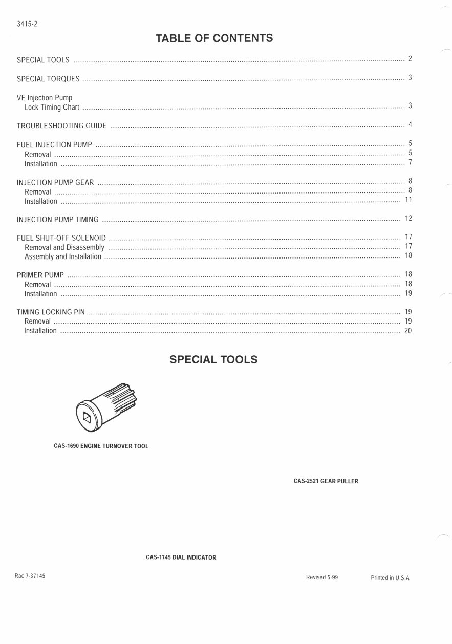
SPECIAL TOOLS
CAS-1690 ENGINE TURNOVER TOOL
CAS-2521 GEAR PULLER
CAS-1145 DIAL INDICATOR
Rac 7-31145
Revised 5-99 Printed in U.S.A
3415-3
SPECIAL TORQUES
Injection Pump Mounting Bolts ........................................................................................................................................ 21 to 27 Nm
Injection Pump Drive Gear Nut ........................................................................................................................................ 59 to 71 Nm
FuelLine Inlet Bolt .......................................................................................................................................................... 22 to 28 Nm
FuelShut-off Solenoid .............................................................................................................................................................. 43 Nm
LeakOff Fitting ................................................................................................................................................................ 1310 17 Nm
Injection Pump Lock Bolt, Lock Position ........................................................................................................................... 2] to 33 Nm
Injection Pump Lock Bolt, Unlock Position ....................................................................................................................... 12 to 14 Nm
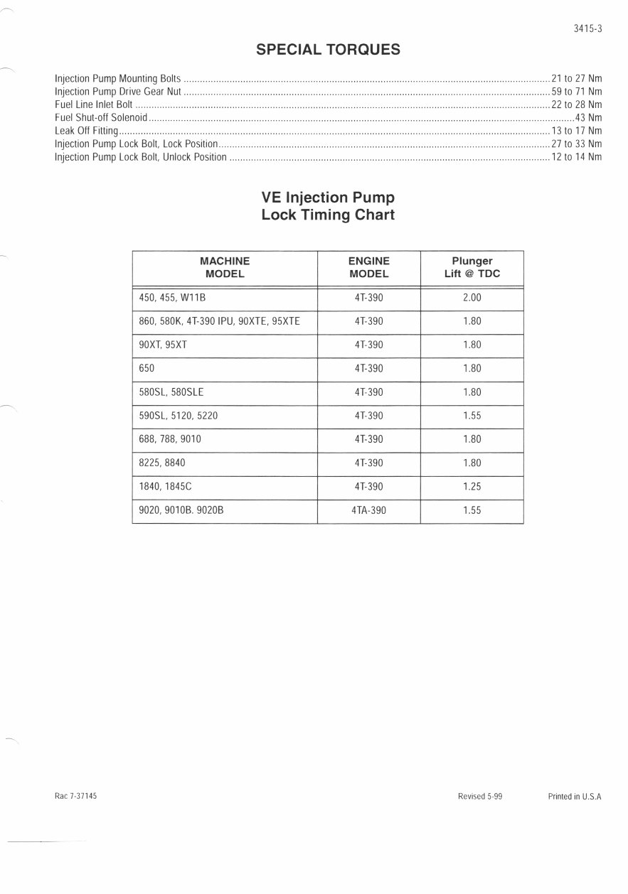
VE Injection Pump
Lock Timing Chart
MACHINE
MODEL
ENGINE
MODEL
Plunger
Lift @ TDC
450, 455, W11B 41-390 2.00
860, 580K, 4T-390 IPU, 9OXTE, 95XTE 4T-390 1.80
90XT, 95XT 41-390 1.80
650 41-390 1.80
580SL, 58OSLE 41-390 1.80
590SL, 5120, 5220 41-390 1.55
688, 788, 9010 41-390 1.80
8225, 8840 41-390 1.80
1840,1845C 41-390 1.25
9020, 9010B. 9020B 4TA-390 1.55
Rac 7-37145 Revised 5-99 Printed in U.S.A
3415-4
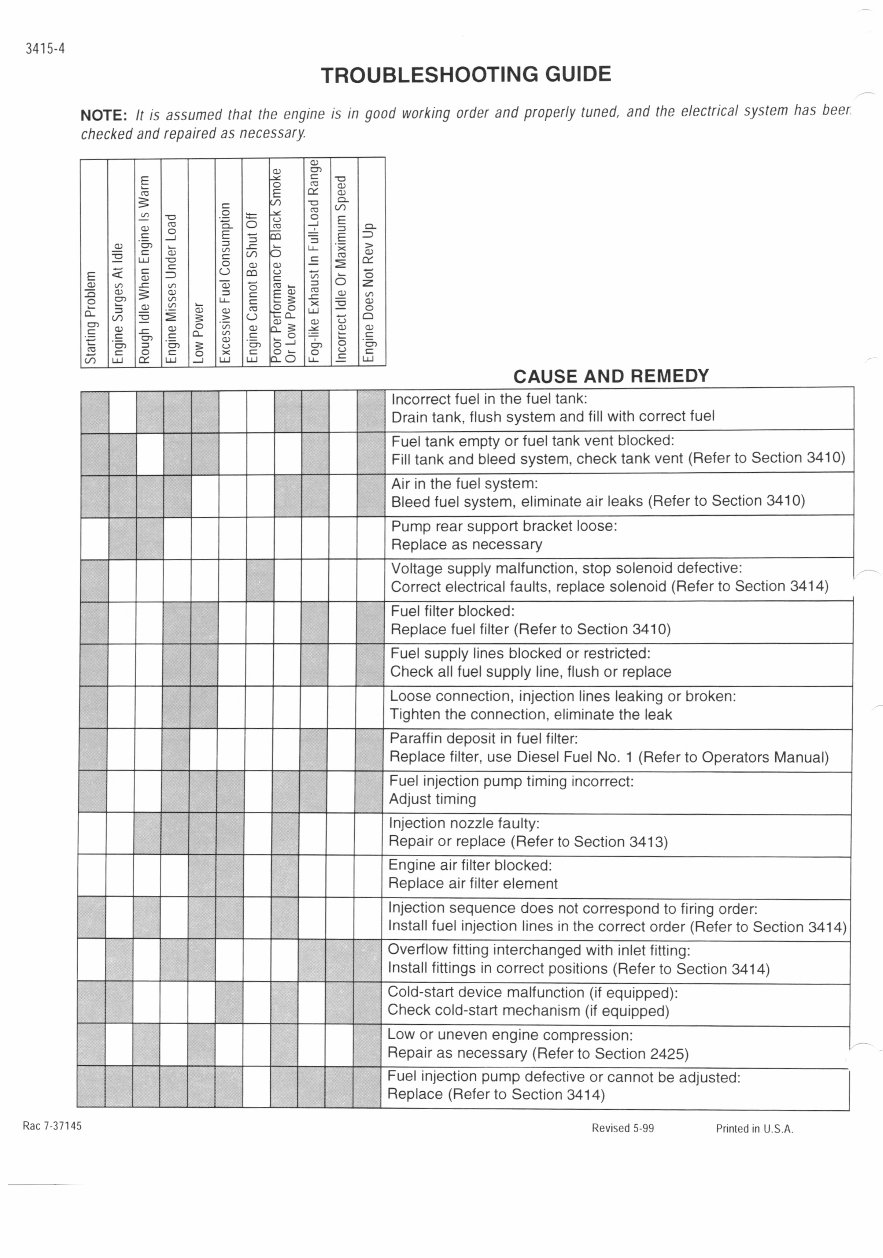
TROUBLESHOOTING GUIDE
NOTE:
It is assumed that the engine is in good working order and properly tuned, and the electrical system has beer
checked and repaired as necessary.
)
C)
0
E
= ' 0
CL
(I)
- D .9
0
CD
CL Ca - 0
E _J E
0 Cn
000
ci) ) CD
E <
C-)
-
0 (1) -= /) CD =
=
CD
0
c °
C > (_) --
D) L) _
- 0
Ln
In
C) CL
0) 0)
0 0 0
__J
=
CM
0 = ) 0
C.)
&)
=
u
C 0
u
0
-
>C
Lu
0
Lu
0
0
0
u .E uj
CAUSE AND REMEDY
- Incorrect fuel in the fuel tank:
Drain tank, flush system and fill with correct fuel
- -
- Fuel tank empty or fuel tank vent blocked:
Fill tank and bleed system, check tank vent (Refer to Section 3410)
Air in the fuel system:
Bleed fuel system, eliminate air leaks (Refer to Section 3410)
- Pump rear support bracket loose:
Replace as necessary
- Voltage supply malfunction, stop solenoid defective:
Correct electrical faults, replace solenoid (Refer to Section 3414)
Fuel filter blocked:
Replace fuel filter (Refer to Section 3410)
Fuel supply lines blocked or restricted:
Check all fuel supply line, flush or replace
Loose connection, injection lines leaking or broken:
Tighten the connection, eliminate the leak
Paraffin deposit in fuel filter:
Replace filter, use Diesel Fuel No. 1 (Refer to Operators Manual)
Fuel injection pump timing incorrect:
Adjust timing
Injection nozzle faulty:
Repair or replace (Refer to Section 3413)
Engine air filter blocked:
- -
Replace air filter element
- Injection sequence does not correspond to firing order:
- -
- Install fuel injection lines in the correct order (Refer to Section 3414)
Overflow fitting interchanged with inlet fitting:
- - -
Install fittings in correct positions (Refer to Section 3414)
- Cold-start device malfunction (if equipped):
Check cold-start mechanism (if equipped)
- Low or uneven engine compression:
Repair as necessary (Refer to Section 2425)
77
Fuel injection pump defective or cannot be adjusted:
- Replace (Refer to Section 3414)
Rac 7-37145
Revised 5-99 Printed in U.S.A.
3..
I
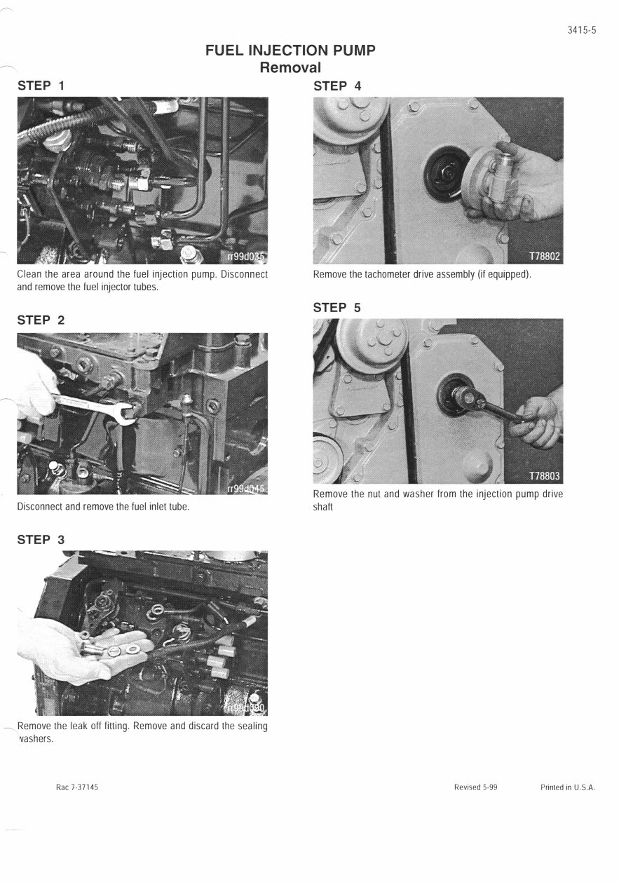
Remove the nut and washer from the injection pump drive
shaft
3415-5
FUEL INJECTION PUMP
Removal
STEP 1 STEP 4
L
Clean the area around the fuel Injection pump. Disconnect
and remove the fuel injector tubes.
STEP 2
Disconnect and remove the fuel inlet tube.
STEP 3
Remove the leak off fitting. Remove and discard the sealing
vashers.
Remove the tachometer drive assembly (it equipped).
STEP 5
Rac 7-37145 Revised 5-99 Printed in U.S.A.
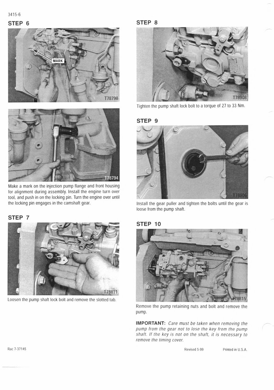
Make a mark on the injection pump flange and front housing
for alignment during assembly. Install the engine turn over
tool, and push in on the locking pin. Turn the engine over until
the locking pin engages in the camshaft gear.
STEP 7
1
I,-
I
-
. T78811
Loosen the pump shaft lock bolt and remove the slotted tab.
Rac 7-37145
STEP 8
J
w/
I1Ti
8
Tighten the pump shaft lock bolt to a torque of 27 to 33 Nm.
STEP 9
Install the gear puller and tighten the bolts until the gear is
loose from the pump shaft.
STEP 10
_J
J1 -
\788 15
Remove the pump retaining nuts and bolt and remove the
pump.
IMPORTANT: Care must be taken when removing the
pump from the gear not to lose the key from the pump
shaft. If the key is not on the shaft, it is necessary to
remove the timing cover.
Revised 5-99 Printed in U.S.A.
3415-7
Installation
STEP 11
VT
STEP 14
I
_ • :V '..
I I
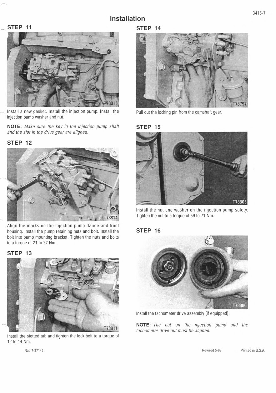
Install a new gasket. Install the injection pump. Install the
injection pump washer and nut.
NOTE: Make sure the key in the injection pump shaft
and the slot in the drive gear are aligned.
STEP 12
\
I
- --
T788 14
Align the marks on the injection pump flange and front
housing. Install the pump retaining nuts and bolt. Install the
bolt into pump mounting bracket. Tighten the nuts and bolts
to a torque of 21 to 27 Nm.
STEP 13
I
178811
k. -
Install the slotted tab and tighten the lock bolt to a torque of
12 to 14 Nm.
Rac 7-37145
I
1
178797
Pull out the locking pin from the camshaft gear.
STEP 15
Install the nut and washer on the injection pump safety.
Tighten the nut to a torque of 59 to 71 Nm.
STEP 16
Install the tachometer drive assembly (it equipped).
NOTE: The nut on the injection pump and the
tachometer drive nut must be aligned.
Revised 5-99 Printed in U.S.A.
3415-8
STEP 17
STEP 19
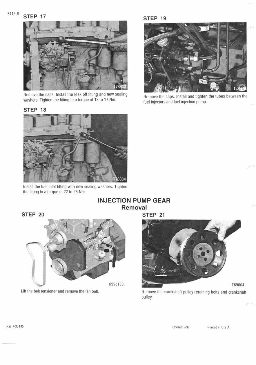
Remove the caps. Install the leak off fitting and new sealing
washers. Tighten the fitting to a torque of 1310 17 Nm.
STEP 18
Remove the caps. Install and tighten the tubes between the
fuel injectors and fuel injection pump.
Install the fuel inlet fitting with new sealing washers. Tighten
the fitting to a torque of 22 to 28 Nm.
INJECTION PUMP GEAR
Removal
STEP 20 STEP 21
ri99cl 33
Lift the belt tensioner and remove the fan belt.
Remove the crankshaft pulley retaining bolts and crankshaft
pulley.
Rac 7-37145
Revised 5-99 Printed in U.S.A.
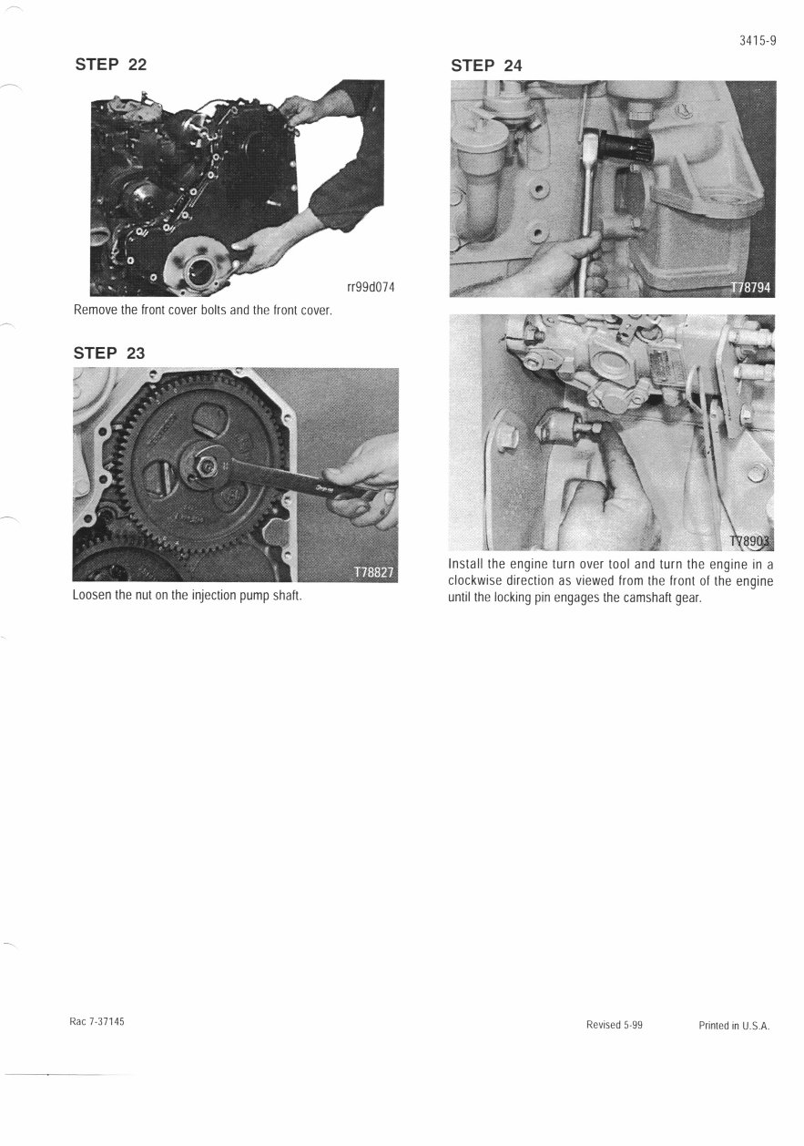
STEP 22
Remove the front cover bolts and the front cover.
STEP 23
Loosen the nut on the injection pump shaft.
3415-9
STEP 24
j
(
Ake
H \ \J
Install the engine turn over tool and turn the engine in a
clockwise direction as viewed from the front of the engine
until the locking pin engages the camshaft gear.
Rac 7.37145
Revised 5-99 Printed in U.S.A.
3415-10
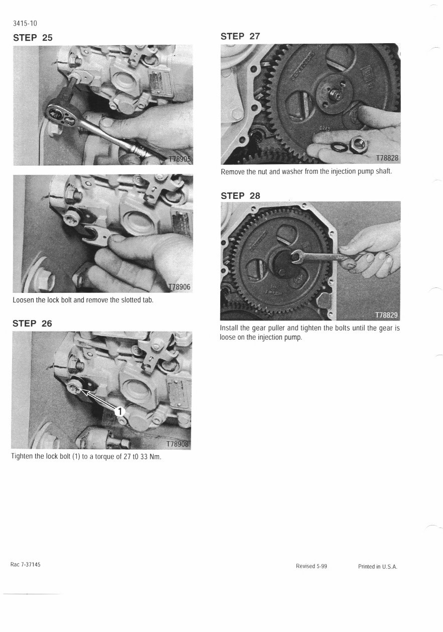
STEP 25
Loosen the lock bolt and remove the slotted tab.
STEP 26
1'
Tighten the lock bolt (1) to a torque of 27 tO 33 Nm,
STEP 27
A111 IItIIII._""'
178828
Remove the nut and washer from the injection pump shaft.
STEP 28
Install the gear puller and tighten the bolts until the gear is
loose on the injection pump.
Rac 7-31145
Revised 5-99 Printed in U.S.A.
You're Reading a Preview
What's Included?
Fast Download Speeds
Online & Offline Access
Access PDF Contents & Bookmarks
Full Search Facility
Print one or all pages of your manual
$30.99
Viewed 60 Times Today


Secure transaction
What's Included?
Fast Download Speeds
Online & Offline Access
Access PDF Contents & Bookmarks
Full Search Facility
Print one or all pages of your manual
$30.99
This manual for Bosch VE Fuel Pump 4-390 Engines includes the following:
- SPECIAL TOOLS
- SPECIAL TORQUES
- VE Injection Pump
- Lock Timing Chart
- TROUBLESHOOTING GUIDE
- FUEL INJECTION PUMP Installation
- INJECTION PUMP GEAR Removal and Installation
- INJECTION PUMP TIMING
- FUEL SHUT - OFF SOLENOID Removal and Disassembly, Assembly and Installation
- PRIMER PUMP Removal and Installation
- TIMING LOCKING PIN
- SPECIAL TOOLS CAS-1690
- Auxiliary Tools
- Torque settings
These manuals are valuable resources for both professional mechanics and DIY enthusiasts.


