Table of Contents 6 Introduction 6 General 6 Why is a governor required with a diesel engine? 8 Speed Droop 8 Functions of the Governor 10 Torque Control 12 Types of Governor 13 Maximum-Speed Governors 13 Minimum-Maximum-Speed Governors 14 Variable-Speed Governors 14 Combination Governors 15 Mechanical Governors 15 Metering Units 16 Minimum-Maximum-Speed Governor RQ 20 Minimum-Maximum-Speed Governor RQU 20 Maximum-Speed Governors RQ and RQU 21 Variable-Speed Governor R QV 24 Variable-Speed Governor RQUV 25 Variable-Speed Governor RQV..K 28 Combination Governors RQV and RQUV 28 Variable-Speed Governor EP/RSV 32 Variable-Speed Governor EPARSUV 33 Minimum-Maximum-Speed Governor EP RS 36 Control-Lever and Control-Rod Stops for Mechanical Governors 36 Control-Lever Stops 36 Spring-Loaded Idle-Speed Stop 36 Reduced-Delivery Stop 37 Control-Rod Stops 37 Rigid Excess-Fuel Stop for Starting 37 Spring-Loaded Control-Rod Stop for RQ Governors 38 Automatic Full-Load Control-Rod Stop 38 Control-Rod Stop with Torque-Control Mechanism 40 Manifold-Pressure Compensator (LIDA) 41 Altitude-Pressure Compensator (ADA) 43 Electric Speed-Control Device 43 Use 43 Design 44 Pneumatic Governor 44 Variable-Speed Governor EP , M.. 44 Operating Principle 45 Operating Characteristics 47 Special Designs 49 Maintenance 50 Testing and Repair 52 Glossary of Technical Terms 55 Test Page
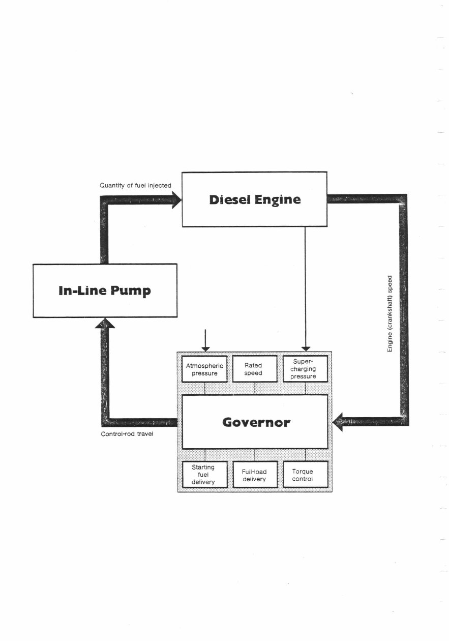
Quantity of fuel injected Diesel Engine In-Line Pump Atmospheric Rated Super- I charging pressure speed pressure Governor Control-rod travel Starting fuel Full-load Torque delivery delivery control
We provided information on in- line pumps for you in the booklet in this series entitled "Diesel Fuel-injection Pumps Types PE and PF". The in-line pump, however, is only one part of the fuel injection system. Equally important is the governor. This device is responsible for ensuring that the engine maintains a certain speed under various load conditions, that the engine speed does not exceed a certain level as protection against self-destruction, and that the engine does not stop during pauses in loaded operation, i.e. during idling. The governor accomplishes all this by controlling the amount of fuel injected into the engine. How the governor performs these as well as a number of other functions is described in this booklet.
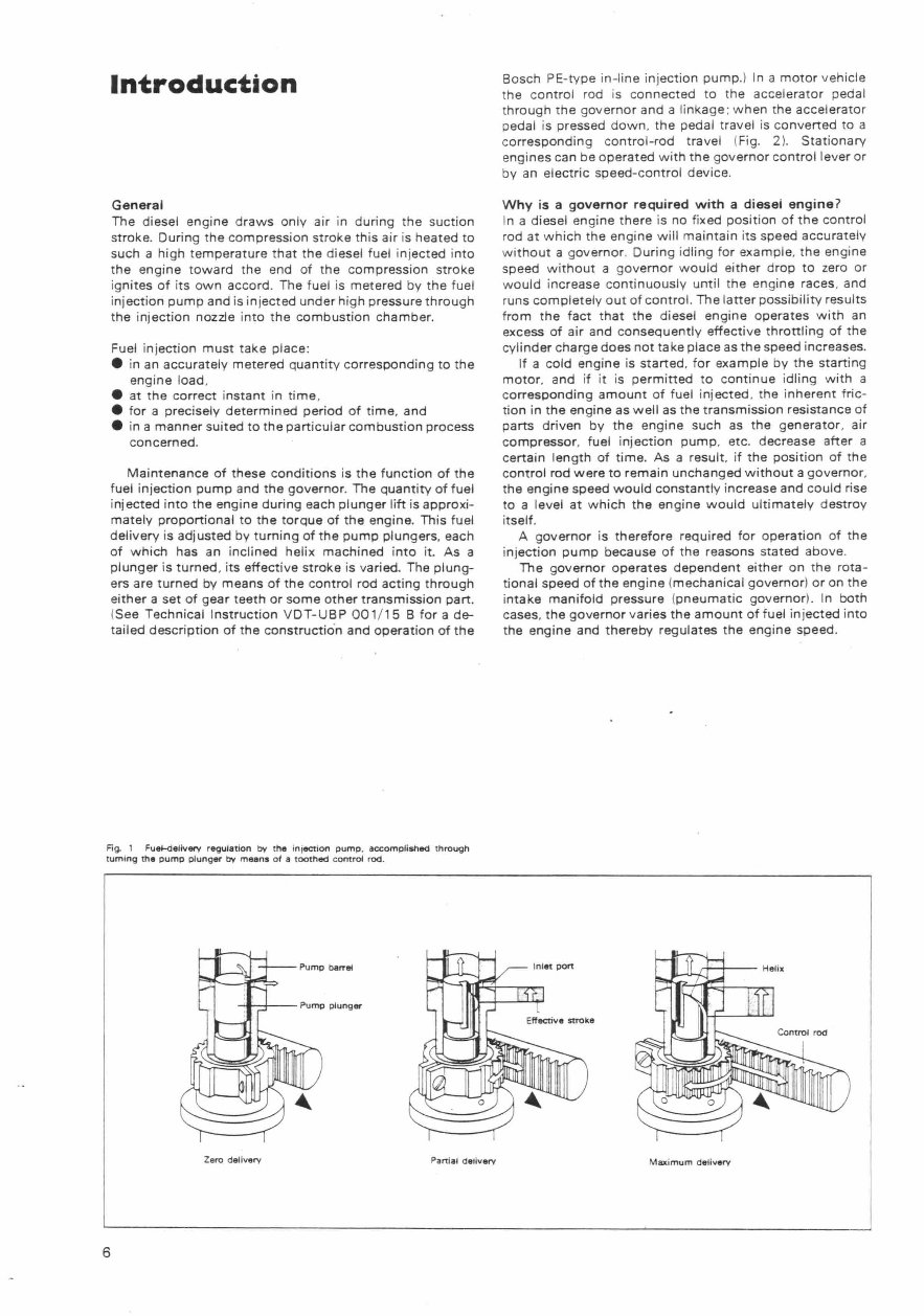
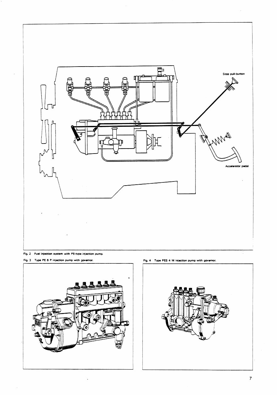
est Irri" Conol MOO 0104, 1 T riH 1 j Introduction General The diesel engine draws only air in during the suction stroke. During the compression stroke this air is heated to such a high temperature that the diesel fuel injected into the engine toward the end of the compression stroke ignites of its own accord. The fuel is metered by the fuel injection pump and is injected under high pressure through the injection nozzle into the combustion chamber. Fuel injection must take place: • in an accurately metered quantity corresponding to the engine load. • at the correct instant in time, • for a precisely determined period of time, and • in a manner suited to the particular combustion process concerned. Maintenance of these conditions is the function of the fuel injection pump and the governor. The quantity of fuel injected into the engine during each plunger lift is approxi- mately proportional to the torque of the engine. This fuel delivery is adjusted by turning of the pump plungers, each of which has an inclined helix machined into it. As a plunger is turned, its effective stroke is varied. The plung- ers are turned by means of the control rod acting through either a set of gear teeth or some other transmission part. (See Technical Instruction VDT-UBP 001/15 B for a de- tailed description of the construction and operation of the Bosch PE-type in-line injection pump.) In a motor vehicle the control rod is connected to the accelerator pedal through the governor and a linkage: when the accelerator pedal is pressed down, the pedal travel is converted to a corresponding control-rod travel (Fig. 2). Stationary engines can be operated with the governor control lever or by an electric speed-control device. Why is a governor required with a diesel engine? In a diesel engine there is no fixed position of the control rod at which the engine will maintain its speed accurately without a governor. During idling for example, the engine speed without a governor would either drop to zero or would increase continuously until the engine races, and runs completely out of control. The latter possibility results from the fact that the diesel engine operates with an excess of air and consequently effective throttling of the cylinder charge does not take place as the speed increases. If a cold engine is started, for example by the starting motor, and if it is permitted to continue idling with a corresponding amount of fuel injected, the inherent fric- tion in the engine as well as the transmission resistance of parts driven by the engine such as the generator, air compressor, fuel injection pump, etc. decrease after a certain length of time. As a result, if the position of the control rod were to remain unchanged without a governor, the engine speed would constantly increase and could rise to a level at which the engine would ultimately destroy itself. A governor is therefore required for operation of the injection pump because of the reasons stated above. The governor operates dependent either on the rota- tional speed of the engine (mechanical governor) or on the intake manifold pressure (pneumatic governor). In both cases, the governor varies the amount of fuel injected into the engine and thereby regulates the engine speed. Fig. 1 Fuel-dellyary regulation by the injection pump, accomplished through turning the pump plunger by means of a toothed control rod. 6
Accelerator pedal Fig. 2 Fuel injection system with PE-type injection pump. Fg_ 3 Type PE 8 P injection pump with governor. 4 Type PES 4 M injection pump with governor. 7
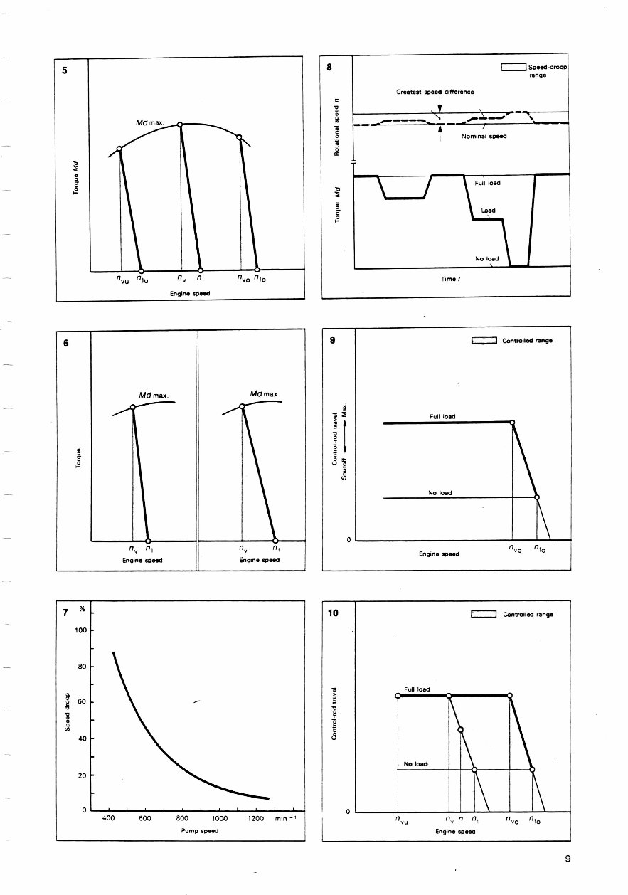
Speed Droop Every engine has a torque characteristic curve correspond- ing to its maximum loading capacity. A certain maximum torque is associated with every speed. If the load on an engine is removed with no change in the position of the control lever, the engine speed may increase within the control range by only a certain permissible amount as determined by the engine manufacturer (for example from n,, =any full-load speed to n i =any idle speed). The in- crease in speed is proportional to the change in load. i.e., the greater the reduction in load, the greater the increase in speed. Conversely of course, when the engine is idling and a load is applied, the speed will decrease somewhat, hence the designation of this characteristic as "speed droop". The speed droop of the governor is generally related to the maximum full-load speed (= rated speed) and is calcu- lated as follows: — nt o — 17, or, in %: o — ni 100%. n, In the above equations, 5 =speed droop n io =high idle speed n,„ =maximum full-load speed Example: (pump speeds) n k, =1000 min (rev/min) n„= 920 min" 1000 — 920 6 — • 100% = 8.7%. 920 As the speed decreases, the speed droop increases, and is at its greatest in the idle-speed range. Generally, more stable behavior of the entire control circuit (governor, engine, and driven machine or vehicle) can be attained by a fairly large speed droop. On the other hand, the speed droop is limited by operating conditions, for example to about 2-5% for generators, .about 6-10% for vehicles and about 10-15% for excavators with a storage flywheel. Fig. 8 shows the effect of the speed droop using a practical example. With the nominal speed set to a constant value, the actual speed varies within the speed-droop range as the load on the engine is changed (resulting, for example, from a change in the slope of the road). Because of these changes in engine speed resulting from changes in load, the speed droop was also known previously as "cyclic irregularity'. Functions of the Governor The basic function of every governor is to limit the high idle speed, i.e., it must ensure that the speed of the diesel engine does not exceed the maximum value specified by the manufacturer. Depending on the type of governor, further functions can be the maintenance of certain speci- fied speeds, e.g. the idle speed, or speeds within a particu- lar rotational-speed range or the entire range between idle speed and high idle (=maximum) speed. 1. Maximum-speed regulation (Fig. 9) When the load is removed from the engine, the maximum full-load speed, n„, may rise no higher than n io (high idle or no-load speed) in accordance with the permissible speed droop. The governor accomplishes this by drawing back the control rod in the shutoff direction. The range n„ —n io is designated the maximum-speed regulation. The greater the speed droop, the greater is the increase in speed from n„ to n 10 . 2. Intermediate-speed regulation (Fig. 10) If required by the intended application of the governor (for example, in vehicles with an auxiliary drive), the governor can also maintain constant, within certain limits, various speeds between the idle and maximum speeds. Depending on the load therefore, the speed n would only fluctuate between n„ (at full load) and ni (with no load placed on the engine) within the performance range of the engine. The following Terms are used in Figs. 5 to 10: =minimum full-load speed n, =any full-load speed =1118XITUT full-load speed =low idle speed "I -.any idle speed =high idle speed Fig. 5 Full-load speed with the corresponding regulated idle speeds Ino-load Weeds). Fig. 6 Increase in speed with 2 different speed droops. Left: small speed droop. right: large speed droop. Fig- 7 Speed droop of an RQV governor at various speeds set by the control lever. Fig. 8 Effect of the speed droop on the actual speed as the engine load is changed. Fig. 9 Control range of a maximum-speed governor. s maximum full-load speed, nk,=idle speed. Fig. 10 Intermediete-speed regulation Ivariable-speed governor). n • minimum full-load speed. 8
z C n v n 1 nvo n lo Engine speed Speed-droop range Greatest speed difference Rota t io nal speed n • Nominal speed Full load No load Time Md max. Md max. n v n i Engine speed a nv fll Engine speed Engine speed nv0 n 10 I - 1 Controlled range Full load No load N 0 10 Control-r od tr av el r- I Controlled range 7 100 80 60 Full load 40 No load 20 0 0 400 600 800 1000 1200 min Pump speed VU n v n t n vo n 10 Engine speed 9
Bosch Technical Instructions In Line Pumps Injection Governors is a comprehensive manual covering various aspects of In Line Pump Governors. It includes an introduction to the topic, general information, and the necessity of a governor with a diesel engine. The manual also delves into speed droop, functions of the governor, torque control, and different types of governors such as maximum-speed governors, minimum-maximum-speed governors, variable-speed governors, and combination governors.
Types of Governors:
Maximum-Speed Governors
Minimum-Maximum-Speed Governors
Variable-Speed Governors
Combination Governors
Mechanical Governors
Furthermore, it provides detailed information on metering units, control-lever and control-rod stops for mechanical governors, manifold-pressure compensator (LIDA), altitude-pressure compensator (ADA), electric speed-control device, and pneumatic governor. The manual also covers the use, design, operating principle, operating characteristics, special designs, maintenance, testing, repair, and a glossary of technical terms. It is a valuable resource for both professional mechanics and DIY enthusiasts.
Recently Viewed
5,521,897Happy Clients
2,594,462eManuals
1,120,453Trusted Sellers
15Years in Business
Price:
Actual Price:
Bosch Technical instructions In Line pumps Injection Govern