

2012 MANITOU FORK Service Manual
What's Included?
Fast Download Speeds
Online & Offline Access
Access PDF Contents & Bookmarks
Full Search Facility
Print one or all pages of your manual
2012
1 2012 SERVICE MANUAL
Hayes Performance Systems
5800 W. Donges Bay Rd.
Mequon, WI 53092
Tel: 888.686.3472
Email: techsupport@hayesbicycle.com
Web: www.hayescomponents.com
Hayes Components Europe
Dirnismaning 20 a
85748 Garching (b. Munich)
Germany
ph: +49 (0)89 203237450
Email: techsupportEU@hayesbicycle.com
Web: www.hayescomponents.com
2
2012 SERVICE MANUAL
This manual is intended to guide the user through the steps necessary to fully service and maintain
the Maitou suspension forks.
Suspension forks by design can contain preloaded springs, gases and fluids under
extreme pressures. Warnings contained in this manual must be observed to avoid damage to fork,
serious injury or even death.
We highly recommend that service to this fork be performed by a certified bi-
cycle mechanic. Failure to follow instructions presented in this manual could lead to serious injury
or death. Any questions about the servicing of this fork or the manual itself should be directed to
Manitou Customer Support at:
Phone: 888-686-3472
Email: techsupport@hayesbicycle.com
INTRODUCTION

3 2012 SERVICE MANUAL
This manual is divided up into different sections, each one pertaining to a different part of the
servicing of your fork. Below is a list of our fork models and which sections you will use to service
your particular fork.
Circus Comp/Match/Tower Comp Forks
1. Section 1 – Casting Removal
2. Section 3 – Dust Seal Replacement
3. Section 4 – Coil Spring Service
4. Section 8 – Absolute+ Service
5. Section 10 – Casting Installation
Circus Expert/Minute Expert/Tower Expert
Forks
1. Section 1 – Casting Removal
2. Section 3 – Dust Seal Replacement
3. Section 7 – ACT Air Service
4. Section 8 – Absolute+ Service
5. Section 10 – Casting Installation
R7 MRD Forks
1. Section 2 – MRD Casting Removal
2. Section 3 – Dust Seal Replacement
3. Section 6 – TS Air Service
4. Section 9 – Absolute+ MRD Service
5. Section 11 – MRD Casting Installation
Marvel Pro Forks
1. Section 2 – MRD Casting Removal
2. Section 3 – Dust Seal Replacement
3. Section 8 – ISO Air Service
4. Section 9 – Absolute+ MRD Service
5. Section 11 – MRD Casting Installation
Minute Pro/Tower Pro Forks
1. Section 1 – Casting Removal
2. Section 3 – Dust Seal Replacement
3. Section 5 – MARS Air Spring Service
4. Section 8 - Absolute+ Service
5. Section 10 – Casting Installation
R7 Forks
1. Section 1 – Casting Removal
2. Section 3 – Dust Seal Replacement
3. Section 6 – TS Air Service
4. Section 8 – Absolute+ Service
5. Section 10 - Casting Installation
Marvel Expert Forks
1. Section 1 – Casting Removal
2. Section 3 – Dust Seal Replacement
3. Section 8 – ISO Air Service
4. Section 8 – Absolute+ Service
5. Section 10 – Casting Installation
Fork models
4
2012 SERVICE MANUAL
Section 1 - Casting Removal 4
Section 2 - MRD Casting Removal 5
Section 3 - Dust Seal Replacement 6
Section 4 - Coil Spring Service 7 - 8
Section 5 - MARS Air Spring Service 9 - 10
Section 6 - TS Air Spring Service 11 - 12
Section 7 - ACT Air Spring Service 13 - 14
Section 8 - ISO Air Spring Service 15 - 16
Section 9 - Absolute+ Service 17 - 18
Section 10 - Absolute+ MRD Service 19 - 20
Section 11 - Casting Installation 21
Section 12 - MRD Casting Installation 22
Oil Height Chart 23
Fork Exploded Diagrams 24 - 34
table of contents
PAGE NUMBER SECTION
5 2012 SERVICE MANUAL
FIG. 1
FIG. 2
FIG. 3
casting removal
1
2
3
4
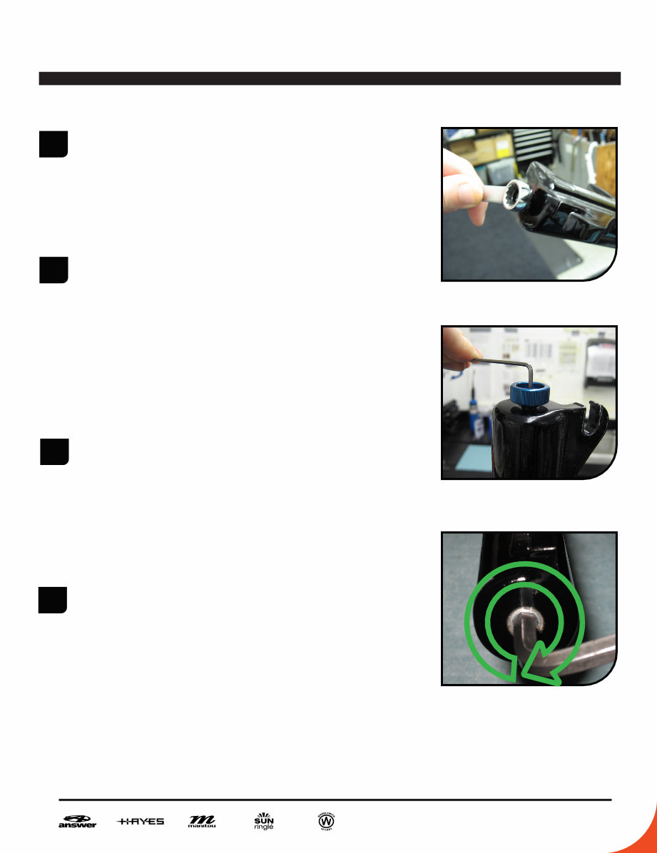
From the left leg dropout (Left when sitting on
the bike), use a 10 or 11mm wrench to remove
the compression rod screw. (Fig. 1)
From the right leg dropout, if the fork has ad-
justable rebound, the knob will need to be re-
moved. Screw the rebound all the way in (clock-
wise) remove the 2mm hex screw inside the
knob by turning it counter clockwise. Remove
the knob by pulling gently away from the fork.
(Fig. 2)
Use an 8mm hex wrench to turn the damper
clockwise until it can be pushed into the casting.
(Fig. 3)
4. Remove crown/steer/inner leg assembly from
the outer leg casting by pulling firmly on the
casting. If the fork uses the Semi bath Lubri-
cation system, use caution as the oil that is in
the casting will be released when the casting is
removed, it is best to do this over some type of
catch pan.
6
2012 SERVICE MANUAL
mrd casting removal
FIG. 1
FIG. 2
FIG. 3
FIG. 4
1
2
3
4
5
6
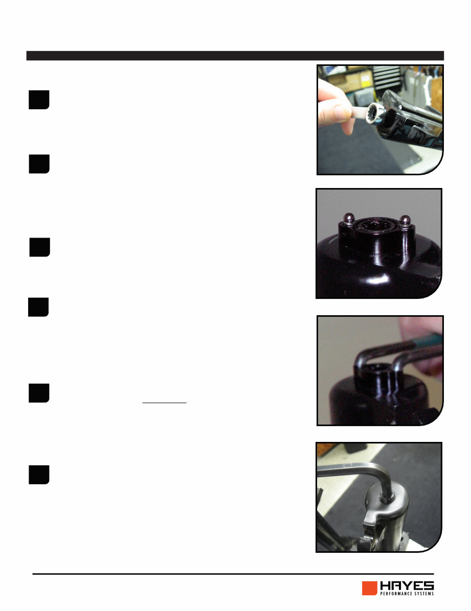
From the left leg dropout (Left when sitting on
the bike), use a 10 or 11mm wrench to remove
the compression rod screw. (Fig. 1)
Remove the blue rebound knob on the bottom of
the right leg with a 1.5mm Allen wrench. Be cau-
tious of the detent balls and springs under the
knob as they are very small and easily lost.
Remove the detent balls and springs from the De-
tent Housing. (Fig. 2)
Remove the Detent housing by unscrewing it
counter-clockwise using a green Park Tool pin
spanner (or similar tool) inserted into the holes
that the springs and detent balls sit in. (Fig. 3)
Using a 7mm or 8mm Allen wrench, turn the re-
bound assembly clockwise until it can be pushed
into the casting. (Fig. 4)
Remove crown/steer/inner leg assembly from the
outer leg casting by pulling firmly on the casting.
The fork uses the Semi bath Lubrication system,
use caution as the oil that is in the casting will be
released when the casting is removed, it is best
to do this over some type of catch pan.

7 2012 SERVICE MANUAL
dust seal replacement
FIG. 1
FIG. 2
FIG. 3
FIG. 4
1
2
3
4
5
Before replacing the dust seals you will need to
remove the lower casting. Refer to the Casting
Removal or MRD Casting Removal instructions
depending on which model fork you have.
To remove the dust seals, first remove the seal
tension springs (otherwise they will get dam-
aged), then take a large flat-bladed screwdriver
and insert the tip between the bottom of the seal
and the top of the foam wiper. (Fig. 1)
Push down on the screwdriver. This will pop the
seal out of the casting. Next remove the foam oil
ring. (Fig. 2)
Oil the foam rings (new or after cleaning the old
rings) with a small amount of semi-bath oil and
place them in the top of the casting above the
Upper Bushings. (Fig. 3)
Install the dust seal into the leg, use a large sock-
et or piece of round tubing that is large enough
in diameter to press on the outside shoulder of
the seal rather than putting pressure on the seal-
ing lip and spring so that they are not damaged.
(Fig. 4) Repeat steps 1-4 for the opposite casting
leg.
8
2012 SERVICE MANUAL
coil spring service
FIG. 1
FIG. 2
FIG. 3
FIG. 4
1
2
3
4
5
9
6
10
11
12
13
7
8
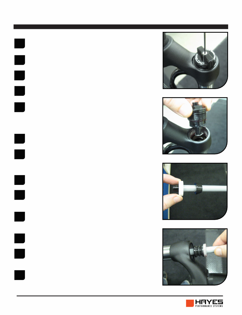
Using a 2mm Allen wrench, remove the knob from
the preload adjuster. (Fig. 1)
Remove the preload adjuster from the fork using a
20mm socket. (Fig. 2)
Pull the coil spring out of the stanchion leg.
Remove travel spacer and bottom out bumper from
the end of the compression rod assembly. (Fig. 3)
Remove the compression rod assembly from the
stanchion leg. The compression rod comes out from
the top of the stanchion leg. Turn the fork sideways
or upside down to get the compression rod out of
the leg. (Fig. 4)
Inspect compression rod and top-out bumper. If
damaged replace.
Install compression rod assembly into the stan-
chion leg. Insert through the top of the stanchion
leg and maneuver the rod until it drops through the
hole at the bottom of the stanchion leg.
Lightly grease the spring and install into stanchion
leg.
Install the preload adjuster into the fork leg. Tight-
en down using a 20mm socket to 5,1- 6,2 Nm (45-
55 in. lbs).
Using a 2mm Allen wrench, install the preload knob
onto the adjuster. Tighten knob down to 0,5-0,7
Nm (4-6 in. lbs).
Install bottom-out bumper and travel spacer onto
the end of the compression rod.
The casting needs to be removed prior to servicing
the coil spring. Refer to the Casting Removal In-
structions first.
Turn the preload knob counter-clockwise until it
stops to relieve the preload on the spring.
9 2012 SERVICE MANUAL
circus comp travel change
FIG. 1
FIG. 2
1
2
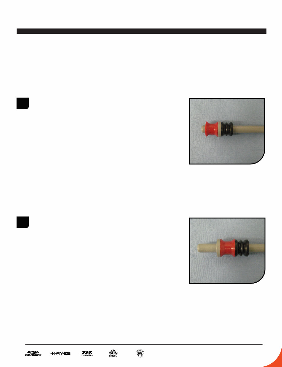
TRAVEL CONVERSION ON MATCH AND CIRCUS COMP
80/100MM FORKS
The Match/Circus Comp 80 and 100mm forks can
be converted to either travel by moving a spacer
on the compression rod. Follow steps 1-7 to re-
move the compression rod form the fork.
The travel of the fork is determined by a plastic
spacer. The spacer being on top of the flange on
the compression rod will cause the fork to have
100mm of travel. (Fig. 1). The spacer being on
the bottom on the flange will cause the fork to
have 80mm of travel. (Fig. 2)
100
80
You're Reading a Preview
What's Included?
Fast Download Speeds
Online & Offline Access
Access PDF Contents & Bookmarks
Full Search Facility
Print one or all pages of your manual
$36.99
Viewed 79 Times Today


Secure transaction
What's Included?
Fast Download Speeds
Online & Offline Access
Access PDF Contents & Bookmarks
Full Search Facility
Print one or all pages of your manual
$36.99
These digital manuals provide comprehensive instructions for maintaining and repairing various types of forks used in different models. Whether you are a professional mechanic or a DIY enthusiast, these manuals offer valuable insights into the inner workings of the following fork types:
- Circus Comp/Match/Tower Comp Forks
- Section 1: Casting Removal
- Section 3: Dust Seal Replacement
- Section 4: Coil Spring Service
- Section 8: Absolute+ Service
- Section 10: Casting Installation
- Circus Expert/Minute Expert/Tower Expert Forks
- Section 1: Casting Removal
- Section 3: Dust Seal Replacement
- Section 7: ACT Air Service
- Section 8: Absolute+ Service
- Section 10: Casting Installation
- R7 MRD Forks
- Section 2: MRD Casting Removal
- Section 3: Dust Seal Replacement
- Section 6: TS Air Service
- Section 9: Absolute+ MRD Service
- Section 11: MRD Casting Installation
- Marvel Pro Forks
- Section 2: MRD Casting Removal
- Section 3: Dust Seal Replacement
- Section 8: ISO Air Service
- Section 9: Absolute+ MRD Service
- Section 11: MRD Casting Installation
- Minute Pro/Tower Pro Forks
- Section 1: Casting Removal
- Section 3: Dust Seal Replacement
- Section 5: MARS Air Spring Service
- Section 8: Absolute+ Service
- Section 10: Casting Installation
- R7 Forks
- Section 1: Casting Removal
- Section 3: Dust Seal Replacement
- Section 6: TS Air Service
- Section 8: Absolute+ Service
- Section 10: Casting Installation
- Marvel Expert Forks
- Section 1: Casting Removal
- Section 3: Dust Seal Replacement
- Section 8: ISO Air Service
- Section 8: Absolute+ Service
- Section 10: Casting Installation
These manuals are an indispensable resource for anyone seeking to understand and maintain the intricate components of these forks.


