


GENERAL INFORMATION 1-1
SECTION 1
GENERAL INFORMATION
INDEX
Subject Page
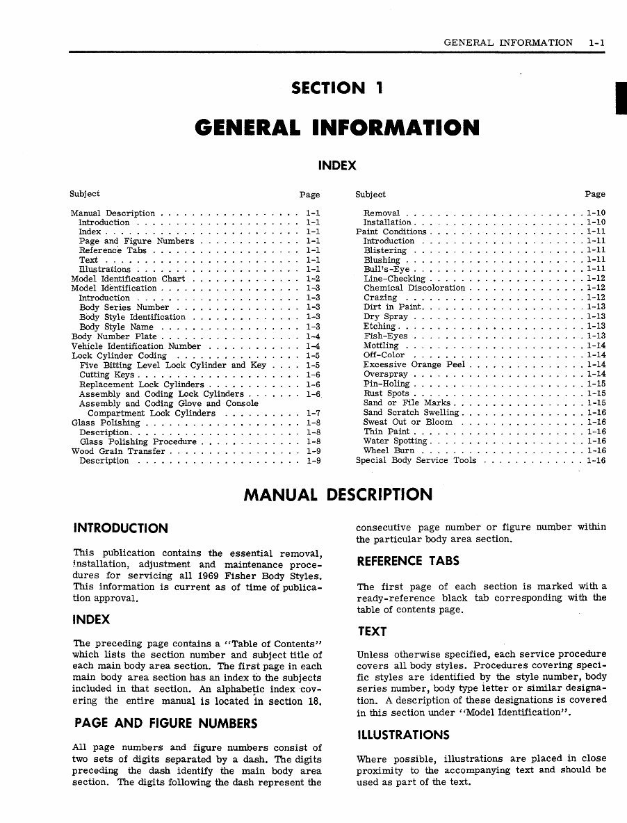
Manual Description 1-1
Introduction 1-1
Index 1-1
Page and Figure Numbers 1-1
Reference Tabs 1-1
Text 1-1
Illustrations 1-1
Model Identification Chart 1-2
Model Identification 1-3
Introduction 1-3
Body Series Number 1-3
Body Style Identification 1-3
Body Style Name 1-3
Body Number Plate 1-4
Vehicle Identification Number 1-4
Lock Cylinder Coding 1-5
Five Bitting Level Lock Cylinder and Key .... 1-5
Cutting Keys 1-6
Replacement Lock Cylinders 1-6
Assembly and Coding Lock Cylinders 1-6
Assembly and Coding Glove and Console
Compartment Lock Cylinders 1-7
Glass Polishing 1-8
Description 1-8
Glass Polishing Procedure 1-8
Wood Grain Transfer 1-9
Description 1-9
Subject Page
Removal 1-10
Installation 1-10
Paint Conditions 1-11
Introduction 1-11
Blistering 1-11
Blushing 1-11
Bull's-Eye 1-11
Line-Checking 1-12
Chemical Discoloration 1-12
Crazing 1-12
Dirt in Paint 1-13
Dry Spray 1-13
Etching 1-13
Fish-Eyes 1-13
Mottling 1-14
Off-Color 1-14
Excessive Orange Peel 1-14
Overspray 1-14
Pin-Holing 1-15
Rust Spots 1-15
Sand or File Marks 1-15
Sand Scratch Swelling 1-16
Sweat Out or Bloom 1-16
Thin Paint 1-16
Water Spotting 1-16
Wheel Burn 1-16
Special Body Service Tools 1-16
MANUAL DESCRIPTION
INTRODUCTION
This publication contains the essential removal,
installation, adjustment and maintenance proce-
dures for servicing all 1969 Fisher Body Styles.
This information is current as of time of publica-
tion approval.
INDEX
The preceding page contains a "Table of Contents"
which lists the section number and subject title of
each main body area section. The first page in each
main body area section has an index to the subjects
included in that section. An alphabetic index cov-
ering the entire manual is located in section 18.
PAGE AND FIGURE NUMBERS
All page numbers and figure numbers consist of
two sets of digits separated by a dash. The digits
preceding the dash identify the main body area
section. The digits following the dash represent the
consecutive page number or figure number within
the particular body area section.
REFERENCE TABS
The first page of each section is marked with a
ready-reference black tab corresponding with the
table of contents page.
TEXT
Unless otherwise specified, each service procedure
covers all body styles. Procedures covering speci-
fic styles are identified by the style number, body
series number, body type letter or similar designa-
tion. A description of these designations is covered
in this section under ''Model Identification".
ILLUSTRATIONS
Where possible, illustrations are placed in close
proximity to the accompanying text and should be
used as part of the text.
1-2 GENERAL INFORMATION
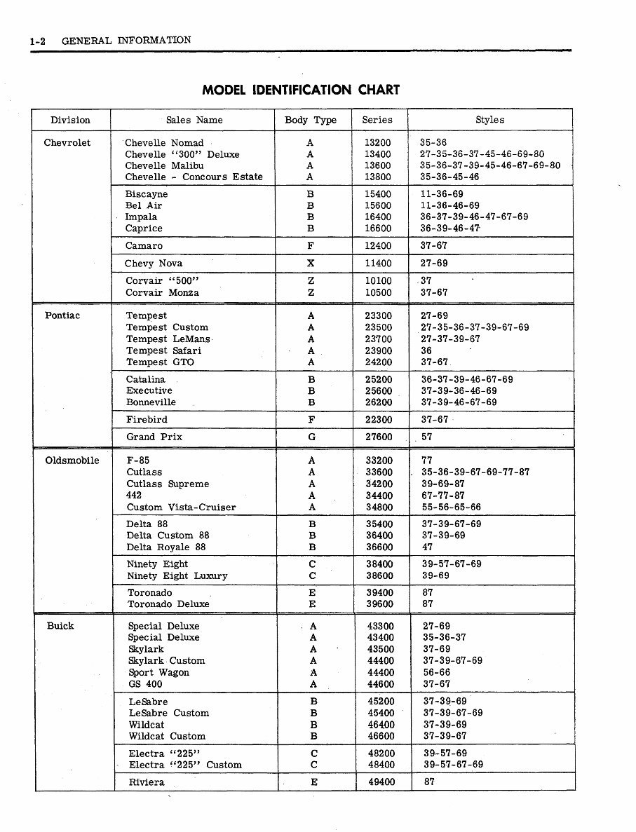
MODEL IDENTIFICATION CHART
Division
Chevrolet
Pontiac
Oldsmobile
Buick
Sales Name
Chevelle Nomad
Chevelle "300" Deluxe
Chevelle Malibu
Chevelle - Concours Estate
Biscayne
Bel Air
Impala
Caprice
Camaro
Chevy Nova
Corvair "500"
Corvair Monza
Tempest
Tempest Custom
Tempest LeMans
Tempest Safari
Tempest GTO
Catalina
Executive
Bonneville
Firebird
Grand Prix
F-85
Cutlass
Cutlass Supreme
442
Custom Vista-Cruiser
Delta 88
Delta Custom 88
Delta Royale 88
Ninety Eight
Ninety Eight Luxury
Toronado
Toronado Deluxe
Special Deluxe
Special Deluxe
Skylark
Skylark Custom
Sport Wagon
GS 400
LeSabre
LeSabre Custom
Wildcat
Wildcat Custom
Electra "225"
Electra "225" Custom
Riviera
Body Type
A
A
A
A
B
B
B
B
F
X
Z
z
A
A
A
A
A
B
B
B
F
G
A
A
A
A
A
B
B
B
C
C
E
E
• A
A
A
A
A
A
B
B
B
B
C
C
E
Series
13200
13400
13600
13800
15400
15600
16400
16600
12400
11400
10100
10500
23300
23500
23700
23900
24200
25200
25600
26200
22300
27600
33200
33600
34200
34400
34800
35400
36400
36600
38400
38600
39400
39600
43300
43400
43500
44400
44400
44600
45200
45400
46400
46600
48200
48400
49400
Styles
35-36
27-35-36-37-45-46-69-80
35-36-37-39-45-46-67-69-80
35-36-45-46
11-36-69
11-36-46-69
36-37-39-46-47-67-69
36-39-46-47-
37-67
27-69
37
37-67
27-69
27-35-36-37-39-67-69
27-37-39-67
36
37-67
36-37-39-46-67-69
37-39-36-46-69
37-39-46-67-69
37-67
. 57
77
. 35-36-39-67-69-77-87
39-69-87
67-77-87
55-56-65-66
37-39-67-69
37-39-69
47
39-57-67-69
39-69
87
87
27-69
35-36-37
37-69
37-39-67-69
56-66
37-67
37-39-69
37-39-67-69
37-39-69
37-39-67
39-57-69
39-57-67-69
87
GENERAL INFORMATION 1-3
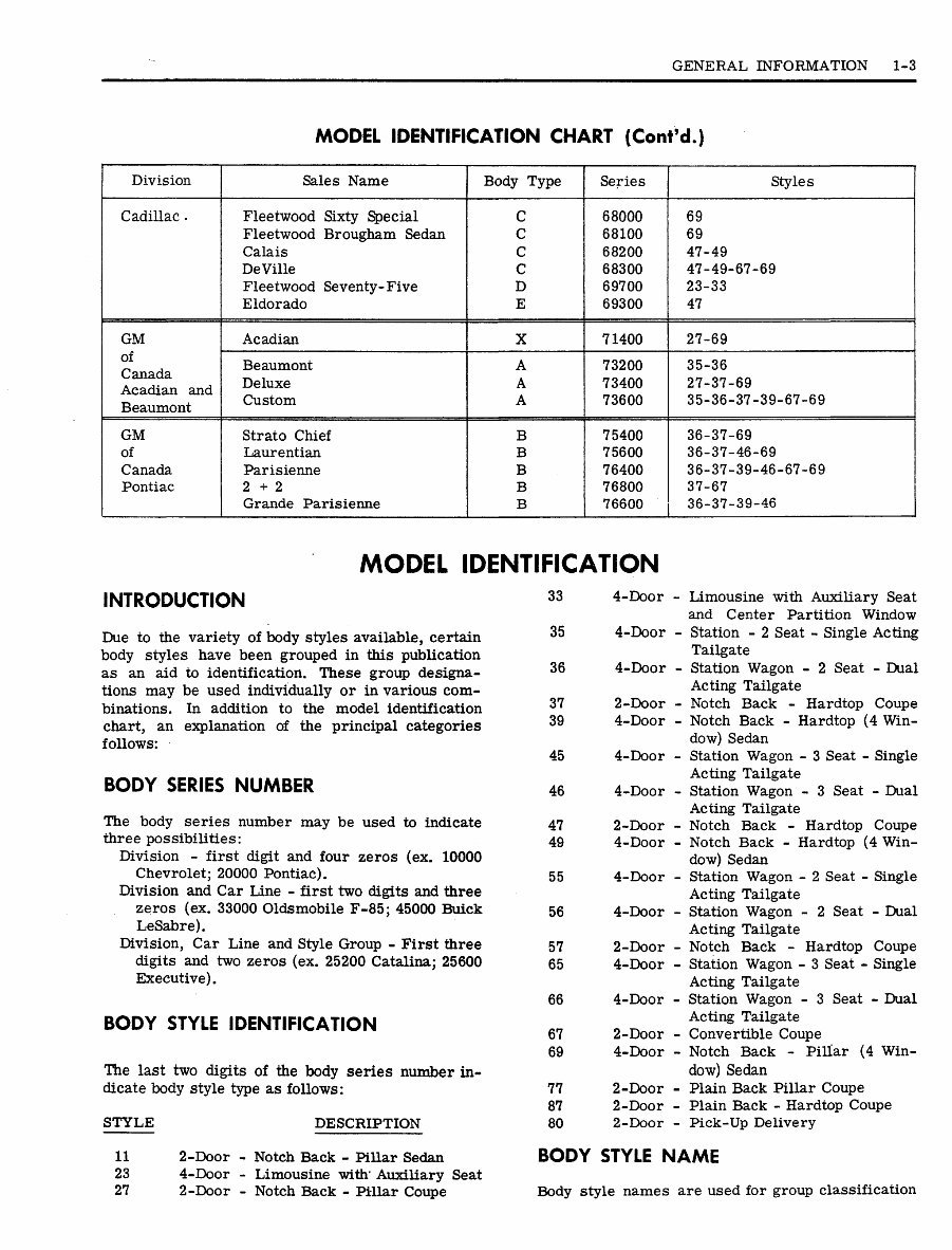
MODEL IDENTIFICATION CHART (Cont'd.)
Division
Cadillac -
GM
of
Canada
Acadian and
Beaumont
GM
of
Canada
Pontiac
Sales Name
Fleetwood Sixty Special
Fleetwood Brougham Sedan
Calais
DeVille
Fleetwood Seventy-Five
Eldorado
Acadian
Beaumont
Deluxe
Custom
Strato Chief
Laurentian
Parisienne
2+2
Grande Parisienne
Body Type
C
C
C
C
D
E
X
A
A
A
B
B
B
B
B
Series
68000
68100
68200
68300
69700
69300
71400
73200
73400
73600
75400
75600
76400
76800
76600
Styles
69
69
47-49
47-49-67-69
23-33
47
27-69
35-36
27-37-69
35-36-37-39-67-69
36-37-69
36-37-46-69
36-37-39-46-67-69
37-67
36-37-39-46
INTRODUCTION
MODEL IDENTIFICATION
33 4-Door
Due to the variety of body styles available, certain
body styles have been grouped in this publication
as an aid to identification. These group designa-
tions may be used individually or in various com-
binations. In addition to the model identification
chart, an explanation of the principal categories
follows:
BODY SERIES NUMBER
The body series number may be used to indicate
three possibilities:
Division - first digit and four zeros (ex. 10000
Chevrolet; 20000 Pontiac).
Division and Car Line - first two digits and three
zeros (ex. 33000 Oldsmobile F-85; 45000 Buick
LeSabre).
Division, Car Line and Style Group - First three
digits and two zeros (ex. 25200 Catalina; 25600
Executive).
BODY STYLE IDENTIFICATION
The last two digits of the body series number in-
dicate body style type as follows:
STYLE DESCRIPTION
11 2-Door - Notch Back - Pillar Sedan
23 4-Door - Limousine with
1
Auxiliary Seat
27 2-Door - Notch Back - Pillar Coupe
- Limousine with Auxiliary Seat
and Center Partition Window
- Station - 2 Seat - Single Acting
Tailgate
- Station Wagon - 2 Seat - Dual
Acting Tailgate
- Notch Back - Hardtop Coupe
- Notch Back - Hardtop (4 Win-
dow) Sedan
- Station Wagon - 3 Seat - Single
Acting Tailgate
- Station Wagon - 3 Seat - Dual
Acting Tailgate
- Notch Back - Hardtop Coupe
- Notch Back - Hardtop (4 Win-
dow) Sedan
- Station Wagon - 2 Seat - Single
Acting Tailgate
- Station Wagon - 2 Seat - Dual
Acting Tailgate
- Notch Back - Hardtop Coupe
- Station Wagon - 3 Seat - Single
Acting Tailgate
- Station Wagon - 3 Seat - Dual
Acting Tailgate
- Convertible Coupe
- Notch Back - Pillar (4 Win-
dow) Sedan
- Plain Back Pillar Coupe
- Plain Back - Hardtop Coupe
- Pick-Up Delivery
BODY STYLE NAME
Body style names are used for group classification
35
36
37
39
45
46
47
49
55
56
57
65
66
67
69
77
87
80
4-Door
4-Door
2-Door
4-Door
4-Door
4-Door
2-Door
4-Door
4-Door
4-Door
2-Door
4-Door
4-Door
2-Door
4-Door
2-Door
2-Door
2-Door
1-4 GENERAL INFORMATION
as follows (style numbers suffix shown in brackets):
Closed Style
Two-door sedan (11)
Two-door coupe (27,77)
Four-door sedan (69)
Limousine (23,33)
Hardtop
Sport coupe hardtop (37, 47, 57, 87)
Sedan hardtop (39, 49)
Station Wagon
Station wagon two seat (35-36, less skylight;
55-56 with skylight)
Station wagon three seat (45-46 less skylight;
65-66 with skylight)
Convertible Coupe (67)
Sedan Delivery (80)
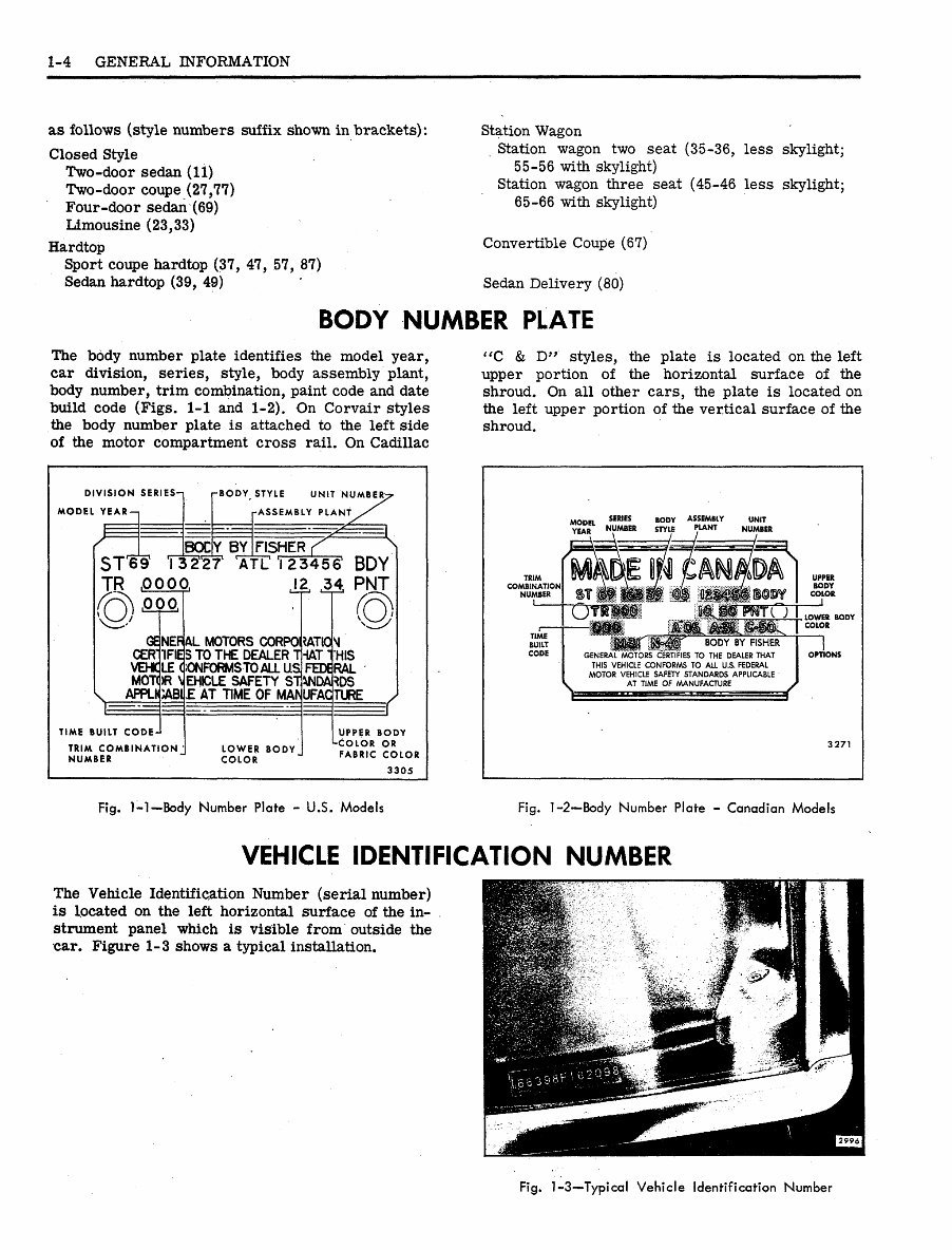
BODY NUMBER PLATE
The body number plate identifies the model year,
car division, series, style, body assembly plant,
body number, trim combination, paint code and date
build code (Figs. 1-1 and 1-2). On Corvair styles
the body number plate is attached to the left side
of the motor compartment cross rail. On Cadillac
"C & D" styles, the plate is located on the left
upper portion of the horizontal surface of the
shroud. On all other cars, the plate is located on
the left upper portion of the vertical surface of the
shroud.
DIVISION SERIES-i
MODEL YEAR
ST
TR
i
-BODY STYLE UNIT NUMBEI
ASSEMBLY PLANT
BOC|Y BY | FISHER
I 32"2T T l T
,0000,
•000,
TIME BUILT CODE-J
TRIM COMBINATION
NUMBER
123456' BDY
J2, £$ PNJ
THAT
GENEPAL MOTORS CORPORATION
CERTIFIES TO THE DEALER
VEHC LE OONFORMSTOALL US
MOTOR VEHICLE SAFETY STWDAttDS
APPLI<|;ABI|£ AT TIME OF M M UFACTURE
LOWER BODY
COLOR
HIS
FEDERAL
UPPER BODY
-COLOR OR
FABRIC COLOR
3305
MODEL MIIMB . D
YEAR NUMBER
TRIM
COMBINATION
NUMBER
THIS VEHICLE CONFORMS TO ALL U.S. FEDERAL
MOTOR VEHICLE SAFETY STANDARDS APPLICABLE
AT TIME OF MANUFACTURE
3271
Fig. 1-1-Body Number Plate - U.S. Models Fig. 1-2—Body Number Plate - Canadian Models
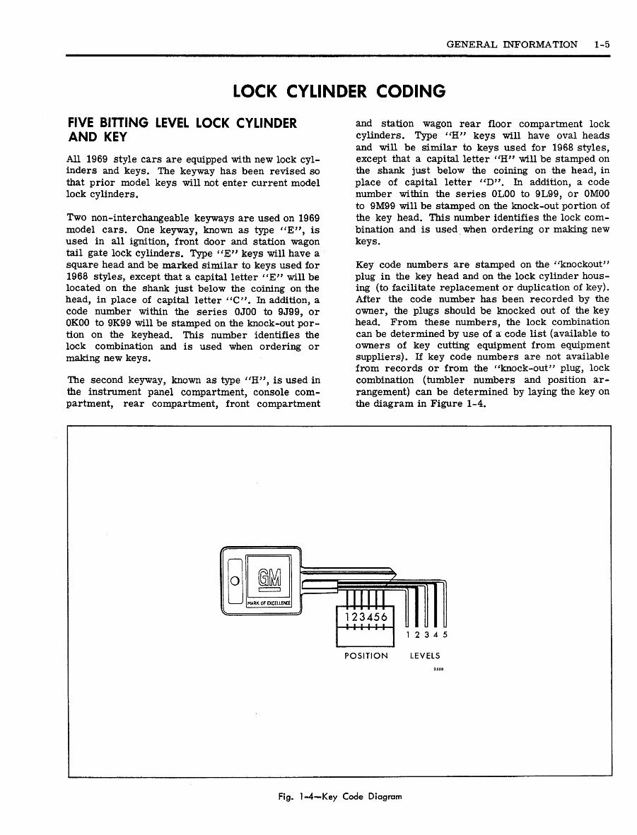
VEHICLE IDENTIFICATION NUMBER
The Vehicle Identification Number (serial number)
is located on the left horizontal surface of the in-
strument panel which is visible from outside the
car. Figure 1-3 shows a typical installation.
Fig. 1-3—Typical Vehicle Identification Number
GENERAL INFORMATION 1-5
LOCK CYLINDER CODING
FIVE BITTING LEVEL LOCK CYLINDER
AND KEY
All 1969 style cars are equipped with new lock cyl-
inders and keys. The keyway has been revised so
that prior model keys will not enter current model
lock cylinders.
Two non-interchangeable keyways are used on 1969
model cars. One keyway, known as type "E", is
used in all ignition, front door and station wagon
tail gate lock cylinders. Type " E " keys will have a
square head and be marked similar to keys used for
1968 styles, except that a capital letter "E" will be
located on the shank just below the coining on the
head, in place of capital letter "C". In addition, a
code number within the series 0J00 to 9J99, or
0K00 to 9K99 will be stamped on the knock-out por-
tion on the keyhead. This number identifies the
lock combination and is used when ordering or
making new keys.
The second keyway, known as type "H", is used in
the instrument panel compartment, console com-
partment, rear compartment, front compartment
and station wagon rear floor compartment lock
cylinders. Type "H" keys will have oval heads
and will be similar to keys used for 1968 styles,
except that a capital letter "H" will be stamped on
the shank just below the coining on the head, in
place of capital letter "D'\ In addition, a code
number within the series 0L00 to 9L99, or 0M00
to 9M99 will be stamped on the knock-out portion of
the key head. This number identifies the lock com-
bination and is used when ordering or making new
keys.
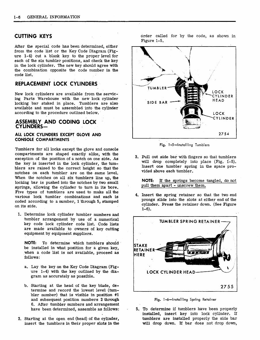
Key code numbers are stamped on the "knockout"
plug in the key head and on the lock cylinder hous-
ing (to facilitate replacement or duplication of key).
After the code number has been recorded by the
owner, the plugs should be knocked out of the key
head. From these numbers, the lock combination
can be determined by use of a code list (available to
owners of key cutting equipment from equipment
suppliers). If key code numbers are not available
from records or from the "knock-out" plug, lock
combination (tumbler numbers and position ar-
rangement) can be determined by laying the key on
the diagram in Figure 1-4.
>4ARK OF EXCELLENCE
1 2 3 4 5
POSITION LEVELS
Fig. 1-4—Key Code Diagram
1-6 GENERAL INFORMATION
CUTTING KEYS
After the special code has been determined, either
from the code list or the Key Code Diagram (Fig-
ure 1-4) cut a blank key to the proper level for
each of the six tumbler positions, and check the key
in the lock cylinder. The new key should agree with
the combination opposite the code number in the
code list.
REPLACEMENT LOCK CYLINDERS
New lock cylinders are available from the servic-
ing Parts Warehouse with the new lock cylinder
locking bar staked in place. Tumblers are also
available and must be assembled into the cylinder
according to the procedure outlined below.
ASSEMBLY AND CODING LOCK
CYLINDERS-
ALL LOCK CYLINDERS EXCEPT GLOVE AND
CONSOLE COMPARTMENTS
Tumblers for all locks except the glove and console
compartments are shaped exactly alike, with the
exception of the position of a notch on one side. As
the key is inserted in the lock cylinder, the tum-
blers are raised to the correct height so that the
notches on each tumbler are on the same level.
When the notches on all six tumblers line up, the
locking bar is pushed into the notches by two small
springs, allowing the cylinder to turn in its bore.
Five types of tumblers are used to make all the
various lock tumbler combinations and each is
coded according to a number, 1 through 5,- stamped
on its side.
1. Determine lock cylinder tumbler numbers and
tumbler arrangement by use of a numerical
key code lock cylinder code list. Code lists
are made available to owners of key cutting
equipment by equipment suppliers.
NOTE: To determine which tumblers should
be installed in what position for a given key,
when a code list is not available, proceed as
follows:
a. Lay the key on the Key Code Diagram (Fig-
ure 1-4) with the key outlined by the dia-
gram as accurately as possible.
b. Starting at the head of the key blade, de-
termine and record the lowest level (tum-
bler number) that is visible in position #1
and subsequent position numbers 2 through
6. After tumbler numbers and arrangement
have been determined, assemble as follows:
2. Starting at the open end (head) of the cylinder,
insert the tumblers in their proper slots in the
order called for by the code, as shown in
Figure 1-5.
LOCK
CYLINDER
HEAD
LOCK
YLINDER
2754
Fig. 1 -5-—Installing Tumblers
3. Pull out side bar with fingers so that tumblers
will drop completely into place (Fig. 1-5).
Insert one tumbler spring in the space pro-
vided above each tumbler.
NOTE: If the springs become tangled, do not
pull them apart - unscrew them.
4. Insert the spring retainer so that the two end
prongs slide into the slots at either end of the
cylinder. Press the retainer down. (See Figure
1-6).
TUMBLER SPRING RETAINER
STAKE
ETAINER
HERE
LOCK CYLINDER HEAD
2755
Fig. 1-6—Installing Spring Retainer
5. To determine if tumblers have been properly
installed, insert key into lock cylinder. If
tumblers are installed properly the side bar
will drop down. If bar does not drop down,
GENERAL INFORMATION 1-7
remove the key, spring retainer, springs and
tumblers and reassemble correctly.
NOTE: If the tumblers have not been as-
sembled correctly, they can be removed from
the cylinder by holding cylinder with the tum-
bler slots down, pulling the side bar out with
the fingers and jarring the cylinder to shake
the tumblers out. This procedure is necessary
because once the tumblers have been pressed
down into the cylinder they are held in their
slots by the side bar.
6. If, after checking, it is found that the lock cyl-
inder is assembled properly, remove key and
secure cylinder in a vise with spring retainer
exposed.
NOTE: Use leather or wood at each vise jaw
to prevent damage to the cylinder.
7. Using a suitable staking tool, stake the spring
retainer securely in place by staking the cyl-
inder metal over the retainer at each end.
Refer to Figure 1-6.
ASSEMBLING AND CODING GLOVE
AND CONSOLE COMPARTMENT
LOCK CYLINDERS
Only one type of tumbler is used to make the vari-
ous lock tumbler combinations for glove and con-
sole compartment locks. Tumblers for these two
lock cylinders are pre-assembled in the service
replacement lock cylinder and require that a cor-
rectly coded key be inserted in the cylinder before
and during cylinder coding.
As the key is inserted in the coded lock cylinder,
each tumbler is depressed so that no part of any
tumbler is exposed above the level of the lock cyl-
inder thereby allowing the cylinder to turn in its
bore.
NOTE: These two lock assemblies are equipped
with four or five tumblers rather than six as
used in other locks. Tumblers are used in posi-
tions 3-4-5-6 or 2-3-4-5-6 only. Tumblers which
correspond to positions 1 and/or 2 on the key are
not used. The non-brass, black "tumbler" that
is closest to the head of the four tumbler lock
cylinder is a locking device and must NOT be
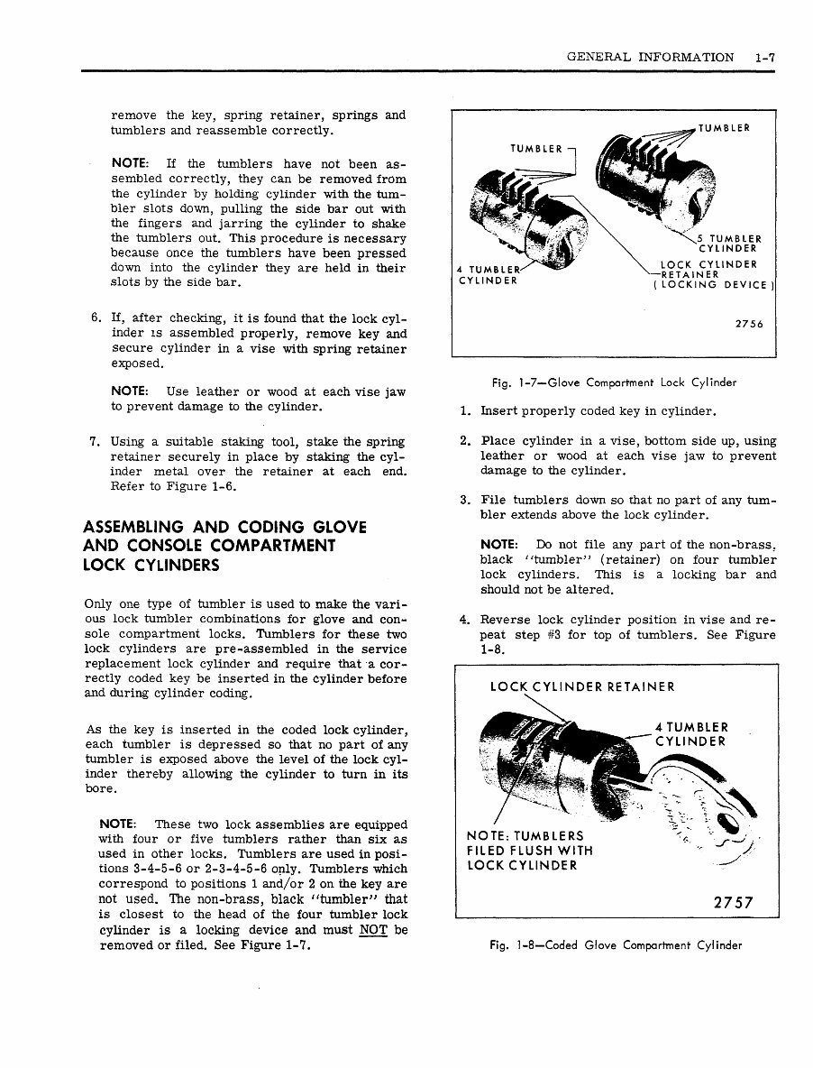
removed or filed. See Figure 1-7.
TUMBLER
TUMBLER
4 TUMBLER
CYLINDER
5 TUMBLER
CYLINDER
LOCK CYLINDER
RETAINER
( LOCKING DEVICE )
2756
Fig. 1-7—Glove Compartment Lock Cylinder
1. Insert properly coded key in cylinder.
2. Place cylinder in a vise, bottom side up, using
leather or wood at each vise jaw to prevent
damage to the cylinder.
3. File tumblers down so that no part of any tum-
bler extends above the lock cylinder.
NOTE: Do not file any part of the non-brass,
black "tumbler" (retainer) on four tumbler
lock cylinders. This is a locking bar and
should not be altered.
4. Reverse lock cylinder position in vise and re-
peat step #3 for top of tumblers. See Figure
1-8.
LOCK CYLINDER RETAINER
4 TUMBLER
CYLINDER
NOTE: TUMBLERS
FILED FLUSH WITH
LOCK CYLINDER
2757
Fig. 1-8—Coded Glove Compartment Cylinder
1-8 GENERAL INFORMATION
GLASS POLISHING
REMOVAL OF MINOR SCRATCHES
AND ABRASIONS-
Description
Minor glass scratches and abrasions can be effec-
tively removed or substantially reduced by utiliz-
ing the procedure and precautions presented in this
section. The phases of glass polishing discussed in
this section include the equipment required, the
recommended procedure and the precautions
necessary.
There are two. basic types of automotive glass:
(1) laminated safety plate (all windshield and sky-
light glass) and (2) solid tempered safety plate
(all side windows and back glass, except skylight).
A major concern in glass polishing is preventing
double vision from developing in areas that will
distort driver's vision. Eor this reason, less
polishing can be done on the windshield in the
driver's line of vision than in other areas. Dis-
• tortion is most likely to result when attempting to
remove deep scratches.
Glass polishing is an operation that must be per-
formed with reasonable care.
The equipment and procedures recommended here
were developed using cerium oxide compound
(Glass-Nu or equivalent). Follow the manufactur-
er's directions if other materials are used.
The following equipment is recommended for glass
polishing:
1. A low speed (600-1300 RPM) rotary polisher
(Skil Model #570 or equivalent).
2. A wool felt rotary-type polishing pad, approxi-
mately three inches in diameter and two inches
thick.
3. Powdered cerium oxide (Glass-Nu or equiva-
lent) mixed with water as the abrasive
compound.
4. A wide mouth container to hold, the polish.
Glass Polishing Procedure
1. Mix at least three heaping tablespoons of
cerium oxide (Glass-Nu or equivalent) with
sufficient water to obtain a creamy
consistency.
NOTE: If a larger proportion of cerium oxide
(Glass-Nu or equivalent) is used, the com-
pound cakes on the felt pad faster. If a small
proportion is used the polishing time required
will increase.
2. Agitate the mixture occasionally to maintain a
creamy consistency. The powdered cerium
oxide is insoluable in water and tends to
separate.
3. Draw a circle around the scratches on the
inside of the windshield with- a marking crayon
or equivalent. Draw other lines directly behind
scratches to serve as guides in locating the
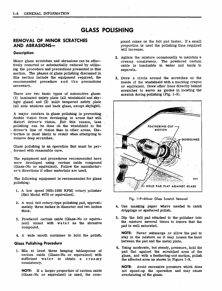
scratch during polishing (Fig. 1-9).
HOLD PAD FLAT AGAINST GLASS
Fig. 1-9—Minor Glass Scratch Removal
4. Use masking paper where needed to catch
drippings or spattered polish.
5. Dip the felt pad attached to the polisher into
the mixture several times to insure that the
pad is well saturated.
NOTE: Never submerge or allow the pad to
stay in the mixture as it may loosen the bond
between the pad and the metal plate.
6. Using moderate, but steady, pressure, hold the
pad flat against the scratched area of the
glass, and with a feathering-out motion, polish
the affected area as shown in Figure 1-9.
NOTE: Avoid excessive pressure which does
not speed-up the operation and may cause
overheating of the glass.
You're Reading a Preview
What's Included?
 Lifetime Access
Fast Download Speeds
Online & Offline Access
Access PDF Contents & Bookmarks
Full Search Facility
Print one or all pages of your manual
$31.99
1969 Fisher Body Service Manual
Viewed 77 Times Today

What's Included?
Lifetime Access
Fast Download Speeds
Online & Offline Access
Access PDF Contents & Bookmarks
Full Search Facility
Print one or all pages of your manual
$31.99

Secure transaction
What's Included?
Lifetime Access
Fast Download Speeds
Online & Offline Access
Access PDF Contents & Bookmarks
Full Search Facility
Print one or all pages of your manual
Description
1969 Fisher Body Service Manual
Models covered:
- Chevrolet
- Pontiac
- Oldsmobile
- Buick
- Cadillac
- Canada Acadian & Beaumont
- Canada Pontiac
- Chevelle
- Tempest
- F-85
- Special Deluxe
- Fleetwood Sixty Special
- Acadian
- Strato Chief
- Biscayne
- Tempest Custom
- Cutlass
- Skylark
- Fleetwood Brougham Sedan
- Beaumont
- Laurentian
- Bel Air
- Tempest LeMans
- Cutlass Supreme
- Skylark Custom
- Fleetwood Seventy-Five
- Deluxe
- Parisienne
- Impala
- Tempest Safari
- 442
- Sport Wagon
- Calais
- Custom
- 2+2
- Caprice
- Tempest GTO
- Custom Vista-Cruiser
- GS 400
- DeVille
- Grande Parisienne
- Camaro
- Catalina
- Delta 88
- Le Sabre
- Eldorado
- Chevy Nova
- Executive
- Delta Custom 88
- Le Sabre Custom
- Corvair "500"
- Bonnevile
- Delta Royale 88
- Wildcat
- Corvair Monza
- Firebird
- Ninety Eight
- Wildcat Custom
- Grand Prix
- Ninety Eight Luxury
- Electra "225"
- Toronado
- Electra "225" Custom
- Toronado Deluxe
- Riviera
Table of contents:
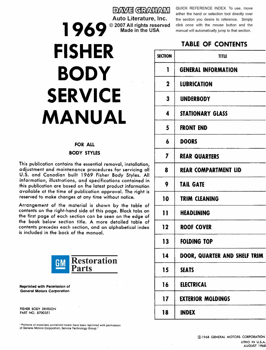
- General Information
- Lubrication
- Underbodody
- Stationary Glass
- Front End
- Doors
- Rear Quarters
- Rear Compartment Lid
- Tail Gate
- Trim Cleaning
- Headlining
- Roof Cover
- Folding Top
- Door, Quarter and Shelf Trim
- Seats
- Electrical
- Exterior Moldings
- Index
This manual is useful for both professional mechanics and DIY enthusiasts. It is comprehensive and complete, providing detailed instructions for various operations on the listed makes and models. Whether it's replacing the backup lamp on your 442, adjusting the side window glass on your GTO, or replacing the front window weatherstrip on your Chevelle SS, this manual is a must-have.
Format: .pdf
Printable: Yes
Language: English
Compatibility: Pretty much any electronic device, incl. PC & Mac computers, Android and Apple smartphones & tablet, etc.
Requirements: Adobe Reader (free)


