

Barcrest MPU4 Fruit machine Service manual
What's Included?
Fast Download Speeds
Online & Offline Access
Access PDF Contents & Bookmarks
Full Search Facility
Print one or all pages of your manual
0
r 21`244."' All`md1/4-d` j-1 .
ISSUE 2.0
This manual is intended primarily for the Field Service Engineer. The content is broadly
based in an attempt to cover all machines using the MPU4 system. References made to
some of the more detailed points may vary from model to model. The information is correct
for the majority of cases but ideally should be used in conjunction with the individual
information sheet supplied with each new machine.
The manual is divided into two parts. The first part provides the information necessary to
operate the machine, providing it is functioning correctly. The second part provides the
service information necessary to understand the workings and be capable of repairing the
equipment when things go wrong.
If after consulting this manual troubles are still being experienced, please do not hesitate to
contact our Technical Services Manager for further advice:
Technical Services Department,
Barcrest Limited,
William Street,
Ashton-under-Lyne,
Lancashire.
OL7 ORA
Telephone number: 061-339 0212
WARNING
240 volts is present within the machine. Only suitably qualified personnel should
carry out servicing. Disconnect mains lead before touching any internal
component.
The equipment to which this manual refers incorporates items protected by U.K. and Overseas patents.
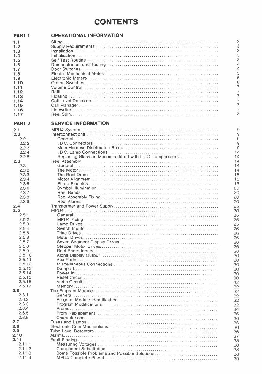
CONTENTS
PART 1 OPERATIONAL INFORMATION
1 .1 Siting............................................................................... 3
1.2 Supply Requirements............................................................... 3
1.3 Installation ......................................................................... 3
1 .4 Initialisation ........................................................................ 3
1 .5 Self Test Routine................................................................... 3
1.6 Demonstration and Testing .........................................................
4
1 .7 Door Switches...................................................................... 4
1.8 Electra Mechanical Meters ......................................................... 5
1.9 Electronic Meters .................................................................. 5
1.10 Option Switches.................................................................... 6
1.11 Volume Control..................................................................... 7
1.12 Refill ............................................................................... 7
1.13 Floating ............................................................................ 7
1.14 Coil Level Detectors................................................................ 7
1.15 Call Manager....................................................................... 7
1.16 Linewriter .......................................................................... 7
1.17 Reel Spin........................................................................... 8
PART 2 SERVICE INFORMATION
2 .1 MPU4 System ...................................................................... 9
2.2 Interconnections ................................................................... 9
2.2.1 General ......................................................................... 9
2.2.2 I.D.C. Connectors ............................................................... 9
2.2.3 Main Harness Distribution Board ................................................ 9
2.2.4 I.D.C. Lamp Connections ........................................................ 14
2.2.5 Replacing Glass on Machines fitted with I.D.C. Lampholders .................... 14
2 .3 Reel Assembly ..................................................................... 14
2.3.1 General ......................................................................... 14
2.3.2 The Motor ....................................................................... 14
2.3.3 The Reel Drum .................................................................. 15
2.3.4 Motor Alignment................................................................. 15
2.3.5 Photo Electrics .................................................................. 15
2.3.6 Symbol Illumination ............................................................. 20
2.3.7 Reel Bands...................................................................... 20
2.3.8 Reel Assembly Fixing............................................................ 20
2.3.9 Reel Alarms ................................................................... 20
2.4 Transformer and Power Supply ..................................................... 25
2 .5 MPU4 .............................................................................. 25
2.5.1 General ......................................................................... 25
2.5.2 MPU4 Fixing .................................................................... 25
2.5.3 Lamp Drives..................................................................... 25
2.5.4 Switch Inputs.................................................................... 26
2.5.5 Triac Drives ..................................................................... 26
2.5.6 Meter Drives .................................................................... 26
2.5.7 Seven Segment Display Drives.................................................. 26
2.5.8 Stepper Motor Drives............................................................ 26
2.5.9 Reel Photo Inputs ............................................................... 26
2.5.10 Alpha Display Output .......................................................... 30
2.5.11 Aux Ports........................................................................ 30
2.5.12
Miscellaneous Connections ..................................................... 30
2.5.13
Dataport......................................................................... 30
2.5.14 Power In ........................................................................ 30
2.5.15 Reset Circuit
.................................................................... 30
2.5.16 Audio Circuit .................................................................... 32
2.5.17 Memory ......................................................................... 32
2.6 The Program Module ...............................................................
32
2.6.1 General ......................................................................... 32
2.6.2 Program Module Identification...................................................
32
2.6.3 Program Modifications .......................................................... 32
2.6.4 Prams ........................................................................... 34
2.6.5 Prom Replacement..............................................................
36
2.6.6 Characteriser....................................................................
36
2.7 Fuses and Lamps ..................................................................
36
2.8 Electronic Coin Mechanisms .......................................................
36
2.9 Tube Level Detectors...............................................................
36
2.10
Alarms..............................................................................
37
2.11 Fault Finding .......................................................................
38
2.11.1 Measuring Voltages .............................................................
38
2.11.2 Component Substitution.........................................................
38
2.11.3
Some Possible Problems and Possible Solutions ................................
38
2.11.4 MPU4 Complete Pinout ......................................................... 39
OPERATIONAL INFORMATION
PART 1
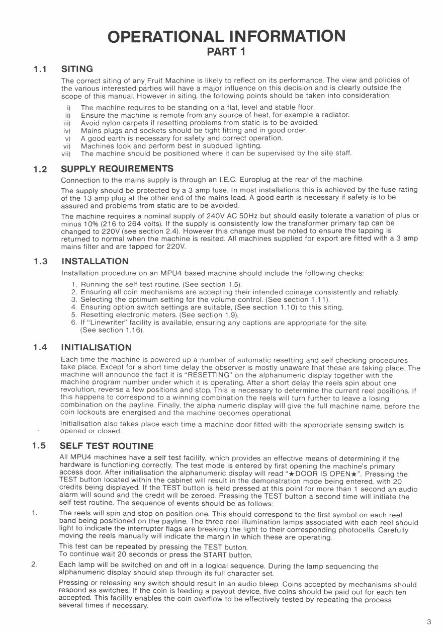
1.1 SITING
The correct siting of any . Fruit Machine is likely to reflect on its performance. The view and policies of
the various interested parties will have a major influence on this decision and is clearly outside the
scope of this manual. However in siting, the following points should be taken into consideration:
i) The machine requires to be standing on a flat, level and stable floor.
ii) Ensure the machine is remote from any source of heat, for example a radiator.
iii) Avoid nylon carpets if resetting problems from static is to be avoided.
iv) Mains plugs and sockets should be tight fitting and in good order.
v) A good earth is necessary for safety and correct operation.
vi) Machines look and perform best in subdued lighting.
vii) The machine should be positioned where it can be supervised by the site staff.
1.2 SUPPLY REQUIREMENTS
Connection to the mains supply is through an I.E.C. Europlug at the rear of the machine.
The supply should be protected by a 3 amp fuse. In most installations this is achieved by the fuse rating
of the 13 amp plug at the other end of the mains lead. A good earth is necessary if safety is to be
assured and problems from static are to be avoided.
The machine requires a nominal supply of 240V AC 50Hz but should easily tolerate a variation of plus or
minus 10% (216 to 264 volts). If the supply is consistently low the transformer primary tap can be
changed to 220V (see section 2.4). However this change must be noted to ensure the tapping is
returned to normal when the machine is resited. All machines supplied for export are fitted with a 3 amp
mains filter and are tapped for 220V.
1.3 INSTALLATION
Installation procedure on an MPU4 based machine should include the following checks:
1. Running the self test routine. (See section 1.5).
2. Ensuring all coin mechanisms are accepting their intended coinage consistently and reliably.
3. Selecting the Optimum setting for the volume control. (See section 1.11).
4. Ensuring option switch settings are suitable, (See section 1.10) to this siting.
5. Resetting electronic meters. (See section 1.9).
6. If "Linewriter" facility is available, ensuring any captions are appropriate for the site.
(See section 1.16).
1.4 INITIALISATION
Each time the machine is powered up a number of automatic resetting and self checking procedures
take place. Except for a short time delay the observer is mostly unaware that these are taking place. The
machine will announce the fact it is "RESETTING" on the alphanumeric display together with the
machine program number under which it is operating. After a short delay the reels spin about one
revolution, reverse a few positions and stop. This is necessary to determine the current reel positions. If
this happens to correspond to a winning combination the reels will turn further to leave a losing
combination on the payline. Finally, the alpha numeric display will give the full machine name, before the
coin lockouts are energised and the machine becomes operational.
Initialisation also takes place each time a machine door fitted with the appropriate sensing switch is
opened or closed.
1.5 SELF TEST ROUTINE
All MPU4 machines have a self test facility, which provides an effective means of determining if the
hardware is functioning correctly. The test mode is entered by first opening the machine's primary
access door. After initialisation the alphanumeric display will read "*DOOR IS OPEN*". Pressing the
TEST button located within the cabinet will result in the demonstration mode being entered, with 20
credits being displayed. If the TEST button is held pressed at this point for more than 1 second an audio
alarm will sound and the credit will be zeroed. Pressing the TEST button a second time will initiate the
self test routine. The sequence of events should be as follows:
1.
The reels will spin and stop on position one. This should correspond to the first symbol on each reel
band being positioned on the payline. The three reel illumination lamps associated with each reel should
light to indicate the interrupter flags are breaking the light to their corresponding photocells. Carefully
moving the reels manually will indicate the margin in which these are operating.
This test can be repeated by pressing the TEST button.
To continue wait 20 seconds or press the START button.
2.
Each lamp will be switched on and off in a logical sequence. During the lamp sequencing the
alphanumeric display should step through its full character set.
Pressing or releasing any switch should result in an audio bleep. Coins accepted by mechanisms should
respond as switches. If the coin is feeding a payout device, five coins should be paid out for each ten
accepted. This facility enables the coin overflow to be effectively tested by repeating the process
several times if necessary.
3
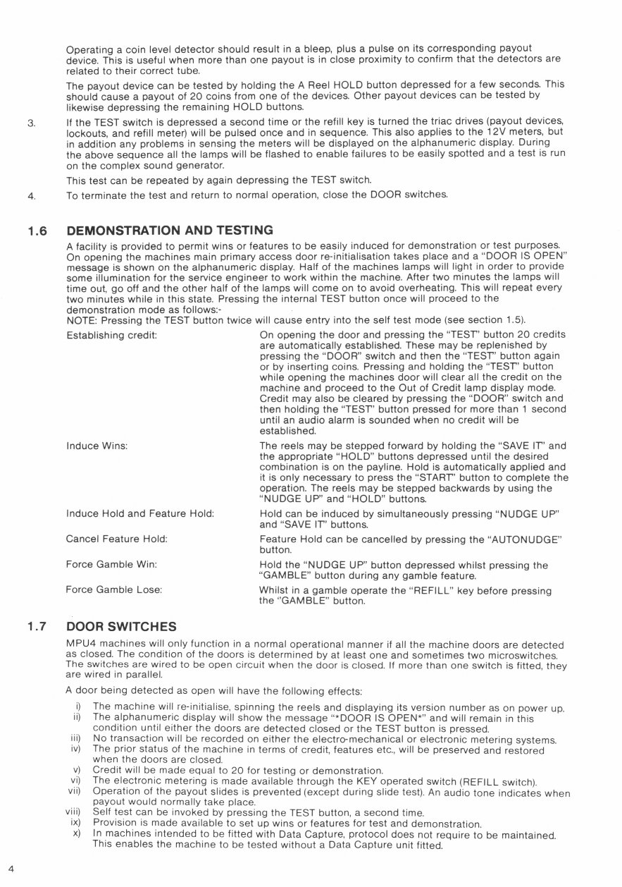
Operating a coin level detector should result in a bleep, plus a pulse on its corresponding payout
device. This is useful when more than one payout is in close proximity to confirm that the detectors are
related to their correct tube.
The payout device can be tested by holding the A Reel HOLD button depressed for a few seconds. This
should cause a payout of 20 coins from one of the devices. Other payout devices can be tested by
likewise depressing the remaining HOLD buttons.
If the TEST switch is depressed a second time or the refill key is turned the triac drives (payout devices,
lockouts, and refill meter) will be pulsed once and in sequence. This also applies to the 12V meters, but
in addition any problems in sensing the meters will be displayed on the alphanumeric display. During
the above sequence all the lamps will be flashed to enable failures to be easily spotted and a test is run
on the complex sound generator.
This test can be repeated by again depressing the TEST switch.
4.
To terminate the test and return to normal operation, close the DOOR switches.
1.6 DEMONSTRATION AND TESTING
A facility is provided to permit wins or features to be easily induced for demonstration or test purposes.
On opening the machines main primary access door re-initialisation takes place and a "DOOR IS OPEN"
message is shown on the alphanumeric display. Half of the machines lamps will light in order to provide
some illumination for the service engineer to work within the machine. After two minutes the lamps will
time out, go off and the other half of the lamps will come on to avoid overheating. This will repeat every
two minutes while in this state. Pressing the internal TEST button once will proceed to the
demonstration mode as follows:-
NOTE: Pressing the TEST button twice will cause entry into the self test mode (see section 1.5).
Establishing credit: On opening the door and pressing the "TEST' button 20 credits
are automatically established. These may be replenished by
pressing the "DOOR" switch and then the "TEST" button again
or by inserting coins. Pressing and holding the "TEST' button
while opening the machines door will clear all the credit on the
machine and proceed to the Out of Credit lamp display mode.
Credit may also be cleared by pressing the "DOOR" switch and
then holding the "TEST" button pressed for more than 1 second
until an audio alarm is sounded when no credit will be
established.
Induce Wins: The reels may be stepped forward by holding the "SAVE IT' and
the appropriate "HOLD" buttons depressed until the desired
combination is on the payline. Hold is automatically applied and
it is only necessary to press the "START" button to complete the
operation. The reels may be stepped backwards by using the
"NUDGE UP" and "HOLD" buttons.
Induce Hold and Feature Hold: Hold can be induced by simultaneously pressing "NUDGE UP"
and "SAVE IT' buttons.
Cancel Feature Hold: Feature Hold can be cancelled by pressing the "AUTONUDGE"
button.
Force Gamble Win: Hold the "NUDGE UP" button depressed whilst pressing the
"GAMBLE" button during any gamble feature.
Force Gamble Lose:
Whilst in a gamble operate the "REFILL" key before pressing
the "GAMBLE" button.
1.7 DOOR SWITCHES
MPU4 machines will only function in a normal operational manner if all the machine doors are detected
as closed. The condition of the doors is determined by at least one and sometimes two microswitches.
The switches are wired to be open circuit when the door is closed. If more than one switch is fitted, they
are wired in parallel.
A door being detected as open will have the following effects:
i) The machine will re-initialise, spinning the reels and displaying its version number as on power up.
ii) The alphanumeric display will show the message *DOOR
IS
OPEN*'
and will remain in this
condition until either the doors are detected closed or the TEST button is pressed.
iii)
No transaction will be recorded on either the electro-mechanical or electronic metering systems.
iv) The prior status of the machine in terms of credit, features etc., will be preserved and restored
when the doors are closed.
v) Credit will be made equal to 20 for testing or demonstration.
vi) The electronic metering is made available through the KEY operated switch (REFILL switch).
vii)
Operation of the payout slides is prevented (except during slide test). An audio tone indicates when
payout would normally take place.
viii) Self test can be invoked by pressing the TEST button, a second time.
ix) Provision is made available to set up wins or features for test and demonstration.
x)
In machines intended to be fitted with Data Capture, protocol does not require to be maintained.
This enables the machine to be tested without a Data Capture unit fitted.
4
1.8
1.9
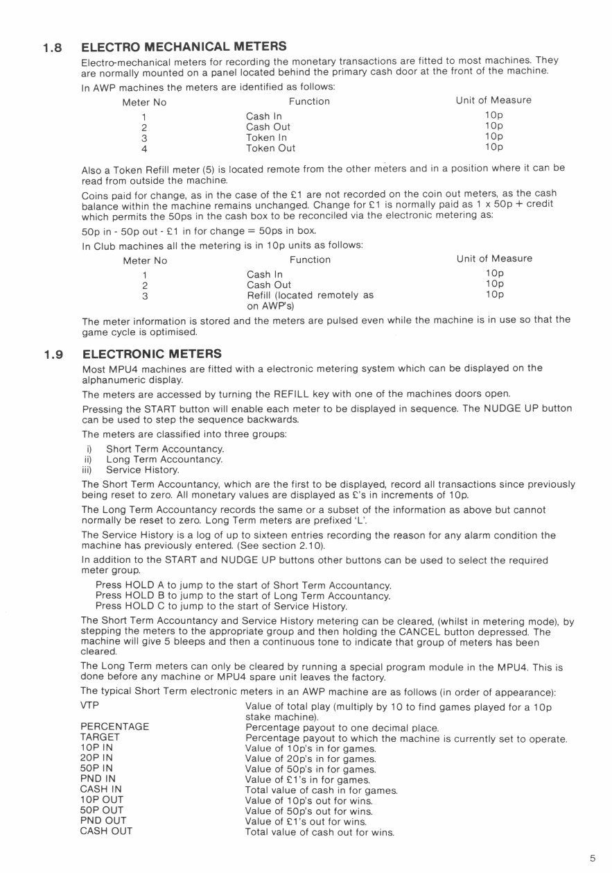
ELECTRO MECHANICAL METERS
Electro-mechanical meters for recording the monetary transactions are fitted to most machines. They
are normally mounted on a panel located behind the primary cash door at the front of the machine.
In AWP machines the meters are identified as follows:
Meter No Function Unit of Measure
1 Cash In
lOp
2 Cash Out
lOp
3 Token In
lOp
4 Token Out
lOp
Also a Token Refill meter (5) is located remote from the other meters and in a position where it can be
read from outside the machine.
Coins paid for change, as in the case of the Li are not recorded on the coin out meters, as the cash
balance within the machine remains unchanged. Change for £1 is normally paid as 1 x 50p + credit
which permits the 50ps in the cash box to be reconciled via the electronic metering as:
50p in - 50p out - Li in for change = 50ps in box.
In Club machines all the metering is in 1 Op units as follows:
Meter No Function
Unit of Measure
1 Cash In
lOp
2 Cash Out
lOp
3 Refill (located remotely as
lOp
on AWP's)
The meter information is stored and the meters are pulsed even while the machine is in use so that the
game cycle is optimised.
ELECTRONIC METERS
Most MPU4 machines are fitted with a electronic metering system which can be displayed on the
alphanumeric display.
The meters are accessed by turning the REFILL key with one of the machines doors open.
Pressing the START button will enable each meter to be displayed in sequence. The NUDGE UP button
can be used to step the sequence backwards.
The meters are classified into three groups:
i) Short Term Accountancy.
ii) Long Term Accountancy.
iii) Service History.
The Short Term Accountancy, which are the first to be displayed, record all transactions since previously
being reset to zero. All monetary values are displayed as L's in increments of lOp.
The Long Term Accountancy records the same or a subset of the information as above but cannot
normally be reset to zero. Long Term meters are prefixed 'L'.
The Service History is a log of up to sixteen entries recording the reason for any alarm condition the
machine has previously entered. (See section 2.10).
In addition to the START and NUDGE UP buttons other buttons can be used to select the required
meter group.
Press HOLD A to jump to the start of Short Term Accountancy.
Press HOLD B to jump to the start of Long Term Accountancy.
Press HOLD C to jump to the start of Service History.
The Short Term Accountancy and Service History metering can be cleared, (whilst in metering mode), by
stepping the meters to the appropriate group and then holding the CANCEL button depressed. The
machine will give 5 bleeps and then a continuous tone to indicate that group of meters has been
cleared.
The Long Term meters can only be cleared by running a special program module in the MPU4. This is
done before any machine or MPU4 spare unit leaves the factory.
The typical Short Term electronic meters in an AWP machine are as follows (in order of appearance):
VTP
Value of total play (multiply by 10 to find games played for a 1 Op
stake machine).
PERCENTAGE
Percentage payout to one decimal place.
TARGET
Percentage payout to which the machine is currently set to operate.
lop IN Value of lOp's in for games.
20P IN Value of 20p's in for games.
50P IN
Value of 50p's in for games.
PND IN Value of 9-l's in for games.
CASH IN
Total value of cash in for games.
lop OUT Value of lOp's out for wins.
50P OUT
Value of 50p's out for wins.
PND OUT Value of Ll 's out for wins.
CASH OUT Total value of cash out for wins.
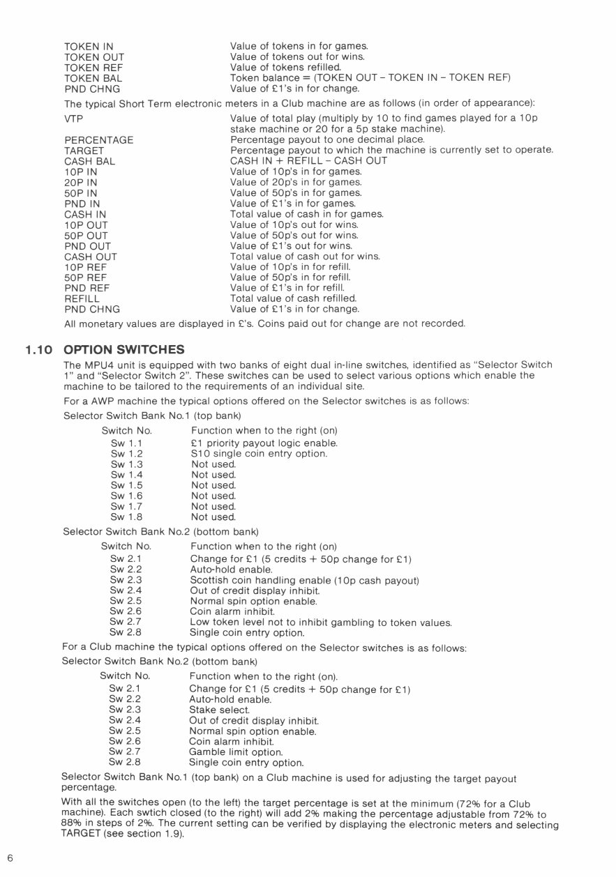
TOKEN IN Value of tokens in for games.
TOKEN OUT Value of tokens out for wins.
TOKEN REF Value of tokens refilled.
TOKEN BAL Token balance = (TOKEN OUT - TOKEN IN - TOKEN REF)
PND CHNG Value of El's in for change.
The typical Short Term electronic meters in a Club machine are as follows (in order of appearance):
VTP Value of total play (multiply by 10 to find games played for a 1 O
stake machine or 20 for a 5p stake machine).
PERCENTAGE Percentage payout to one decimal place.
TARGET Percentage payout to which the machine is currently set to operate.
CASH BAL CASH IN + REFILL - CASH OUT
lop IN Value of lOp's in for games.
20P IN Value of 20p's in for games.
50P IN Value of 50p's in for games.
PND IN Value of Li's in for games.
CASH IN Total value of cash in for games.
lop OUT Value of lOp's out for wins.
50P OUT Value of 50p's out for wins.
PND OUT Value of El's out for wins.
CASH OUT Total value of cash out for wins.
lOP REF Value of lOp's in for refill.
50P REF Value of 50p's in for refill.
PND REF Value of El's in for refill.
REFILL Total value of cash refilled.
PND CHNG Value of Li's in for change.
All monetary values are displayed in L's. Coins paid out for change are not recorded
1.10 OPTION SWITCHES
The MPU4 unit is equipped with two banks of eight dual in-line switches, identified as "Selector Switch
i' and "Selector Switch 2". These switches can be used to select various options which enable the
machine to be tailored to the requirements of an individual site.
For a AWP machine the typical options offered on the Selector switches is as follows:
Selector Switch Bank No.i (top bank)
Switch No. Function when to the right (on)
Sw 1.1 Li priority payout logic enable.
Sw 1.2 S1 single coin entry option.
Sw 1.3 Not used.
Sw 1.4 Not used.
Sw 1.5 Not used.
Sw 1.6 Not used.
Swi.7 Not used.
Sw 1.8 Not used.
Selector Switch Bank No.2 (bottom bank)
Switch No. Function when to the right (on)
Sw 2.1 Change for Li (5 credits + 50p change for Li)
Sw 2.2 Auto-hold enable.
Sw 2.3 Scottish coin handling enable (1 Op cash payout)
Sw 2.4 Out of credit display inhibit.
Sw 2.5 Normal spin option enable.
Sw 2.6 Coin alarm inhibit.
Sw 2.7 Low token level not to inhibit gambling to token values.
Sw 2.8 Single coin entry option.
For a Club machine the typical options offered on the Selector switches is as follows:
Selector Switch Bank No.2 (bottom bank)
Switch No. Function when to the right (on).
Sw 2.1 Change for Li (5 credits + 50p change for Li)
Sw 2.2 Auto-hold enable.
Sw 2.3 Stake select.
Sw 2.4 Out of credit display inhibit.
Sw 2.5 Normal spin option enable.
Sw 2.6 Coin alarm inhibit.
Sw 2.7 Gamble limit option.
Sw 2.8 Single coin entry option.
Selector Switch Bank No.1 (top bank) on a Club machine is used for adjusting the target payout
percentage.
With all the switches open (to the left) the target percentage is set at the minimum (72% for a Club
machine). Each swtich closed (to the right) will add 2% making the percentage adjustable from 72% to
88% in steps of 2%. The current setting can be verified by displaying the electronic meters and selecting
TARGET (see section 1.9).
M .
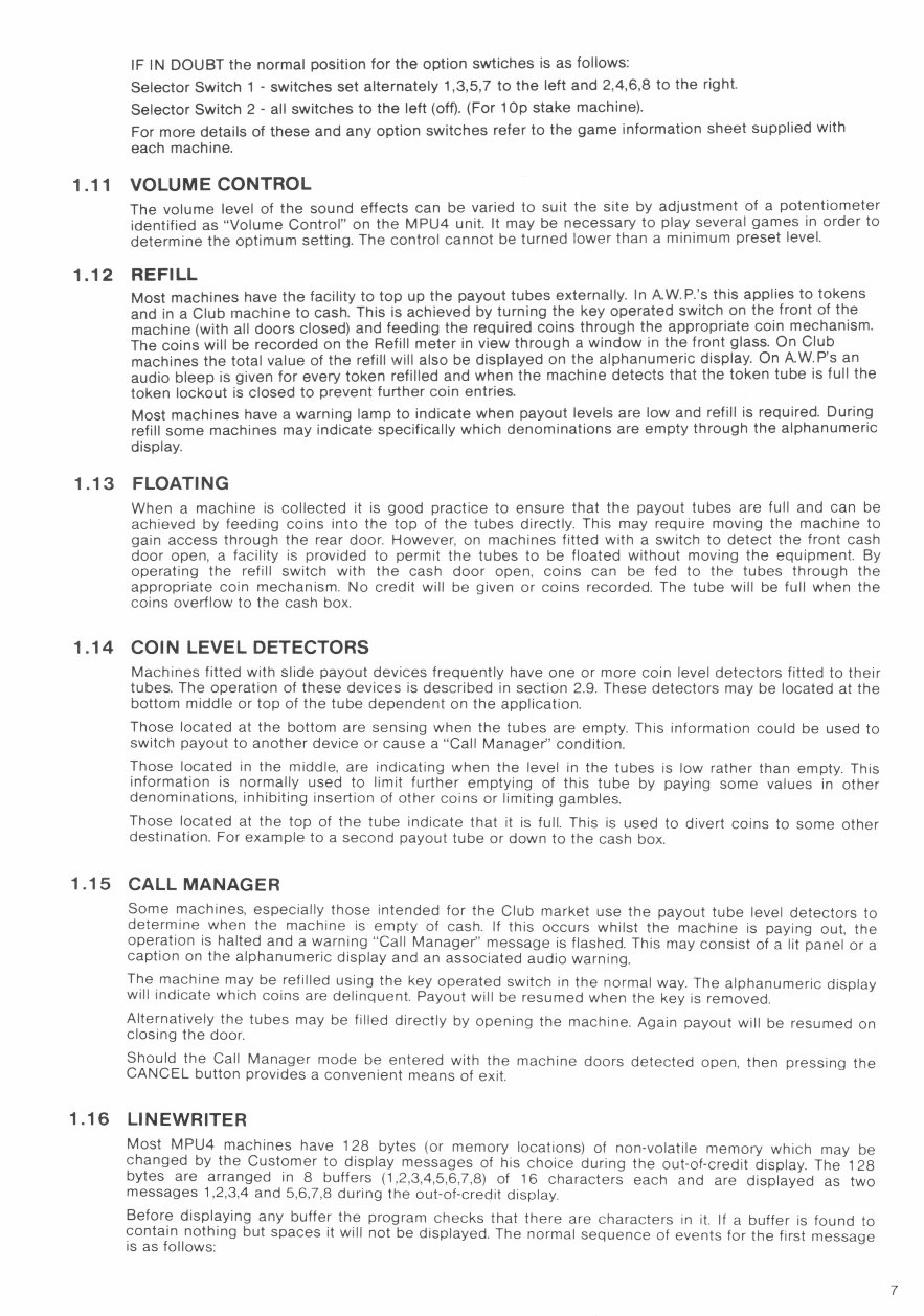
IF IN DOUBT the normal position for the option swtiches is as follows:
Selector Switch 1 - switches set alternately 1,3,5,7 to the left and 2,4,6,8 to the right.
Selector Switch 2 - all switches to the left (off). (For 1 Op stake machine).
For more details of these and any option switches refer to the game information sheet supplied with
each machine.
1.11 VOLUME CONTROL
The volume level of the sound effects can be varied to suit the site by adjustment of a potentiometer
identified as 'Volume Control" on the MPU4 unit. It may be necessary to play several games in order to
determine the optimum setting. The control cannot be turned lower than a minimum preset level.
1.12 REFILL
Most machines have the facility to top up the payout tubes externally. In AW.P.'s this applies to tokens
and in a Club machine to cash. This is achieved by turning the key operated switch on the front of the
machine (with all doors closed) and feeding the required coins through the appropriate coin mechanism.
The coins will be recorded on the Refill meter in view through a window in the front glass. On Club
machines the total value of the refill will also be displayed on the alphanumeric display. On AW.P's an
audio bleep is given for every token refilled and when the machine detects that the token tube is full the
token lockout is closed to prevent further coin entries.
Most machines have a warning lamp to indicate when payout levels are low and refill is required. During
refill some machines may indicate specifically which denominations are empty through the alphanumeric
display.
1.13 FLOATING
When a machine is collected it is good practice to ensure that the payout tubes are full and can be
achieved by feeding coins into the top of the tubes directly. This may require moving the machine to
gain access through the rear door. However, on machines fitted with a switch to detect the front cash
door open, a facility is provided to permit the tubes to be floated without moving the equipment. By
operating the refill switch with the cash door open, coins can be fed to the tubes through the
appropriate coin mechanism. No credit will be given or coins recorded. The tube will be full when the
coins overflow to the cash box.
1.14 COIN LEVEL DETECTORS
Machines fitted with slide payout devices frequently have one or more coin level detectors fitted to their
tubes. The operation of these devices is described in section 2.9. These detectors may be located at the
bottom middle or top of the tube dependent on the application.
Those located at the bottom are sensing when the tubes are empty. This information could be used to
switch payout to another device or cause a "Call Manager" condition.
Those located in the middle, are indicating when the level in the tubes is low rather than empty. This
information is normally used to limit further emptying of this tube by paying some values in other
denominations, inhibiting insertion of other coins or limiting gambles.
Those located at the top of the tube indicate that it is full. This is used to divert coins to some other
destination. For example to a second payout tube or down to the cash box.
1.15 CALL MANAGER
Some machines, especially those intended for the Club market use the payout tube level detectors to
determine when the machine is empty of cash. If this occurs whilst the machine is paying out, the
operation is halted and a warning "Call Manager" message is flashed. This may consist of a lit panel or a
caption on the alphanumeric display and an associated audio warning.
The machine may be refilled using the key operated switch in the normal way. The alphanumeric display
will indicate which coins are delinquent. Payout will be resumed when the key is removed.
Alternatively the tubes may be filled directly by opening the machine. Again payout will be resumed on
closing the door.
Should the Call Manager mode be entered with the machine doors detected open, then pressing the
CANCEL button provides a convenient means of exit.
1.16 LINEWRITER
Most MPU4 machines have 128 bytes (or memory locations) of non-volatile memory which may be
changed by the Customer to display messages of his choice during the out-of-credit display. The 128
bytes are arranged in 8 buffers (1,2,3,4,5,6,7,8) of 16 characters each and are displayed as two
messages 1,2,3,4 and 5,6,7,8 during the out-of-credit display.
Before displaying any buffer the program checks that there are characters in it. If a buffer is found to
contain nothing but spaces it will not be displayed. The normal sequence of events for the first message
is as follows:
7
Buffer 1 is tested to see if it contains anything, if it does it is faded on and then off.
Buffer 2 is tested to see if it contains anything, if it does it is faded on and then off.
Buffer 3 is tested to see if it contains anything, if it does it is faded on and then off.
Buffer 4 is tested to see if it contains anything, if it does it is faded on and then off.
From this it can be seen that if all four buffers in a message are clear no message will be displayed.
In order to allow the customer to change the contents of these buffers an Editor has been provided. To
use the Editor the back door is opened, the REFILL key turned and the TEST button pressed. The
display will show 'BUFFER 1" and then display the contents of the buffer. This is the first of the eight
buffers. To step to the next buffer press the COLLECT button and to step to the previous buffer press
the GAMBLE button.
A full stop is used within the buffer as a cursor to show which character is being edited. This cursor may
be moved to the next character by pressing the HOLD C button. On reaching the extreme right of the
buffer it will wrap-around and re-appear at the left hand side. To enter or change a character in the
buffer use HOLD C to step the cursor to the correct point, and press either HOLD A, which will cause
the character at that point to step up through the alphabet, or HOLD B, which will cause it to step down.
The CANCEL button may be used at any time to clear the whole of the buffer being displayed.
PLEASE NOTE: full stops and commas are individual characters requiring one byte each in the buffer.
Before attempting to enter a message into the buffers it is recommended that the text is worked out first
on paper to see it it will fit into blocks of 16 characters, and how best to distribute it between the
buffers.
Once a message has been entered and any unused buffers cleared the second message can be
entered into buffers 5,6,7,8. When both messages have been entered turn the REFILL key back to its
normal position. Invoke the out-of-credit display and the messages will be displayed.
On switch-on the program checks the contents of the buffers against a checksum byte and if they have
become corrupted it clears them all out.
1.17 REELSPIN
The speed of the reel spin can be selected Normal or Fast, by Option Switch 5 on Selector Switch 2.
(Left = Fast, Right = Normal). In the Fast position the spin is as fast as possible for the shortest game
cycle. In the Normal position, the reels are rotated slower for a longer game cycle which can be more
acceptable in some situations.
In sites where the supply voltage is below nominal (240v) then some problems with running of the fast
speed may be experienced. If in doubt select normal spin.
WARNING
240 volts is present within the machine. Only suitably qualified personnel should
carry out servicing. Disconnect mains lead before touching any internal
components.
SERVICE INFORMATION
PART 2
2.1 MPU4 SYSTEM
The MPU4 System comprises a number of key components which in combination provide a flexible
reliable and economical solution for todays fruit machine.
The Key components are as follows:
i) MPU4 control unit.
ii) MPU4 program module.
iii)
MPU4 reel assembly (3, 4 and 5 reels)
iv) MPU4 transformer/power supply.
All machines using the MPU4 System use essentially the same four items listed above and are entirely
interchangeable between machine types. The advantages to this approach are obvious and have been
well demonstrated with our previous MPU Systems.
Key MPU4 components are not interchangeable with previous Barcrest MPU Systems.
2.2 INTERCONNECTIONS
2.2.1 GENERAL
Fig.1 shows how the various components are connected within a typical MPU4 machine. The lamps are
connected to the MPU4 via a distribution board which in turn is linked to the MPU4 via two jumpers. All
machines however still use a cable harness to connect the button lamps, switches, speaker and
solenoids. Some machines do not use a distribution board but rely on a main cable harness to connect
all the lamps, switches etc.
Other items, reels, displays, meters, transformers, electronic coin mechs, and data capture are interfaced
through individual jumpers and simple extension harnesses. Connections to the MPU4 are given in more
detail in Fig.2
2.2.2 I.D.C. CONNECTORS
All connections from the unit, with the exception of the Dataport are through 156 type in-line
connectors. The header (male pins) are positioned around the periphery of the printed circuit board to
provide good mechanical support and minimise flexing. The 156 refers to the pitch of the pins, 0.156
inches or 3/16.
Wires to the MPU4 are terminated in female housings using normally I.D.C. or alternatively, crimped
connections. I.D.C. (or insulation displacement connection) is a relatively new method of termination
which offers advantages of reliability and economy. The wire is forced into a 'U' groove in the terminal
which displaces the insulation and makes contact with the conductor underneath. The colour of the
nylon housing indicates for which gauge of wire the 'U' groove is designed. In the case of MPU4 most
wires are 13/02 and therefore most of the I.D.C. housings are coloured red.
The in-line I.D.C. connectors are identified in three ways:
1. The number of ways - which varies from 4 to 24.
2. The colour of the cap - a colour coded cover is clipped into each housing which holds
the wires into location.
3. The position of the key
- has to match a missing male pin on the header.
Crimped in-line connectors are identified in a similar way, except the colour coding is applied to the
body of the housing rather than the cap.
Correct orientation of the connectors is clearly determined by physical constraints and key location. Pin
number identification is moulded onto the side of the housing.
It should be noted that the jumper links in the case of a 5 way for example are connected
1 - 1
1 - 1
2 - 2
2 - 2
Not 3 - 3 but 3 - 3
key - key
key - key
5 - 5
5 - 5
Therefore the jumpers are handed and can only be physically connected in on
direction.
2.2.3 MAIN HARNESS DISTRIBUTION BOARD
The main harness distribution board is shown in Fig. 1.1. It consists of eight male I.D.C. headers that are
used to connect the machines lamps to the MPU4.
The distribution board is connected to the MPU4 by two jumpers. The 17 way blue jumper carries the
lamps selects and the 17 way green jumper carries the lamp drives. Connections for the top and bottom
glass lamps in the machine are made via the three pairs of 17 headers at the top of the board. The 17
blue and 17 way green connectors for the lamps are connected to the jumpers from the MPU4 in a 1 to
1 link.
The lamp selects and drives needed for the reel back lights are brought out via a 9 way header at the
bottom of the board. This is connected to the backplane board on the reel assembly via a blue jumper.
This jumper uses only eight of the nine ways on 3 and 4 reel machines and all nine on 5 reel machines.
You're Reading a Preview
What's Included?
Fast Download Speeds
Online & Offline Access
Access PDF Contents & Bookmarks
Full Search Facility
Print one or all pages of your manual
$30.99
$40.99
Viewed 70 Times Today


Secure transaction
What's Included?
Fast Download Speeds
Online & Offline Access
Access PDF Contents & Bookmarks
Full Search Facility
Print one or all pages of your manual
$30.99
$40.99
Get your hands on the comprehensive service manual for the Barcrest MPU4 Fruit machine. This A4-sized manual is an invaluable resource for both professional Tech Doctors and owners of Barcrest MPU4 Fruit machines. Whether you're a seasoned mechanic or a DIY enthusiast, this manual equips you with the technical information needed for effective repairs and maintenance.
Additionally, the Blackout Instruction Booklet is also available in .PDF format, providing further support for troubleshooting and upkeep.
Consider joining our affiliate program, where you can earn 20% on all sales. Easily integrate widgets into your website and take advantage of bulk manual sales for traders.


