Page No. Contents Section 1 - General Information 1-i 1-i Introduction About this Manual ...................................................................................... 1-1 Machine Model and Serial Number ....................................................... 1-1 Using the Service Manual ..................................................................... 1-1 Section Numbering ................................................................................ 1-1 Left Side, Right Side .............................................................................. 1-2 Cross References .................................................................................. 1-2 Identifying your Machine ............................................................................ 1-3 Machine Identification Plate .................................................................. 1-3 Component Identification Plates ............................................................ 1-4 Torque Settings Zinc Plated Fasteners and Dacromet Fasteners ....................................... 1-7 Introduction ............................................................................................ 1-7 Bolts and Screws ................................................................................... 1-7 Hydraulic Connections ............................................................................. 1-11 'O' Ring Face Seal System .................................................................. 1-11 'Torque Stop' Hose System ................................................................. 1-14 Service Tools Numerical List .......................................................................................... 1-15 Tool Detail Reference .............................................................................. 1-16 Section B - Body and Framework ........................................................ 1-16 Section C - Electrics ............................................................................ 1-20 Section E - Hydraulics ......................................................................... 1-23 Section H - Steering ............................................................................ 1-31 Section K - Engine ............................................................................... 1-32 Service Consumables Sealing and Retaining Compounds ......................................................... 1-35 Terms and Definitions Colour Coding .......................................................................................... 1-37 Hydraulic Schematic Colour Codes ..................................................... 1-37
Page No. Contents Section 1 - General Information 1-ii 1-ii
Section 1 - General Information 1-1 1-1 9803/9520-07 Introduction About this Manual Machine Model and Serial Number This manual provides information for the following model(s) in the JCB machine range: – TM310, TM310S and TM310WM from machine serial number 1314700. Using the Service Manual T11-004 This publication is designed for the benefit of JCB Distributor Service Engineers who are receiving, or have received, training by JCB Technical Training Department. These personnel should have a sound knowledge of workshop practice, safety procedures, and general techniques associated with the maintenance and repair of hydraulic earthmoving equipment. The illustrations in this publication are for guidance only. Where the machines differ, the text and/or the illustration will specify. General warnings in Section 2 are repeated throughout the manual, as well as specific warnings. Read all safety statements regularly, so you do not forget them. Renewal of oil seals, gaskets, etc., and any component showing obvious signs of wear or damage is expected as a matter of course. It is expected that components will be cleaned and lubricated where appropriate, and that any opened hose or pipe connections will be blanked to prevent excessive loss of hydraulic fluid and ingress of dirt. Where a torque setting is given as a single figure it may be varied by plus or minus 3%. Torque figures indicated are for dry threads, hence for lubricated threads may be reduced by one third. The manufacturer's policy is one of continuous improvement. The right to change the specification of the machine without notice is reserved. No responsibility will be accepted for discrepancies which may occur between specifications of the machine and the descriptions contained in this publication. Finally, please remember above all else safety must come first! Section Numbering T11-005 The manual is compiled in sections, the first three are numbered and contain information as follows: The remaining sections are alphabetically coded and deal with Dismantling, Overhaul etc. of specific components, for example: Section contents, technical data, circuit descriptions, operation descriptions etc. are inserted at the beginning of each alphabetically coded section. 1 General Information - includes torque settings and service tools. 2 Care and Safety - includes warnings and cautions pertinent to aspects of workshop procedures etc. 3 Maintenance - includes service schedules and recommended lubricants for all the machine. A Attachments B Body and Framework, etc.
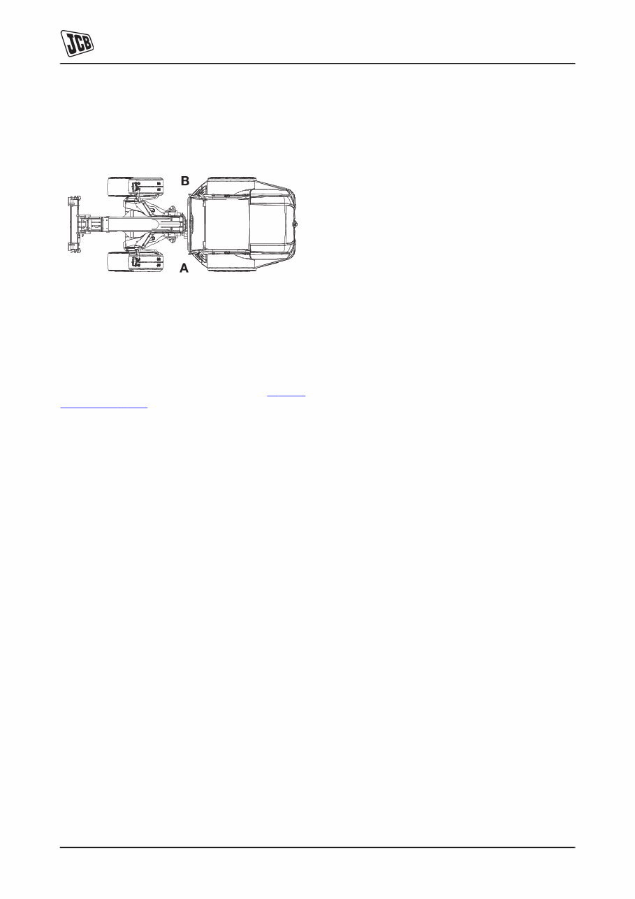
Section 1 - General Information Introduction About this Manual 1-2 1-2 9803/9520-07 Left Side, Right Side In this manual, 'left' A and 'right' B mean your left and right when you are seated correctly in the machine. C087420 Fig 1. Cross References T1-004_2 In this publication, page cross references are made by presenting the subject title printed in bold, italic and underlined. It is preceeded by the 'go to' symbol. The number of the page upon which the subject begins, is indicated within the brackets. For example: K Cross References ( T 1-2) .
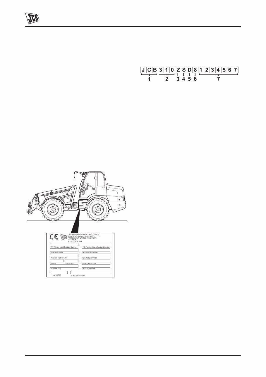
Section 1 - General Information Introduction Identifying your Machine 1-3 1-3 9803/9520-07 Identifying your Machine Machine Identification Plate Your machine has an identification plate mounted as shown. The serial numbers of the machine and its major units are stamped on the plate. Note: The machine model and build specification is indicated by the VIN (earlier machines) or PIN (later machines). Refer to Typical Vehicle Identification Number (VIN) or Typical Product Identification Number (PIN). The serial number of each major unit is also stamped on the unit itself. If a major unit is replaced by a new one, the serial number on the identification plate will be wrong. Either stamp the new number of the unit on the identification plate, or simply stamp out the old number. This will prevent the wrong unit number being quoted when replacement parts are ordered. The machine and engine serial numbers can help identify exactly the type of equipment you have. C051170-C1 Fig 2. Typical Product Identification Number (PIN) T033160-1. Fig 3. 1 World Manufacturer Identification (3 Digits) 2 Model Number (3 Digits) 3 Loader End Type (1 Digit) 4 Designation (1 Digit) 5 Check Letter (1 Digit) The Check Letter is used to verify the authenticity of the machine's PIN. 6 Year of Manufacture (1 Digit) 7 Machine Serial Number (7 Digits) Each machine has a unique serial number. O = HT Loader End Z = ZX Loader End S = Farmmaster O = None Farmmaster I = India 7 = 2007 A = 2010 8 = 2008 B = 2011 9 = 2009 C = 2012
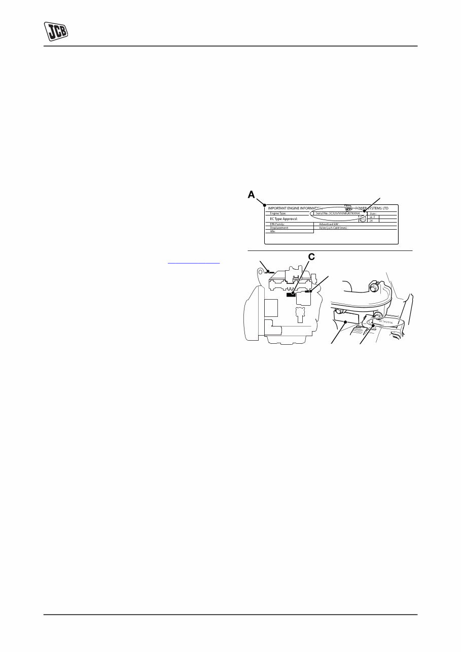
Section 1 - General Information Introduction Identifying your Machine 1-4 1-4 9803/9520-07 Typical Vehicle Identification Number 1 World Manufacturer Identification (SLP = JCB) 2 Machine Type (TM310, TM-W) 3 Year of Manufacture (1 = 2001, 2 = 2002, 3 = 2003, 4 = 2004, 5 = 2005, 6 = 2006, 7 = 2007) 4 Manufacturers Location (E = England) 5 Machine Serial Number (1314700) Component Identification Plates Typical Engine Identification Number T1-005_3 Engine data labels A are located on the cylinder block at position C and rocker cover D (if fitted). K Fig 4. ( T 1-4) . The data label contains important engine information and includes the engine identification number E. A typical engine identification number is explained as follows: 1 Engine Type S = 4.4 litre series. 2 Engine part number 3 Country of manufacture U = United Kingdom 4 Engine Serial Number 5 Year of Manufacture The last three parts of the engine identification number are stamped on the cylinder block at position B. C007820-C2 Fig 4. Engine 1 2 3 4 5 SLP TM310 3 E 1314700 SA 320/40001 U 00001 04 1 2 3 4 5 JCB Dieselmax (Tier 2) A = Naturally aspirated B = Turbocharged C = Turbocharged and intercooled JCB Dieselmax (Tier 3) D = Turbocharged E = Electronic common rail fuel injection F = Turbocharged and after-cooled U 00001 04 B C D B E
The JCB TM310 Telescopic Handler Service Manual is a comprehensive guide containing detailed information, diagrams, real photo illustrations, and schemes. It provides step-by-step operations for repair, servicing, technical maintenance, and troubleshooting procedures for your machine. Whether you are a professional mechanic or a DIY enthusiast, this manual equips you with the necessary information for machine repair and maintenance.
With 632 pages and a file size of 228Mb, this manual covers a wide range of topics including general information, care and safety, routine maintenance, electrics, hydraulics, transmission, brakes, engine, and network systems. The manual is available in English language and is suitable for JCB Telescopic Handler TM310 with all serial numbers.
One of the advantages of having this manual in digital format is the ability to use the search feature in Acrobat to quickly find the information you need. You can also print out specific pages or the entire manual as per your requirement.
If you are looking for other manuals for JCB machines, you can find them by clicking on the "Recipes / Manuals" section in the upper right corner. Feel free to reach out if you have any questions or if there's a specific manual you've been searching for. Have a great day!







 Lifetime Access




