Section 1 - General Information 1 - 0 1 - 0 9803/3630-14 Page left intentionally blank
Page No. Contents Section 1 - General Information 1 - i 1 - i Introduction About This Publication .............................................................................. 1 - 1 Machine Model and Serial Number ..................................................... 1 - 1 Using the Service Manual ................................................................... 1 - 1 Units of Measurement ......................................................................... 1 - 1 Section Numbering .............................................................................. 1 - 1 Left Side, Right Side ............................................................................ 1 - 2 Cross References ................................................................................ 1 - 2 Identifying Your Machine .......................................................................... 1 - 3 Machine Identification Plate ................................................................ 1 - 3 Component Identification Plates .......................................................... 1 - 4 Standard Torque Settings Zinc Plated Fasteners and Dacromet Fasteners ...................................... 1 - 6 Introduction .......................................................................................... 1 - 6 Bolts and Screws ................................................................................. 1 - 6 Hydraulic Connections ............................................................................ 1 - 10 'O' Ring Face Seal System ................................................................ 1 - 10 'Torque Stop' Hose System ............................................................... 1 - 13 Service Tools Numerical List ......................................................................................... 1 - 14 Tool Detail Reference ............................................................................. 1 - 18 Section B - Frame and Bodywork ...................................................... 1 - 18 Section C - Electrics .......................................................................... 1 - 22 Section E - Hydraulics ....................................................................... 1 - 24 Section F - Transmission ................................................................... 1 - 30 Section H - Steering .......................................................................... 1 - 32 Section K - Engine ............................................................................. 1 - 33 Service Consumables Sealing and Retaining Compounds ........................................................ 1 - 36 Terms and Definitions Colour Coding ......................................................................................... 1 - 37 Hydraulic Schematic Colour Codes ................................................... 1 - 37
Section 1 - General Information Page left intentionally blank 1 - ii 1 - ii
Section 1 - General Information 1 - 1 1 - 1 9803/3630-14 Introduction About This Publication Machine Model and Serial Number This publication provides information for the following models in the JCB product range: – 530-70 from S/N 768740 – 532-120 from S/N 774598 – 533-105 from S/N 786756 – 535-60 from S/N 1064599 – 535-95 from S/N 778295 – 535-125 from S/N 1064203 – 535-140 from S/N 1065087 – 537-135 (550) from S/N 774605 – 540-70 from S/N 771065 – 540-140 from S/N 1064723 – 540-170 (5508) from S/N 780925 Using the Service Manual T11-004 This publication is designed for the benefit of JCB Distributor Service Engineers who are receiving, or have received, training by JCB Technical Training Department. These personnel should have a sound knowledge of workshop practice, safety procedures, and general techniques associated with the maintenance and repair of hydraulic earthmoving equipment. The illustrations in this publication are for guidance only. Where the machines differ, the text and/or the illustration will specify. General warnings in Section 2 are repeated throughout the manual, as well as specific warnings. Read all safety statements regularly, so you do not forget them. Renewal of oil seals, gaskets, etc., and any component showing obvious signs of wear or damage is expected as a matter of course. It is expected that components will be cleaned and lubricated where appropriate, and that any opened hose or pipe connections will be blanked to prevent excessive loss of hydraulic fluid and ingress of dirt. Where a torque setting is given as a single figure it may be varied by plus or minus 3%. Torque figures indicated are for dry threads, hence for lubricated threads may be reduced by one third. The manufacturer's policy is one of continuous improvement. The right to change the specification of the machine without notice is reserved. No responsibility will be accepted for discrepancies which may occur between specifications of the machine and the descriptions contained in this publication. Finally, please remember above all else safety must come first! Units of Measurement T1-001_2 In this publication, the S.I. system of units is used. For example, liquid capacities are given in litres. The Imperial units follow in parentheses ( ) eg 28 litres (6 gal). Section Numbering T11-005 The manual is compiled in sections, the first three are numbered and contain information as follows: The remaining sections are alphabetically coded and deal with Dismantling, Overhaul etc. of specific components, for example: Section contents, technical data, circuit descriptions, operation descriptions etc. are inserted at the beginning of each alphabetically coded section. 1 General Information - includes torque settings and service tools. 2 Care and Safety - includes warnings and cautions pertinent to aspects of workshop procedures etc. 3 Maintenance - includes service schedules and recommended lubricants for all the machine. A Attachments B Body and Framework, etc.
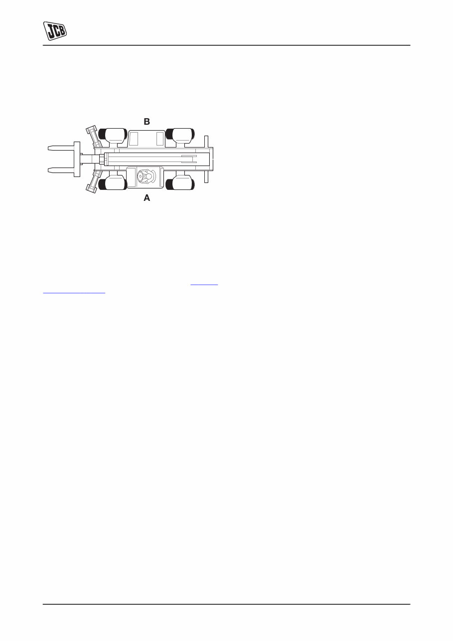
Section 1 - General Information Introduction About This Publication 1 - 2 1 - 2 9803/3630-14 Left Side, Right Side In this publication, `left' A and `right' B mean your left and right when you are seated correctly in the machine. Fig 1. Cross References T1-004_2 In this publication, page cross references are made by presenting the subject title printed in bold, italic and underlined. It is preceeded by the 'go to' symbol. The number of the page upon which the subject begins, is indicated within the brackets. For example: K Cross References ( T 1-2) .
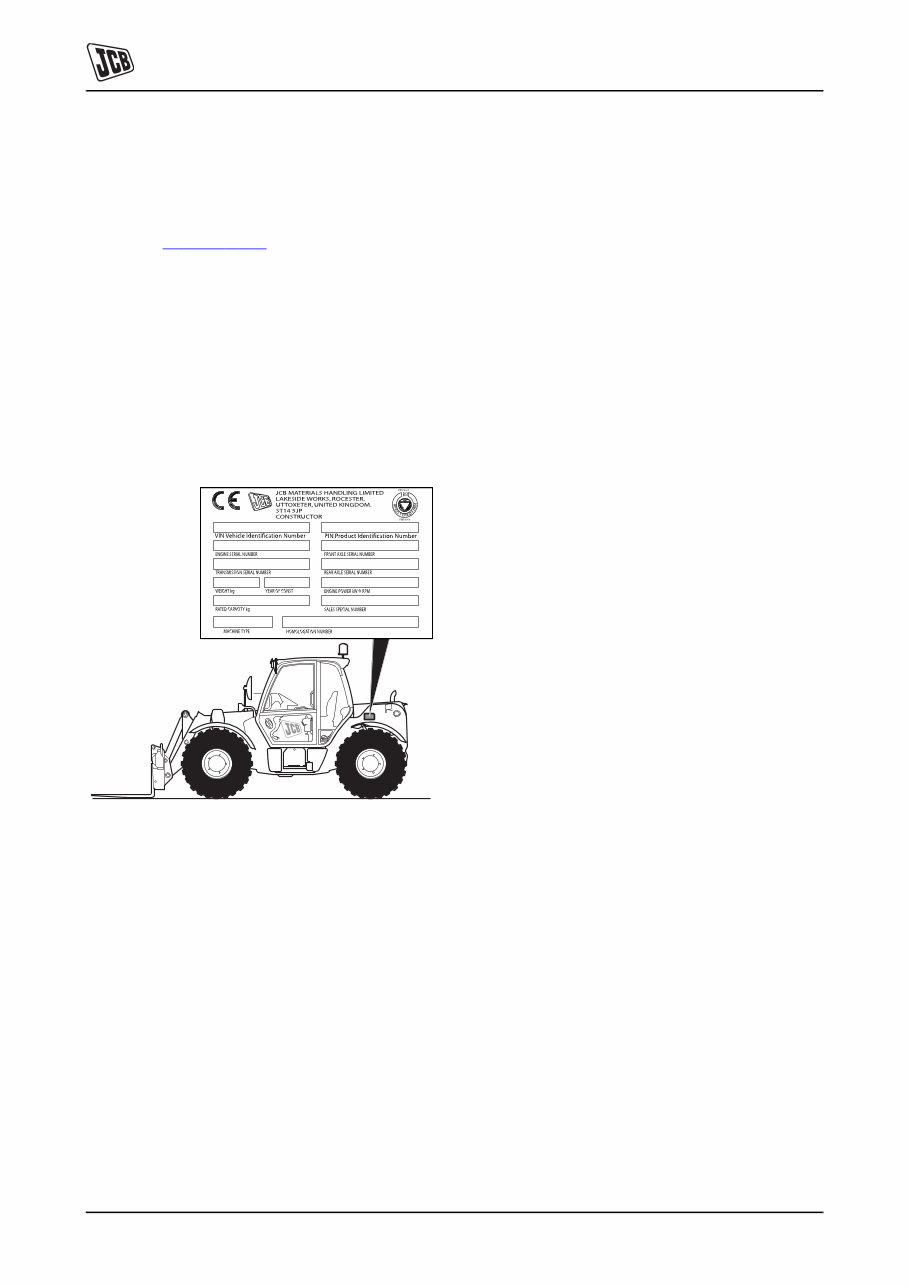
Section 1 - General Information Introduction Identifying Your Machine 1 - 3 1 - 3 9803/3630-14 Identifying Your Machine Machine Identification Plate Your machine has an identification plate mounted as shown, see K Fig 2. ( T 1-3) . The serial numbers of the machine and its major units are stamped on the plate. The serial number of each major unit is also stamped on the unit itself. If a major unit is replaced by a new one, the serial number on the identification plate will be wrong. Either stamp the new number of the unit on the identification plate, or simply stamp out the old number. This will prevent the wrong unit number being quoted when replacement parts are ordered. The machine and engine serial numbers can help identify exactly the type of equipment you have. Fig 2. Typical Vehicle Identification Number (VIN) 1 World Manufacturer Identification SLP = JCB 2 Year of Manufacture 3 Manufacturer Location E = England 4 Machine Serial Number 1 2 3 4 5 SLP 535 R E 0754001 P = 1993 V = 1997 1 = 2001 R = 1994 W = 1998 2 = 2002 S = 1995 X = 1999 3 = 2003 T = 1996 Y = 2000 4 = 2004
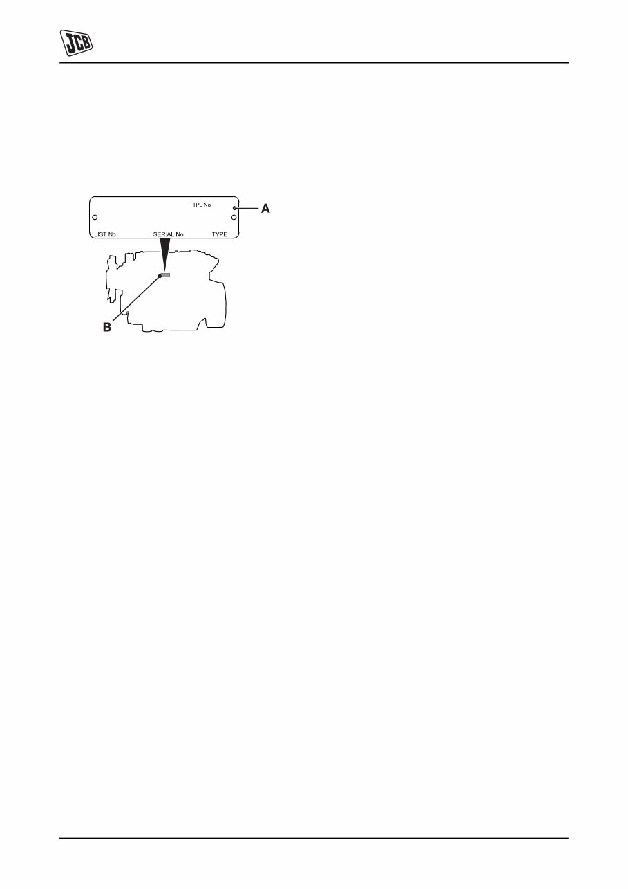
Section 1 - General Information Introduction Identifying Your Machine 1 - 4 1 - 4 9803/3630-14 Component Identification Plates Typical Engine Identification Number The engine serial number is stamped on label 3-A which is fastened to the right side of the cylinder block at 3-B, near the fuel filter. Fig 3. 1 Engine Type A series - low emission, stage 1 AK = 4 cylinder turbo AR = 4 cylinder naturally aspirated R series - low emission, stage 2 RE = 4 cylinder naturally aspirated RG = 4 cylinder turbo RJ = 4 cylinder air to air charge cooled 2 Build Number 3 Country of manufacture U = United Kingdom 4 Engine Serial Number 5 Year of Manufacture 1 2 3 4 5 RE 50261 U 500405 P
The JCB Loadall 530 532 533 535 Service & Repair Workshop Manual is a comprehensive resource for all your repair and servicing needs. Whether you are a professional mechanic or a DIY enthusiast, this manual provides detailed instructions and troubleshooting procedures to ensure the job is done correctly.
Containing hundreds of pages with detailed photos and diagrams, this professional manual is an invaluable tool for anyone working on JCB Loadall 530, 532, 533, and 535 models. You can easily print out a single page or the entire manual, and it can be accessed on multiple computers without any limitations or expiry dates.
Compatible with both Windows and MAC computers, this full manual is available for instant access on your computer, tablet, or smartphone. Say goodbye to renewal fees or trial periods – this manual is yours for life. Click the button to get your hands on this essential resource.







 Lifetime Access




