



Copyright © 2004 JCB SERVICE. All rights reserved. No part of this publication may be reproduced, stored in a retrieval system, or transmitted in any form or by any other means,
electronic, mechanical, photocopying or otherwise, without prior permission from JCB SERVICE.
World Class
Customer Support
9803/3630-14
Publication No.
Issued by JCB Technical Publications, JCB Aftermarket Training, Woodseat, Rocester, Staffordshire, ST14 5BW, England. Tel +44 1889 591300 Fax +44 1889 591400
Service Manual
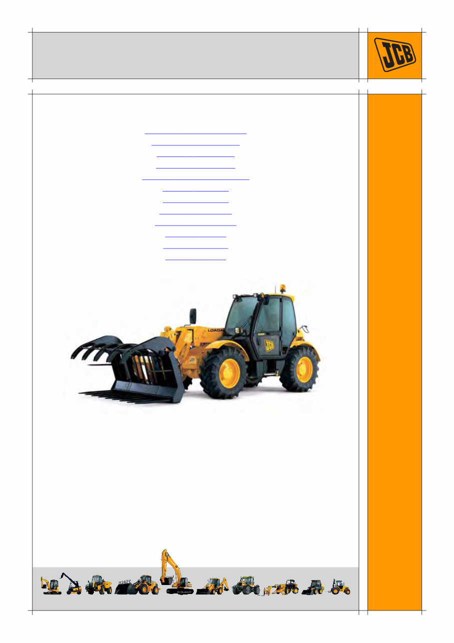
Side Engine Loadalls
Section 1 - General Information
Section 2 - Care and Safety
Section 3 - Maintenance
Section A - Attachments
Section B - Body and Framework
Section C - Electrics
Section D - Controls
Section E - Hydraulics
Section F - Transmission
Section G - Brakes
Section H - Steering
Section K - Engine

Section 0 - Service Manual
0 - 0 0 - 0
9803/3630-14
Page left intentionally blank
Copyright © 2004 JCB SERVICE. All rights reserved. No part of this publication may be reproduced, stored in a retrieval system, or transmitted in any form or by any other means,
electronic, mechanical, photocopying or otherwise, without prior permission from JCB SERVICE.
World Class
Customer Support
9803/3630-14
Publication No.
Issued by JCB Technical Publications, JCB Aftermarket Training, Woodseat, Rocester, Staffordshire, ST14 5BW, England. Tel +44 1889 591300 Fax +44 1889 591400
Section 1
General Information
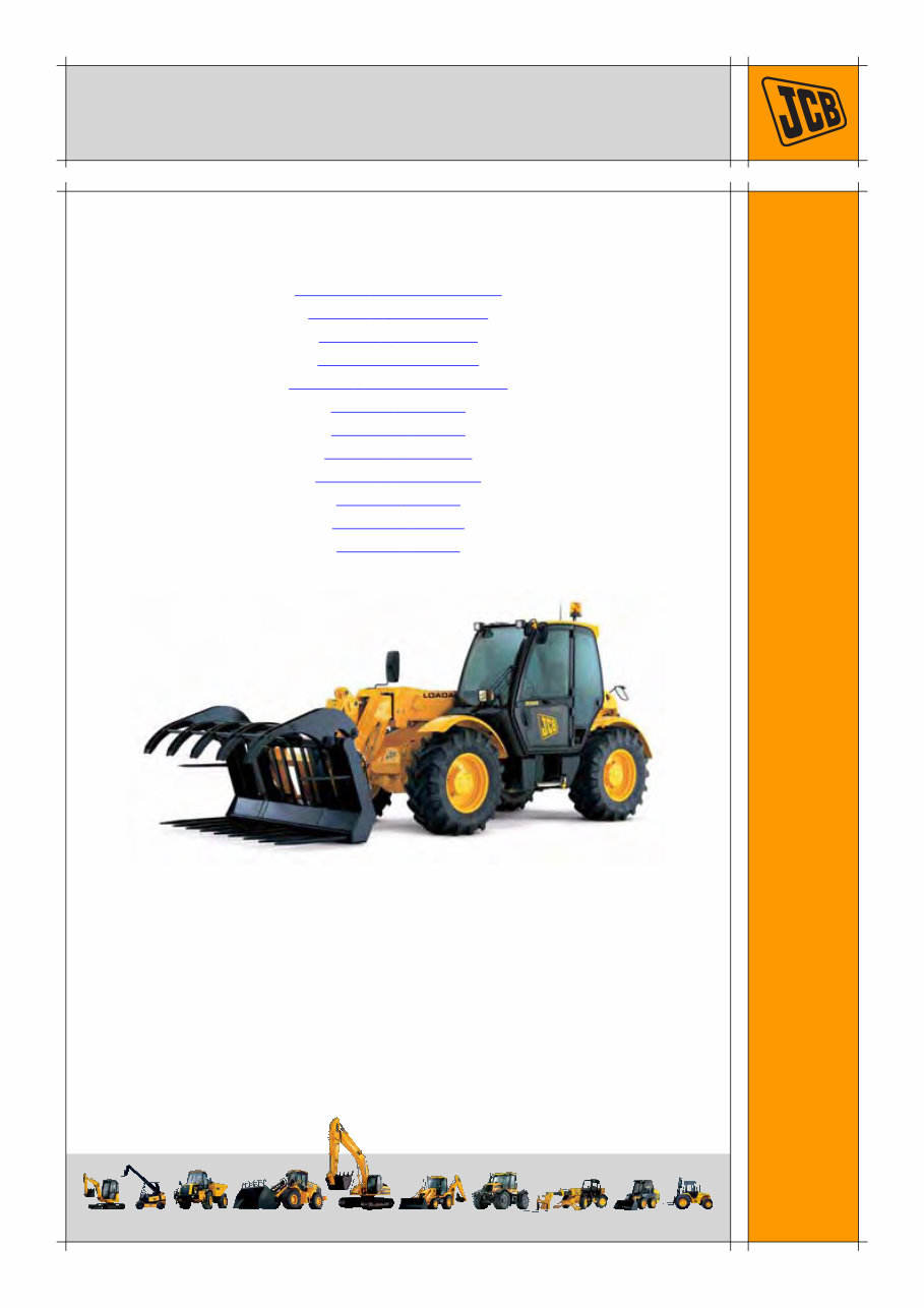
Service Manual - Side Engine Loadalls
Section 1 - General Information
Section 2 - Care and Safety
Section 3 - Maintenance
Section A - Attachments
Section B - Body and Framework
Section C - Electrics
Section D - Controls
Section E - Hydraulics
Section F - Transmission
Section G - Brakes
Section H - Steering
Section K - Engine

Section 1 - General Information
1 - 0 1 - 0
9803/3630-14
Page left intentionally blank

Page No. Contents
Section 1 - General Information
1 - i 1 - i
Introduction
About This Publication .............................................................................. 1 - 1
Machine Model and Serial Number ..................................................... 1 - 1
Using the Service Manual ................................................................... 1 - 1
Units of Measurement ......................................................................... 1 - 1
Section Numbering .............................................................................. 1 - 1
Left Side, Right Side ............................................................................ 1 - 2
Cross References ................................................................................ 1 - 2
Identifying Your Machine .......................................................................... 1 - 3
Machine Identification Plate ................................................................ 1 - 3
Component Identification Plates .......................................................... 1 - 4
Standard Torque Settings
Zinc Plated Fasteners and Dacromet Fasteners ...................................... 1 - 6
Introduction .......................................................................................... 1 - 6
Bolts and Screws ................................................................................. 1 - 6
Hydraulic Connections ............................................................................ 1 - 10
'O' Ring Face Seal System ................................................................ 1 - 10
'Torque Stop' Hose System ............................................................... 1 - 13
Service Tools
Numerical List ......................................................................................... 1 - 14
Tool Detail Reference ............................................................................. 1 - 18
Section B - Frame and Bodywork ...................................................... 1 - 18
Section C - Electrics .......................................................................... 1 - 22
Section E - Hydraulics ....................................................................... 1 - 24
Section F - Transmission ................................................................... 1 - 30
Section H - Steering .......................................................................... 1 - 32
Section K - Engine ............................................................................. 1 - 33
Service Consumables
Sealing and Retaining Compounds ........................................................ 1 - 36
Terms and Definitions
Colour Coding ......................................................................................... 1 - 37
Hydraulic Schematic Colour Codes ................................................... 1 - 37

Section 1 - General Information
Page left intentionally blank
1 - ii 1 - ii

Section 1 - General Information
1 - 1 1 - 1
9803/3630-14
Introduction
About This Publication
Machine Model and Serial Number
This publication provides information for the following
models in the JCB product range:
– 530-70 from S/N 768740
– 532-120 from S/N 774598
– 533-105 from S/N 786756
– 535-60 from S/N 1064599
– 535-95 from S/N 778295
– 535-125 from S/N 1064203
– 535-140 from S/N 1065087
– 537-135 (550) from S/N 774605
– 540-70 from S/N 771065
– 540-140 from S/N 1064723
– 540-170 (5508) from S/N 780925
Using the Service Manual
T11-004
This publication is designed for the benefit of JCB
Distributor Service Engineers who are receiving, or have
received, training by JCB Technical Training Department.
These personnel should have a sound knowledge of
workshop practice, safety procedures, and general
techniques associated with the maintenance and repair of
hydraulic earthmoving equipment.
The illustrations in this publication are for guidance only.
Where the machines differ, the text and/or the illustration
will specify.
General warnings in Section 2 are repeated throughout the
manual, as well as specific warnings. Read all safety
statements regularly, so you do not forget them.
Renewal of oil seals, gaskets, etc., and any component
showing obvious signs of wear or damage is expected as
a matter of course. It is expected that components will be
cleaned and lubricated where appropriate, and that any
opened hose or pipe connections will be blanked to
prevent excessive loss of hydraulic fluid and ingress of dirt.
Where a torque setting is given as a single figure it may be
varied by plus or minus 3%. Torque figures indicated are
for dry threads, hence for lubricated threads may be
reduced by one third.
The manufacturer's policy is one of continuous
improvement. The right to change the specification of the
machine without notice is reserved. No responsibility will
be accepted for discrepancies which may occur between
specifications of the machine and the descriptions
contained in this publication.
Finally, please remember above all else safety must come
first!
Units of Measurement
T1-001_2
In this publication, the S.I. system of units is used. For
example, liquid capacities are given in litres. The Imperial
units follow in parentheses ( ) eg 28 litres (6 gal).
Section Numbering
T11-005
The manual is compiled in sections, the first three are
numbered and contain information as follows:
The remaining sections are alphabetically coded and deal
with Dismantling, Overhaul etc. of specific components, for
example:
Section contents, technical data, circuit descriptions,
operation descriptions etc. are inserted at the beginning of
each alphabetically coded section.
1 General Information - includes torque settings and
service tools.
2 Care and Safety - includes warnings and cautions
pertinent to aspects of workshop procedures etc.
3 Maintenance - includes service schedules and
recommended lubricants for all the machine.
A Attachments
B Body and Framework, etc.
Section 1 - General Information
Introduction
About This Publication
1 - 2 1 - 2
9803/3630-14
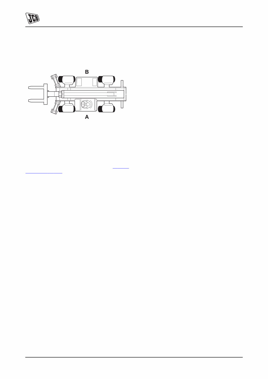
Left Side, Right Side
In this publication, `left' A and `right' B mean your left and
right when you are seated correctly in the machine.
Fig 1.
Cross References
T1-004_2
In this publication, page cross references are made by
presenting the subject title printed in bold, italic and
underlined. It is preceeded by the 'go to' symbol. The
number of the page upon which the subject begins, is
indicated within the brackets. For example: K Cross
References ( T 1-2) .
Section 1 - General Information
Introduction
Identifying Your Machine
1 - 3 1 - 3
9803/3630-14
Identifying Your Machine
Machine Identification Plate
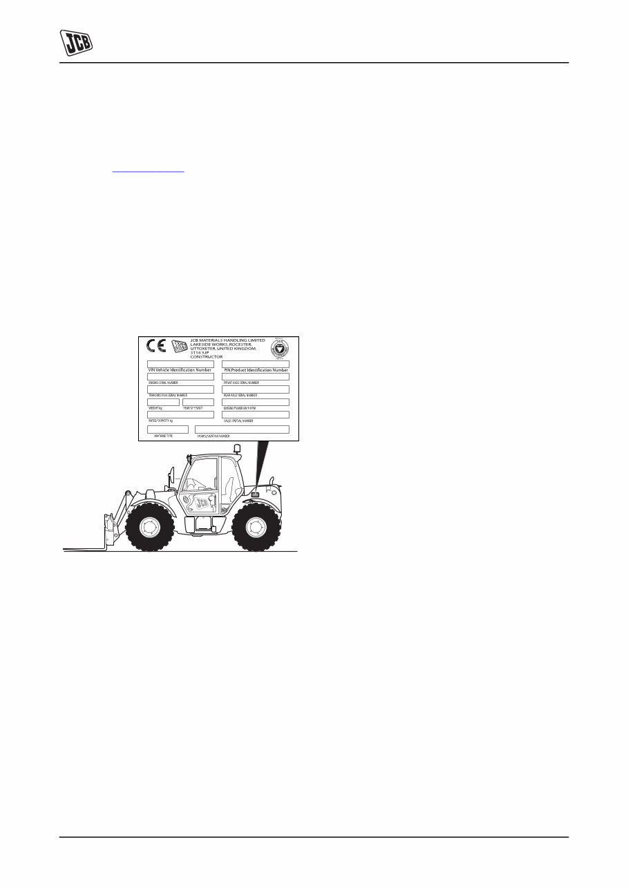
Your machine has an identification plate mounted as
shown, see K Fig 2. ( T 1-3) . The serial numbers of the
machine and its major units are stamped on the plate.
The serial number of each major unit is also stamped on
the unit itself. If a major unit is replaced by a new one, the
serial number on the identification plate will be wrong.
Either stamp the new number of the unit on the
identification plate, or simply stamp out the old number.
This will prevent the wrong unit number being quoted when
replacement parts are ordered.
The machine and engine serial numbers can help identify
exactly the type of equipment you have.
Fig 2.
Typical Vehicle Identification Number (VIN)
1 World Manufacturer Identification
SLP = JCB
2 Year of Manufacture
3 Manufacturer Location
E = England
4 Machine Serial Number
1 2 3 4 5
SLP 535 R E 0754001
P = 1993 V = 1997 1 = 2001
R = 1994 W = 1998 2 = 2002
S = 1995 X = 1999 3 = 2003
T = 1996 Y = 2000 4 = 2004
Section 1 - General Information
Introduction
Identifying Your Machine
1 - 4 1 - 4
9803/3630-14
Component Identification Plates
Typical Engine Identification Number
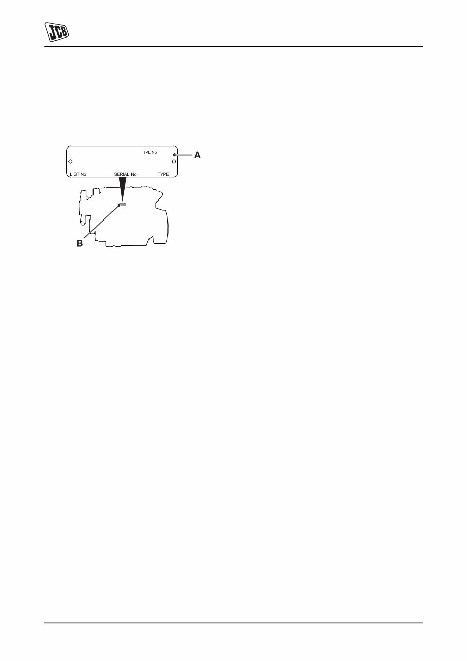
The engine serial number is stamped on label 3-A which is
fastened to the right side of the cylinder block at 3-B, near
the fuel filter.
Fig 3.
1 Engine Type
A series - low emission, stage 1
AK = 4 cylinder turbo
AR = 4 cylinder naturally aspirated
R series - low emission, stage 2
RE = 4 cylinder naturally aspirated
RG = 4 cylinder turbo
RJ = 4 cylinder air to air charge cooled
2 Build Number
3 Country of manufacture
U = United Kingdom
4 Engine Serial Number
5 Year of Manufacture
1 2 3 4 5
RE 50261 U 500405 P
You're Reading a Preview
What's Included?
 Lifetime Access
Fast Download Speeds
Online & Offline Access
Access PDF Contents & Bookmarks
Full Search Facility
Print one or all pages of your manual
$31.99
JCB Loadall 530 532 533 535 537 540 Telescopic Handler Service Repair Workshop Manual
Viewed 78 Times Today

What's Included?
Lifetime Access
Fast Download Speeds
Online & Offline Access
Access PDF Contents & Bookmarks
Full Search Facility
Print one or all pages of your manual
$31.99

Secure transaction
What's Included?
Lifetime Access
Fast Download Speeds
Online & Offline Access
Access PDF Contents & Bookmarks
Full Search Facility
Print one or all pages of your manual
Description
This manual is suitable for individuals ranging from first-time owners to professional technicians. It is designed in an easy-to-read format and provides comprehensive information necessary for accurate procedure execution. Keeping this service manual accessible and referring to it regularly is recommended. Adhering to routine and preventive maintenance outlined in the manual will result in time and cost savings by preventing premature failure and unnecessary repairs.
- Models Covered:
- 530-70 from S/N 768740
- 532-120 from S/N 774598
- 533-105 from S/N 786756
- 535-60 from S/N 1064599
- 535-95 from S/N 778295
- 535-125 from S/N 1064203
- 535-140 from S/N 1065087
- 537-135 (550) from S/N 774605
- 540-70 from S/N 771065
- 540-140 from S/N 1064723
- 540-170 (5508) from S/N 780925
- Service Repair Manual Covers:
- Section 1 - General Information
- Section 2 - Care and Safety
- Section 3 - Maintenance
- Section A - Attachments
- Section B - Body and Framework
- Section C - Electrics
- Section D - Controls
- Section E - Hydraulics
- Section F - Transmission
- Section G - Brakes
- Section H - Steering
- Section K - Engine
File Format: PDF
Compatible: All Versions of Windows & Mac
Language: English
Requirements: Adobe Reader & Win


