

JCB 525-50 loadall telehandler service and repair manual
What's Included?
Fast Download Speeds
Online & Offline Access
Access PDF Contents & Bookmarks
Full Search Facility
Print one or all pages of your manual

General Information 1
Care & Safety 2
Routine Maintenance 3
Attachments A
Body & Framework B
Electrics C
Controls D
Hydraulics E
Transmission F
Brakes G
Steering H
Engine K
R
Service
Manual
Loadall
Models:
520-50
from Serial No. 754001
525-50
from Serial No. 789308
525-50S
from Serial No. 1037581
PUBLISHED BY THE
TECHNICAL PUBLICATIONS DEPARTMENT
OF JCB SERVICE; ©
WORLD PARTS CENTRE, WATERLOO
PARK, UTTOXETER,
ST14 5PA, ENGLAND
Tel. 01889 - 590312
PRINTED IN ENGLAND
Publication No. 9803/3620 Issue 9


Introduction
This publication is designed for the benefit of JCB Distributor Service Engineers who are receiving, or have received, training
by JCB Technical Training Department.
These personnel should have a sound knowledge of workshop practice, safety procedures, and general techniques associated
with the maintenance and repair of hydraulic earthmoving equipment.
Renewal of oil seals, gaskets, etc., and any component showing obvious signs of wear or damage is expected as a matter of
course. It is expected that components will be cleaned and lubricated where appropriate, and that any opened hose or pipe
connections will be blanked to prevent excessive loss of hydraulic fluid and ingress of dirt. Finally, please remember above all
else SAFETY MUST COME FIRST!
The manual is compiled in sections, the first three are numbered and contain information as follows:
1 = General Information - includes torque settings and service tools.
2 = Care & Safety - includes warnings and cautions pertinent to aspects of workshop procedures etc.
3 = Routine Maintenance - includes service schedules and recommended lubricants for all the machine.
The remaining sections are alphabetically coded and deal with Dismantling, Overhaul etc. of specific components, for
example:
A = Attachments
B = Body & Framework ...etc.
The page numbering in each alphabetically coded section is not continuous. This allows for the insertion of new items in later
issues of the manual.
Section contents, technical data, circuit descriptions, operation descriptions etc are inserted at the beginning of each
alphabetically coded section.
READ the section contents to locate machine types, machine type indentification IS NOT listed on individual pages.
All sections are listed on the front cover; tabbed divider cards align directly with individual sections on the front cover for rapid
reference.
Where a torque setting is given as a single figure it may be varied by plus or minus 3%. Torque figures indicated are for dry
threads, hence for lubricated threads may be reduced by one third.
'Left Hand' and 'Right Hand' are as viewed from the rear of the machine facing forwards.
This Service Manual covers the following machines:
520-50 (520 N. Am.) - from Machine Serial Number 754001
525-50 - from Machine Serial Number 789308
525-50S - from Machine Serial Number 1037581
9803/3620 Issue 5*


i
Section 1 General Information
9803/3620
Section 1
i
Issue 2*
Contents Page No.
Identification 1 - 1
Torque Settings 2 - 1
Service Tools
- Numerical List 3 - 1
- Section C 4 - 1
- Section E 5 - 1
- Section F 6 - 1
- Section H 7 - 1
- Section K 7 - 1
Sealing and Retaining Compounds 8 - 1
1 - 1
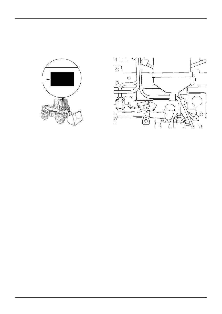
Identification Plate
Your machine has an identification plate V mounted as
shown. The serial numbers of the machine and its major
units are stamped on the plate.
Explanation of Vehicle Identification Number (VIN)
SLP52050RE0754001
A B C D E
A World Manufacturer Identification SLP = JCB
B Machine Model 520-50
C Year of Manufacture S
P = 1993 V = 1997 1 = 2001
R = 1994 W = 1998 2 = 2002
S = 1995 X = 1999 3 = 2003
T = 1996 Y = 2000 4 = 2004
D Manufacturing Location E = England
E Machine Serial Number 0754001
Machine Model Explanation
520 - 50
FG H
F 500 Series machine range
G 2.0 tonnes lift capacity
H 5.0 metres lift height
The serial number of each major unit is also stamped on the
unit itself. If a major unit is replaced by a new one, the serial
number on the identification plate will be wrong. Either
stamp the new number of the unit on the identification plate,
or simply stamp out the old number. This will prevent the
wrong unit number being quoted when replacement parts
are ordered.
The machine and engine serial numbers can help identify
exactly the type of equipment you have.
General Information
9803/3620
1 - 1
Issue 4*
Section 1 Section 1
Unit Identification
The engine serial number is stamped on label W which is
fastened to the right side of the cylinder block, near the fuel
filter.
Explanation of Engine Identification Number
AA 50261 U 500405 P
A B C D E
A Engine Type:
A series
AK = 4 cylinder turbo - low emission, stage 1
AR = 4 cylinder naturally aspirated - low
emission, stage 1
R Series
RE = 4 cylinder naturally aspirated, low
emission, stage 2
RG = 4 cylinder turbo, low emission stage 2
RJ = 4 cylinder air to air charge cooled, low
emission, stage 2
B Build Number
C Country of Manufacture
D Engine Serial Number
E Year of Manufacture
If service information or parts are required, the complete
engine number should be quoted.
If there is also a number marked ‘TPL No’, this should be
quoted also.
If a short engine has been fitted in service, two engine serial
numbers and a TPL No. are stamped on the serial number
plate as at Z. All the numbers should be quoted when
requiring parts or information.
Note: Where the procedures in this manual differ according
to engine types, the text and/or illustrations will specify
which engine types apply.
Transmission and axle identification is shown on the next
page.
W
S181760
V
430250
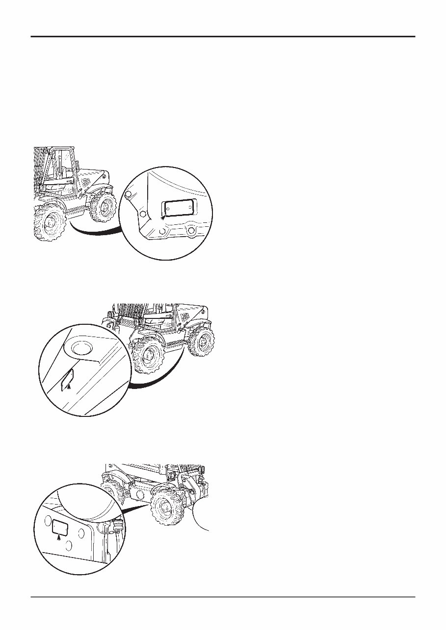
The Transmission serial number is stamped on label Y which
is mounted on the rear face.
The rear axle serial number is stamped on plate X mounted
to the front face of the axle.
The front axle serial number is stamped on plate Z mounted
on the rear face of the arm.
1 - 2
Section 1 General Information
9803/3620
Section 1
1 - 2
Issue 1
X
S241310
S241320
S241330
Y
Z

2 - 1
Section 1 General Information
9803/3620
Section 1
2 - 1
Issue 1
Torque Settings
Use only where no torque setting is specified in the text. Values are for dry threads and may be within three per cent of the
figures stated. For lubricated threads the values should be REDUCED by one third.
UNF Grade 'S' Bolts
Bolt Size Hexagon (A/F) Torque Settings
in (mm) in Nm kgf m lbf ft
1
/4 (6.3)
7
/16 14 1.4 10
5
/16 (7.9)
1
/2 28 2.8 20
3
/8 (9.5)
9
/16 49 5.0 36
7
/16 (11.1)
5
/8 78 8.0 58
1
/2 (12.7)
3
/4 117 12.0 87
9
/16 (14.3)
13
/16 170 17.3 125
5
/8 (15.9)
15
/16 238 24.3 175
3
/4 (19.0) 1
1
/8 407 41.5 300
7
/8 (22.2) 1
5
/16 650 66.3 480
1 (25.4) 1
1
/2 970 99.0 715
1
1
/4 (31.7) 1
7
/8 1940 198.0 1430
1
1
/2 (38.1) 2
1
/4 3390 345.0 2500
Metric Grade 8.8 Bolts
Bolt Size Hexagon (A/F) Torque Settings
(mm) mm Nm kgf m lbf ft
M5 (5) 8 7 0.7 5
M6 (6) 10 12 1.2 9
M8 (8) 13 28 3.0 21
M10 (10) 17 56 5.7 42
M12 (12) 19 98 10 72
M16 (16) 24 244 25 180
M20 (20) 30 476 48 352
M24 (24) 36 822 84 607
M30 (30) 46 1633 166 1205
M36 (36) 55 2854 291 2105
Rivet Nut Bolts/Screws
Bolt Size Torque Settings (for steel rivet nuts)
(mm) Nm kgf m lbf ft
M3 (3) 1.2 0.12 0.9
M4 (4) 3.0 0.3 2.0
M5 (5) 6.0 0.6 4.5
M6 (6) 10.0 1.0 7.5
M8 (8) 24.0 2.5 18.0
M10 (10) 48.0 4.9 35.5
M12 (12) 82.0 8.4 60.5
Note: All bolts used on JCB machines are high tensile and must not be replaced by bolts of a lesser tensile specification.

3 - 1
Service Tools
Numerical List Page No
1406/0011 Bonded Washer 5-1
1406/0014 Bonded Washer 5-1
1406/0021 Bonded Washer 5-1
1406/0029 Bonded Washer 5-1
1604/0003 Adapter 5-3
1604/0004 Adapter 5-3
1604/0006 Adapter 5-1
1606/0003 Adapter 5-3
1606/0004 Adapter 5-3
1606/0007 Adapter 5-3
1606/0008 Adapter 5-3
1606/0009 Adapter 5-3
1606/0012 Adapter 5-3
1606/0014 Adapter 5-3
1606/0015 Adapter 5-3
1606/0017 Adapter 5-3
1612/0006 Adapter 5-1
4101/0251 Threadlocker and Sealer 8-1
4101/0451 Threadlocker 8-1
4101/0552 Threadlocker and Sealer (High Strength) 8-1
4101/0651 Retainer (High Strength) 8-1
4102/0551 High Strength Threadlocker 8-1
4102/1201 Multi-Gasket 8-1
4102/1951 Threadseal 8-1
4104/0251 Activator (Aerosol) 8-1
4104/0253 Activator (Bottle) 8-1
4104/1557 Cleaner/Degreaser 8-1
816/00189 Blanking Cap 5-2
816/00190 Blanking Cap 5-2
816/00193 Blanking Cap 5-2
816/00196 Blanking Cap 5-2
816/00197 Blanking Cap 5-2
816/00294 Blanking Cap 5-2
816/15118 Pressure Test Adapter 5-3
816/20008 Adapter 5-1
816/55038 Pressure Test Adapter 5-1
816/55040 Pressure Test Adapter 5-1
816/50043 'T' Adapter 5-2
892/00039 Spool Clamp 5-2
892/00041 De-glazing Tool 7-1
892/00047 'T' Adapter 5-2
892/00048 'T' Adapter 5-2
892/00049 'T' Adapter 5-2
892/00051 'T' Adapter 5-2
892/00055 Blanking Plug 5-2
892/00056 Blanking Plug 5-2
892/00057 Blanking Plug 5-2
892/00058 Blanking Plug 5-2
892/00059 Blanking Plug 5-2
892/00060 Blanking Plug 5-2
892/00071 Adapter 5-3
892/00074 Female Connector 5-2
892/00075 Female Connector 5-2
892/00076 Female Connector 5-2
892/00077 Female Connector 5-2
892/00121 Discharge Tester 4-1
892/00137 Micro-Bore Hose 5-3
892/00179 Bearing Press 6-1
892/00180 Seal Fitting Tool 7-1
892/00181 Plastic Boss 7-1
Page No
892/00223 Hand Pump 5-3
892/00225 Adapter - Impulse Extractor 6-2
892/00253 Pressure Test Kit 5-1
892/00255
1
/4'' BSP Test Point 5-3
892/00256
3
/8'' BSP Test Point 5-3
892/00257
1
/2'' BSP Test Point 5-3
892/00258
5
/8'' BSP Test Point 5-3
892/00259 1'' BSP Test Point 5-3
892/00260 1
1
/4'' BSP Test Point 5-3
892/00261
5
/8'' UNF Test Point 5-3
892/00262
1
/4'' M BSP 1/4'' F BSP 5-1
892/00263
5
/8'' M BSP 5/8'' F BSP 5-1
892/00264
3
/4'' M BSP 3/4'' F BSP 5-1
892/00265 1'' M BSP 1'' F BSP 5-1
892/00268 Flow Monitoring Unit 5-1
892/00269 Sensor Head 5-1
892/00270 Load Valve 5-1
892/00271 Adapter 5-1
892/00272 Adapter 5-1
892/00274 Adapter 5-3
892/00275 Adapter 5-1
892/00276 Adapter 5-1
892/00277 Adapter 5-1
892/00279 Gauge 5-3
892/00281 AVO Meter 4-1
892/00282 Shunt 4-1
892/00283 Tool Kit Case 4-1
892/00284 Digital Tachometer 4-1
892/00285 Hyd. Oil Temperature Probe 4-1
892/00286 Surface Temperature Probe 4-1
892/00295 End Float Setting Tool 6-1
892/00301 Flow Test Adapter 6-1
892/00302 Flow Test Adapter 6-1
892/00304 Flow Test Adapter 6-1
892/00333 Heavy Duty Socket 6-2
892/00706 Test Probe 5-3
892/00817 Heavy Duty Socket 6-2
892/00818 Heavy Duty Socket 6-2
892/00819 Heavy Duty Socket 6-2
892/00836 Lifting Wire Assembly 7-2
892/00891 Seal Fitting Adaptor 6-2
892/00923 Test Block for ARV 5-3
892/00936 Timing Pin 7-2
892/01054 Compression Adaptor 7-2
892/01111 Rocker Assembly Tool 7-2
892/01112 Timing Case Alignment Tool 7-2
892/01113 Thermostat Fitting & Removal Tool 7-2
892/01114 Camshaft Gear Timing Pin 7-2
892/01115 Crankshaft Timing Pin 7-2
992/02800 ARV Extractor 5-2
992/04000 Torque Multiplier 6-2
992/04800 Drive Coupling Spanner 6-1
992/07603 Replacer- Bearing Cup 6-1
992/07608 Bearing Adapter 6-1
992/07609 Bearing Adapter 6-1
992/07610 Bearing Adapter 6-1
992/07611 Bearing Adapter 6-1
992/07612 Bearing Adapter 6-1
992/07613 Bearing Adapter 6-1
Section 1 General Information
9803/3620
Section 1
3 - 1
Issue 4*
*

3 - 2
Service Tools (cont'd)
Numerical List Page No
992/09500 Spanner 5-2
992/09700 Spanner 5-2
992/10100 Spool Clamp 5-2
992/10900 Test Harness for S.L.I 4-1
993/59300 2/4 Wheel Pressure Tester & Clamp 6-2
993/59500 Adapter - Impulse Extractor 6-2
993/99412 Adaptor Harness 4-1
The following parts are replacement items for kits and would
normally be included in the kit numbers above.
Replacement item for kit no. 892/00180
892/00181 Replacement Boss 7-1
Replacement item for kit no. 892/00253
892/00201 Replacement Gauge 5-1
892/00202 Replacement Gauge 5-1
892/00203 Replacement Gauge 5-1
892/00254 Replacement Hose 5-1
Section 1 General Information
9803/3620
Section 1
3 - 2
Issue 2*
*
You're Reading a Preview
What's Included?
Fast Download Speeds
Online & Offline Access
Access PDF Contents & Bookmarks
Full Search Facility
Print one or all pages of your manual
$36.99
Viewed 20 Times Today


Secure transaction
What's Included?
Fast Download Speeds
Online & Offline Access
Access PDF Contents & Bookmarks
Full Search Facility
Print one or all pages of your manual
$36.99
Official service manual for the JCB 525-50 series loadall telehandler forklifts. This manual covers the 525-50, 525-50 farm special, and 525-50 Military spec sheets.
- Includes detailed information on carburettor kits, oil filters, pistons, gaskets, brakes, sprockets, chains, wheel bearings, tires, lamps, bulbs, guards, gearbox, throttle, handlebar, seat, rack, start, kill, switch, button, fuel tank, rings, steering, electrical, suspension, exhaust, body, muffler, drive train, con rod, filter, spark plug, radiator, starter, stator, water pump, thermostat, intake, head, cams, clutch, cv joint, drive belt, transfer case, chain, sprocket, hub, differential, pegs, cover, skid plate, decals, oil tank, scoop, track, hydraulic, ram, bucket, arm, swivel, rubber, hose, union, gasket, hydraulic hoses, fittings, motors, pumps, valves, actuators, digging buckets, batteries, filters, engines, slew rings, spool valves, controls, pipes, rams, panels, seal kits, 2nd-user machines, transmissions, couplings, oils, parts manuals, bearings, fuses, grease nipples, work wear, bucket teeth, track repair links, bolts, and mini sprocket.
- Bookmarked chapters for easy navigation to identify exact repair service procedures quickly.
- Notes, cautions, and warnings throughout each chapter pinpoint critical service information.
- Numbered instructions guide you through every repair procedure in a step-by-step fashion.
- Bold figured numbers help you quickly match illustrations with instructions.
- Detailed illustrations, exploded diagrams, drawings, and photos guide you through every service repair procedure.
- Numbered table of contents for easy and fast information retrieval.
Manual Language: English
File Format: .PDF
File Delivery: Instant
Pages: 290
To purchase this repair manual, click on the green instant button at the upper left-hand corner of this page. After purchasing, download it to your computer to save and print pages whenever needed.


