Introduction This publication is designed for the benefit of JCB Distributor Service Engineers who are receiving, or have received, training by JCB International Training Centre. These personnel should have a sound knowledge of workshop practice, safety procedures, and general techniques associated with the maintenance and repair of hydraulic earthmoving equipment. Renewal of oil seals, gaskets, etc., and any component showing obvious signs of wear or damage is expected as a matter of course. It is expected that components will be cleaned and lubricated where appropriate, and that any opened hose or pipe connections will be blanked to prevent excessive loss of hydraulic fluid and ingress of dirt. Finally, please remember above all else SAFETY MUST COME FIRST! How to use this manual The manual is compiled in sections, the first three are numbered and contain information as follows: 1 = General Information - includes torque settings and service tools. 2 = Care & Safety - includes warnings and cautions pertinent to aspects of workshop procedures etc. 3 = Routine Maintenance - includes service schedules and recommended lubricants for all the machine. The remaining sections are alphabetically coded and deal with Dismantling, Overhaul etc. of specific components, for example: A = Attachments B = Body & Framework ...etc. The page numbering in each alphabetically coded section is not continuous. This allows for the insertion of new items in later issues of the manual. Section contents, technical data, circuit descriptions, operation descriptions etc are inserted at the beginning of each alphabetically coded section. READ the section contents to locate machine types, machine type identification IS NOT listed on individual pages. All sections are listed on the title page; tabbed divider cards align directly with individual sections on the front cover for rapid reference. Where a torque setting is given as a single figure it may be varied by plus or minus 3%. Torque figures indicated are for dry threads, hence for lubricated threads may be reduced by one third. 'Left Hand' and 'Right Hand' are as viewed from the rear of the machine facing forwards. This Service Manual covers the following machines, from Serial Number 277001 520-55 RS (Rear Steering) Farm Special & Construction 520-55 AWS (All Wheel Steering) Farm Special & Construction 526-55 Farm Special & Construction 526-55 AWS (All Wheel Steering) Farm Special & Construction 526S AWS (All Wheel Steering) Farm Special & Construction 9803/3695 Issue 5* *
Description The machine incorporated twin brake pedals to operate an independent brake circuit controlling each of the front wheels. This allowed single wheel braking to reduce the turning circle. The pedals could be locked together for road use. The machine was also equipped with manually selectable 2/4-wheel drive. The machine was fitted with permanent four wheel steering and four-wheel braking. Introduced as a development of the 520- 55 with a stronger inner boom and larger lift, tilt and displacement rams. The machine was fitted with JCB manufactured axles and drop box, and incorporated four-wheel power brakes. The machine was equipped with three manually selectable steering modes and an optional turbo-charged engine was available. 520-55 and 526-55 machines re-named 520 and 526. These machines incorporated a revised hydraulic tank, plastic fuel tank, fenders and engine cover. The 526 and 526S machine incorporated a longer wheelbase to allow for 24in. wheels and tyres on the 526S machine only. Drop box fitted with helical gears from axle serial number 453/275/00005. Introduced as a 90 hp turbo-charged engine version of the 520 machine. The stronger inner boom on the 526 was introduced to cope with the increased engine power. 9803/3630 Issue 1 Machine History Date 1993 Serial No. 277001 1994 Serial No. 277386 278610 1994 Serial No. 277468 1996 Serial No. 278967 1996 Serial No. 279289 280300 280577 1996 Serial No. 279598 Machine 520-55 RS (277001 - 279114) Machine introduction 520-55 AWS (504B N.Am) (277386 - 278966) Machine introduction JCB axles, drop box and 4 wheel power brakes fitted. 526-55 (277467 - 278966) Machine introduction 520 & 526 520 (278967 onwards) 526 (278967 - 279567) Machine introduction 526, 526S (526 Am.N) (279289 onwards) Machine introduction ECU controlled powershift available as an option. Single lever control and trailer braking. Power brakes replaced by inboard, front axle brakes. ECU control was replaced by relay controlled transmission. 520S (279598 onwards) Machine introduction
i Section 1 General Information 9803/3610 Section 1 i Issue 2* Contents Page No. Identification 1 - 1 Torque Settings 2 - 1 Service Tools - Numerical List 3 - 1 - Section B 3 - 3 - Section C 4 - 1 - Section E 5 - 1 - Section F 6 - 1 - Section H 7 - 1 - Section K 7 - 1 Sealing and Retaining Compounds 8 - 1 *
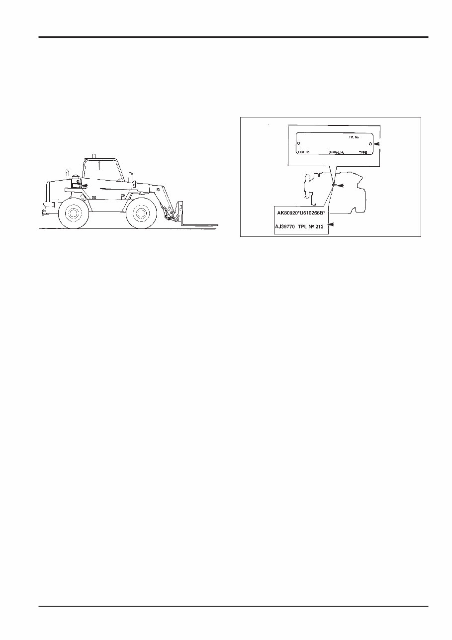
1 - 1 Identification Plate Your machine has an identification plate V mounted as shown. The serial numbers of the machine and its major units are stamped on the plate. Explanation of Vehicle Identification Number (VIN) SLP52655RE0277001 A B C D E A World Manufacturer Identification SLP = JCB B Machine Model 526-55 C Year of Manufacture S P = 1993 V = 1997 1 = 2001 R = 1994 W = 1998 2 = 2002 S = 1995 X = 1999 3 = 2003 T = 1996 Y = 2000 4 = 2004 D Manufacturing Location E = England E Machine Serial Number 0277001 Machine Model Explanation 526 - 55 FG H F 500 Series machine range G 2.6 tonnes lift capacity H 5.5 meters lift height With the introduction of the longer wheel base machine the lift height has been deleted from the serial number. 526 FG F 500 Series machine range G 2.6 tonnes lift capacity General Information 9803/3610 1 - 1 Issue 4* Section 1 Section 1 V S195340 Unit Identification The engine serial number is stamped on label W which is fastened to the right side of the cylinder block at Y, near the fuel filter. Explanation of Engine Identification Number Typical Engine Identification Number AA 50261 U 500405 P A B C D E A Engine Type: A series AA = 4 cylinder naturally aspirated AB = 4 cylinder turbo AK = 4 cylinder turbo - low emission, stage 1 AR = 4 cylinder naturally aspirated - low emission, stage 1 R Series RE = 4 cylinder naturally aspirated, low emission, stage 2 RG = 4 cylinder turbo, low emission stage 2 B Build Number C Country of Manufacture D Engine Serial Number E Year of Manufacture If service information or parts are required, the complete engine number should be quoted. If there is also a number marked ‘TPL No’, this should be quoted also. If a short engine has been fitted in service, two engine serial numbers and a TPL No. are stamped on the serial number plate as at Z. All the numbers should be quoted when requiring parts or information. Note: Where the procedures in this service manual differ according to engine types, the text and/or illustrations will specify which engine types apply. Transmission and axle identification is shown on the next page. Y W Z * *
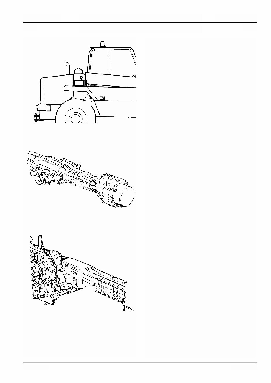
1 - 2 Section 1 General Information 9803/3610 Section 1 1 - 2 Issue 2 The Syncro Shuttle serial number is stamped on label Y as shown. The rear axle serial number is stamped on plate X as shown. The front axle serial number is stamped on plate Z as shown. X S196280 Z S196290 Y S088470
2 - 1 Section 1 General Information 9803/3610 Section 1 2 - 1 Issue 2* Torque Settings Use only where no torque setting is specified in the text. Values are for dry threads and may be within three per cent of the figures stated. For lubricated threads the values should be REDUCED by one third. UNF Grade 'S' Bolts Bolt Size Hexagon (A/F) Torque Settings in (mm) in Nm kgf m lbf ft 1 /4 (6.3) 7 /16 14 1.4 10 5 /16 (7.9) 1 /2 28 2.8 20 3 /8 (9.5) 9 /16 49 5.0 36 7 /16 (11.1) 5 /8 78 8.0 58 1 /2 (12.7) 3 /4 117 12.0 87 9 /16 (14.3) 13 /16 170 17.3 125 5 /8 (15.9) 15 /16 238 24.3 175 3 /4 (19.0) 1 1 /8 407 41.5 300 7 /8 (22.2) 1 5 /16 650 66.3 480 1 (25.4) 1 1 /2 970 99.0 715 1 1 /4 (31.7) 1 7 /8 1940 198.0 1430 1 1 /2 (38.1) 2 1 /4 3390 345.0 2500 Metric Grade 8.8 Bolts Bolt Size Hexagon (A/F) Torque Settings (mm) mm Nm kgf m lbf ft M5 (5) 8 7 0.7 5 M6 (6) 10 12 1.2 9 M8 (8) 13 28 3.0 21 M10 (10) 17 56 5.7 42 M12 (12) 19 98 10 72 M16 (16) 24 244 25 180 M20 (20) 30 476 48 352 M24 (24) 36 822 84 607 M30 (30) 46 1633 166 1205 M36 (36) 55 2854 291 2105 Rivet Nut Bolts/Screws Bolt Size Torque Settings (for steel rivet nuts) (mm) Nm kgf m lbf ft M3 (3) 1.2 0.12 0.9 M4 (4) 3.0 0.3 2.0 M5 (5) 6.0 0.6 4.5 M6 (6) 10.0 1.0 7.5 M8 (8) 24.0 2.5 18.0 M10 (10) 48.0 4.9 35.5 M12 (12) 82.0 8.4 60.5 Note: All bolts used on JCB machines are high tensile and must not be replaced by bolts of a lesser tensile specification. *
3 - 1 Service Tools Numerical List Page No 1406/0011 Bonded Washer 5-1 1406/0014 Bonded Washer 5-1 1406/0018 Bonded Washer 5-1 1406/0021 Bonded Washer 5-1 1406/0029 Bonded Washer 5-1 1604/0003 Adapter 5-3 1604/0004 Adapter 5-3 1604/0006 Adapter 5-1 1606/0003 Adapter 5-3 1606/0004 Adapter 5-3 1606/0007 Adapter 5-3 1606/0008 Adapter 5-3 1606/0009 Adapter 5-3 1606/0012 Adapter 5-3 1606/0014 Adapter 5-3 1606/0015 Adapter 5-3 1606/0017 Adapter 5-3 1612/0006 Adapter 5-1 816/00189 Blanking Cap 5-2 816/00190 Blanking Cap 5-2 816/00193 Blanking Cap 5-2 816/00196 Blanking Cap 5-2 816/00197 Blanking Cap 5-2 816/00294 Blanking Cap 5-2 816/15118 Pressure Test Adapter 5-3 816/20008 Adapter 5-1 816/55038 Pressure Test Adapter 5-1 816/55040 Pressure Test Adapter 5-1 816/50043 'T' Adapter 5-2 892/00039 Spool Clamp 5-2 892/00041 De-glazing Tool 7-1 892/00047 'T' Adapter 5-2 892/00048 'T' Adapter 5-2 892/00049 'T' Adapter 5-2 892/00051 'T' Adapter 5-2 892/00055 Blanking Plug 5-2 892/00056 Blanking Plug 5-2 892/00057 Blanking Plug 5-2 892/00058 Blanking Plug 5-2 892/00059 Blanking Plug 5-2 892/00060 Blanking Plug 5-2 892/00071 Adapter 5-3 892/00074 Female Connector 5-2 892/00075 Female Connector 5-2 892/00076 Female Connector 5-2 892/00077 Female Connector 5-2 892/00121 Discharge Tester 4-1 892/00137 Micro-Bore Hose 5-3 892/00179 Bearing Press 6-1 892/00180 Seal Fitting Tool 7-1 892/00181 Plastic Boss 7-1 892/00223 Hand Pump 5-3 892/00224 Impulse Extractor 6-2 892/00225 Adapter - Impulse Extractor 6-2 892/00254 Hose 5-1 892/00255 1 /4'' BSP Test Point 5-3 892/00256 3 /8'' BSP Test Point 5-3 892/00257 1 /2'' BSP Test Point 5-3 892/00258 5 /8'' BSP Test Point 5-3 892/00259 1'' BSP Test Point 5-3 892/00260 1 1 /4'' BSP Test Point 5-3 Numerical List Page No 892/00261 5 /8'' UNF Test Point 5-3 892/00262 1 /4'' M BSP 1/4'' F BSP 5-1 892/00263 5 /8'' M BSP 5/8'' F BSP 5-1 892/00264 3 /4'' M BSP 3/4'' F BSP 5-1 892/00265 1'' M BSP 1'' F BSP 5-1 892/00268 Flow Monitoring Unit 5-1 892/00269 Sensor Head 5-1 892/00270 Load Valve 5-1 892/00271 Adapter 5-1 892/00272 Adapter 5-1 892/00274 Adapter 5-3 892/00275 Adapter 5-1 892/00276 Adapter 5-1 892/00277 Adapter 5-1 892/00279 Pressure Gauge 0-400 bar (0-6000 lbf/in 2 ) 5-1 892/00280 Pressure Gauge 0-600 bar (0-9000 lbf/in 2 ) 5-1 892/00282 Shunt 4-1 892/00283 Tool Kit Case 4-1 892/00284 Digital Tachometer 4-1 892/00285 Hyd. Oil Temperature Probe 4-1 892/00286 Surface Temperature Probe 4-1 892/00295 End Float Setting Tool 6-1 892/00298 Fluke Meter 4-1 892/00301 Flow Test Adapter 6-1 892/00302 Flow Test Adapter 6-1 892/00304 Flow Test Adapter 6-1 892/00333 Heavy Duty Socket 6-2 892/00334 Seal Fitting Tool 5-4 892/00346 Pressure Gauge 0-70 bar (0-1000 lbf/in 2 ) 6-1 892/00706 Test Probe 5-3 892/00817 Heavy Duty Socket 6-2 892/00818 Heavy Duty Socket 6-2 892/00819 Heavy Duty Socket 6-2 892/00836 Lifting Wire Assembly 7-2 892/00842 Glass Lifter 3-3 892/00843 Glass Stand 3-3 892/00844 Long Knife 3-4 892/00846 Glass Extractor (Handles) 3-4 892/00847 Nylon Spatula 3-3 892/00848 Wire Starter 3-4 892/00849 Braided Cutting Wire 3-4 892/00891 Seal Fitting Adapter 6-3 892/00893 Torque Converter Alignment Bar 6-2 892/00902 Spanner, Track Rod End 6-3 892/00903 Spanner, Differential 6-3 892/00904 Spanner, Differential 6-3 892/00905 SLI Test Box 4-1 892/00906 Seal Fitting Adapter 6-3 892/00916 Spring Compression Tool 6-4 892/00918† Setting Tool Kit 6-5 892/00920 Flow Test Adaptor 6-1 892/00923 Test Block for A.R.V. 5-3 892/00936 Timing Pin for fuel injection pump 7-2 892/00943 Hand Held Test Unit 4-3 892/00964 Test Point (1/8 BSP) PS700 6-4 892/00965 Test Point (3/8 BSP) PS700 6-4 892/00966 Test Point (1/4 BSP) SS400, SS600 6-4 892/01054 Adaptor for compression testing 7-2 892/01111 Rocker Assembly Tool 7-2 892/01112 Timing Case Alignment Tool 7-2 892/01113 Thermostat Fit & Removal Tool 7-2 892/01114 Camshaft Gear Timing Pin 7-2 892/01115 Crankshaft Timing Pin 7-2 921/52600† Spacer Kit 6-5 926/15500 Rubber Spacer Blocks 3-3 Section 1 General Information 9803/3610 Section 1 3 - 1 Issue 9* * * * * * * *
3 - 2 Service Tools (cont’d) Numerical List Page No 992/02800 ARV Extractor 5-2 992/04000 Torque Multiplier 6-2 992/04800 Drive Coupling Spanner 6-1 992/07000 Ram End Cap Peg Spanner 5-3 992/07603 Replacer- Bearing Cup 6-1 992/07608 Bearing Adapter 6-1 992/07609 Bearing Adapter 6-1 992/07610 Bearing Adapter 6-1 992/07611 Bearing Adapter 6-1 992/07612 Bearing Adapter 6-1 992/07613 Bearing Adapter 6-1 992/09500 Spanner 5-2 992/09700 Spanner 5-2 992/10100 Spool Clamp 5-2 992/10900 Test Harness for SLI 4-1 992/12800 Cut-Out Knife 3-4 992/12801 ‘L’ Blades 3-4 993/59300 2/4 Wheel Pressure Tester & Clamp 6-2 993/70100 Powershift Endfloat Checking Kit 6-8 993/70111 Breakback Torque Wrench 6-5 993/78200 Mainshift Airline Adaptor 6-4 993/99412 Adaptor Harness 4-1 The following parts are replacement items for kits and would normally be included in the kit numbers above. Replacement item for kit no. 892/00180 892/00181 Replacement Boss 7-1 Replacement items for kit no. 892/00253 892/00201 Replacement Gauge 5-1 892/00202 Replacement Gauge 5-1 892/00203 Replacement Gauge 5-1 892/00254 Replacement Hose 5-1 Replacement items for spacer kit no. 921/52600 921/52601 Spacer 12.75 mm 6-5 921/52602 Spacer 12.80 mm 6-5 921/52603 Spacer 12.85 mm 6-5 921/52604 Spacer 12.90 mm 6-5 921/52605 Spacer 12.95 mm 6-5 921/52606 Spacer 13.00 mm 6-5 921/52607 Spacer 13.05 mm 6-5 921/52608 Spacer 13.10 mm 6-5 921/52609 Spacer 13.15 mm 6-5 921/52610 Spacer 13.20 mm 6-5 921/52611 Spacer 13.25 mm 6-5 921/52612 Spacer 13.30 mm 6-5 921/52613 Spacer 13.35 mm 6-5 921/52614 Spacer 13.40 mm 6-5 921/52615 Spacer 13.45 mm 6-5 921/52616 Spacer 13.50 mm 6-5 921/52617 Spacer 13.55 mm 6-5 921/52618 Spacer 13.60 mm 6-5 921/52619 Spacer 13.65 mm 6-5 921/52620 Spacer 13.70 mm 6-5 921/52621 Spacer 13.75 mm 6-5 921/52622 Spacer 13.80 mm 6-5 921/52623 Spacer 13.85 mm 6-5 921/52624 Spacer 13.90 mm 6-5 921/52625 Spacer 13.95 mm 6-5 Numerical List Page No 921/52626 Spacer 14.00 mm 6-5 Replacement items for kit no. 993/70100 993/70101 Base Plate and Bolts 6-8 993/70104 Mainshaft Pillar 6-8 993/70106 Layshaft/Reverser Pillar 6-8 993/70112 Input Shaft Pillar 6-8 993/70120 Setting Assembly 6-8 993/70130 Mainshaft Adapter 6-8 993/70140 Setting Assembly 6-8 993/70160 Yoke Assembly 6-8 Note: To maintain a complete kit, order a replacement spacer for the one used. † Identifies items required for all JCB Gearboxes from September 1996, when solid spacers replaced collapsible spacers. Ram Seal Protection Sleeves 5 - 4 892/01016 For 25 mm Rod Diameter 892/01017 For 30 mm Rod Diameter 892/01018 For 40 mm Rod Diameter 892/01019 For 50 mm Rod Diameter 892/01020 For 50 mm Rod Diameter (slew ram) 892/01021 For 60 mm Rod Diameter 892/01022 For 60 mm Rod Diameter (slew ram) 892/01023 For 65 mm Rod Diameter 892/01024 For 70 mm Rod Diameter 892/01025 For 75 mm Rod Diameter 892/01026 For 80 mm Rod Diameter 892/01027 Piston Seal Assembly Tool Hub Service Kit 892/01092 6 - 9 998/10623 Puller Beam 998/10607 Inner Bearing Plate 1315/3731Z Bolt M16x220 1370/0601Z Nut M16 998/10614 Tube 998/10624 ModifiedWheel Stud 998/10615 Wheel Bearing CarrierPuller 1370/0701Z Nut M20 1420/0012Z Washer M20 998/10610 Puller Rod 1370/0401Z Nut M12 1420/0009Z Washer M12 998/10608 Bearing Centre Puller 1315/3414Z Bolt M10x60 1370/0301Z Nut M10 998/10606 Bearing Fitting Tube 998/10616 Puller Handle Nut 1315/3835Z Bolt M20x300 445/12303 Washer 917/02800 Bearing 892/00891 Seal Dolly Section 1 General Information 9803/3610 Section 1 3 - 2 Issue 7* *
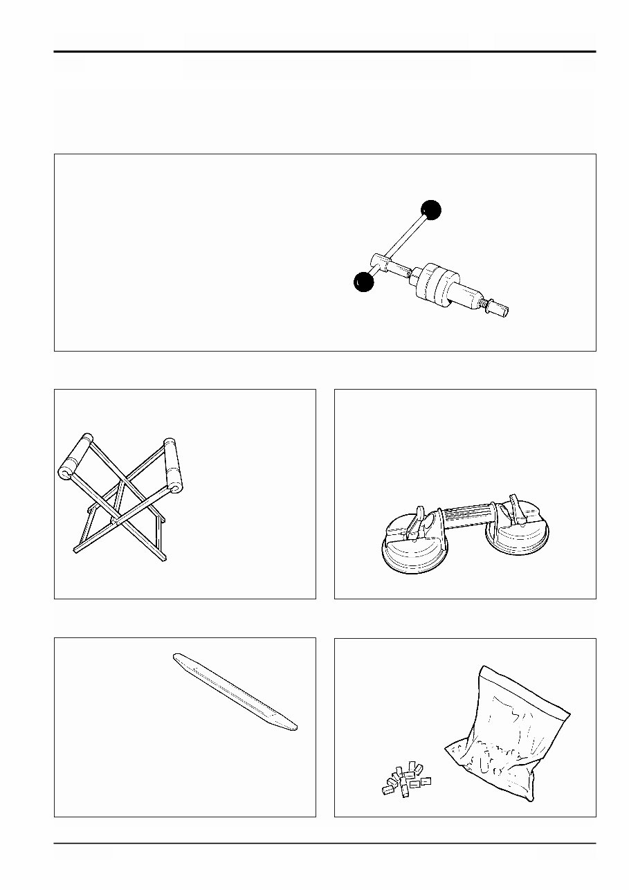
3 - 3 Section 1 General Information 9803/3610 Section 1 3 - 3 Issue 1* Service Tools Section B - Body and Framework 826/01176 M6 x 16mm Rivet Nut 826/01106 M6 x 19mm Rivet Nut 826/01177 M8 x 18mm Rivet Nut 826/01176 M10 x 23mm Rivet Nut 826/01333 M10 x 26mm Rivet Nut Installation Tool Available from: Bollhoff Fastenings Ltd. Midacre The Willenhall Estate Rose Hill Willenhall West Midlands, WV13 2JW S150970 Folding Stand for Holding Glass - essential for preparing new glass prior to installation. JCB part number - 892/00843 S186280 Glass Lifter - minimum 2 off - essential for glass installation, 2 required to handle large panes of glass. Ensure suction cups are protected from damage during storage. JCB part number - 892/00842 S186300 Nylon Spatula - general tool used for smoothing sealants - also used to re-install glass in rubber glazing because metal tools will chip the glass edge. JCB part number - 892/00847 S186470 Rubber Spacer Blocks - used to provide the correct set clearance between glass edge and cab frame. JCB part number - 926/15500 (unit quantity = 500 off) S186550
This is the COMPLETE official full factory service repair manual for the JCB 520-55 Loadall. Hundreds of pages allow you to print it out in its entirety or just the pages you need!! Its important to buy the right repair manual for your JCB 520-55 Loadall. This JCB 520-55 Loadall service manual provides data, characteristics, instructions and methodology to perform repair interventions on the vehicle and its components. This manual includes special notes, important points, service data, precautions, etc. that are needed for the maintenance, adjustments, service, removal and installation of vehicle components for JCB 520-55 Loadall. It is great to have, will save you a lot and know more about your JCB 520-55 Loadall, in the long run.
This JCB 520-55 Loadall service manual is your number one source for repair and service information. They are specifically written for the do-it-yourselfer as well as the experienced mechanic. Using this JCB 520-55 Loadall repair manual is an inexpensive way to keep you vehicle working properly. Information in this manual for JCB 520-55 Loadall is divided into groups. These groups contain general information, diagnosis, testing, adjustments, removal, installation, disassembly, and assembly procedures for the systems and components. Appropiate service methods and correct repair procedures are esential for the safe, reliabe operation of all motor vehicles as well as the personal safety of the individual carrying out the work. JCB 520-55 Loadall service manual provides step-by-step instructions based on the complete disassembly of the machine. It is this level of detail, along with hundreds of photos and illustrations, that guide the reader through each service and repair procedure.
JCB 520-55 Loadall Workshop Service Repair Manual Includes the following aspects:
JCB 520-55 Loadall General Information
JCB 520-55 Loadall Care and Safety
JCB 520-55 Loadall Routine Maintenance
JCB 520-55 Loadall Attachments
JCB 520-55 Loadall Body and Framework
JCB 520-55 Loadall Electrics
JCB 520-55 Loadall Hydraulics
JCB 520-55 Loadall Transmission
JCB 520-55 Loadall Brakes
JCB 520-55 Loadall Track and Running Gear
JCB 520-55 Loadall Engine
And MORE !!
Simply print out the pages you need or print the entire manual as a whole!!!
Detailed substeps expand on repair procedure information
Notes, cautions and warnings throughout each chapter pinpoint critical information.
Numbered instructions guide you through every repair procedure step by step.
Bold figure number help you quickly match illustrations with instructions.
Detailed illustrations, drawings and photos guide you through every procedure.
Enlarged inset helps you identify and examine parts in detail.
Numbered table of contents easy to use so that you can find the information you need fast.
This JCB 520-55 Loadall service manual also makes it easy to diagnose and repair problems with your machines electrical system. Troubleshooting and electrical service procedures are combined with detailed wiring diagrams for ease of use.
GET YOUR JCB 520-55 Loadall SERVICE MANUAL NOW!
This manual for JCB 520-55 Loadall has been issued to provide you with technical information regarding the design, function, disassembly, adjusting work and troubleshooting on the components and model of the JCB 520-55 Loadall. The descriptions are brief but precise and are supported by photographs, notes, drawings and schematics, as well as exploded and sectional drawings. All this information is intended to simplify any necessary repair work which can be performed on JCB 520-55 Loadall. Complete comes in format which can work under all PC based windows operating system and Mac also. It saves to your hard-drive and can be burned to CD-ROM. All pages are printable. No need to pay for shipping and wait for the overpriced paper textbook or CD-ROM to arrive via snail mail.
IT NOW!!
PRODUCT DETAILS:
File Format:
Language: English
Printable: without any restriction
Delivery: link will appear on the checkout page after payment is complete.