Section A - Attachments A - 0 A - 0 9803/3640U-5 Page left intentionally blank
Page No. Contents Section B - Body and Framework B - i B - i Service Procedures Rivet Nuts ............................................................................................... B - 1 Slide Hammer Kit .................................................................................... B - 3 Boom Removal and Replacement .................................................................... B - 4 Boom Shimming ..................................................................................... B - 6 Boom Chains Servicing ............................................................................................... B - 12 Removal, Inspection and Replacement ................................................ B - 15 Combined Fuel and Hydraulic Tank Removal and Replacement .................................................................. B - 19 Cab Removal and Replacement .................................................................. B - 23 Glazing ................................................................................................. B - 25
Page No. Contents Section B - Body and Framework B - ii B - ii
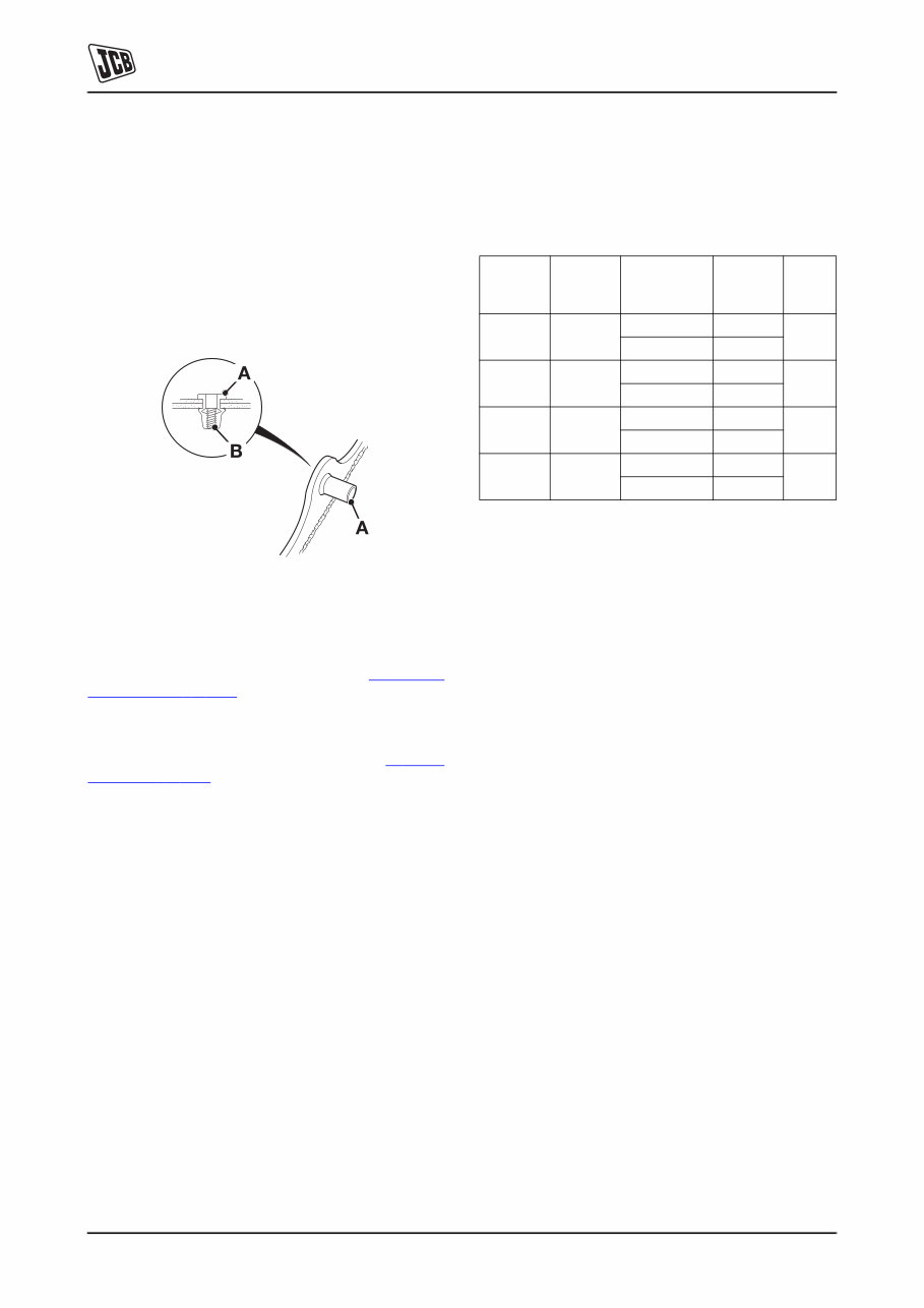
Section B - Body and Framework B - 1 B - 1 9803/3640U-5 Service Procedures Rivet Nuts TB-001_2 A 'Rivet Nut' is a one piece fastener installed 'blind' from one side of the machine body/framework. The rivet nut 1- A is compressed so that a section of its shank forms an 'upset' against the machine body/framework, leaving a durable thread 1-B. Fig 1. Rivet nuts are fitted to various parts of the machine body and framework. They are used in a number of applications, for instance, hose clamp and hydraulic valve retention etc. Various sized rivet nuts are available. K Table 1. Specifications ( T B-1) to determine the size of rivet nut to be used for particular applications. If for any reason a new rivet nut requires fitting, then the correct installation procedure must be followed. K Fitting Procedure ( T B-2) . Note: In an emergency, and if no installation tool is available, it is possible to fit a rivet nut by using a nut and bolt the same thread diameter as the rivet nut being installed. However, this is not the recommended method. Table 1. Specifications Note: All dimensions in mm Rivet Nut Thread Diameter Rivet Nut Outside Diameter Material Thickness Rivet Length (Total) Drill Hole Dia. M5 7 0.25 - 3.00 14.00 7.10 3.00 - 5.50 17.00 M6 9 0.50 - 3.00 16.00 9.10 3.00 - 5.50 19.00 M8 11 0.50 - 3.00 18.00 11.10 3.00 - 5.50 21.00 M10 13 1.00 - 3.50 23.00 13.10 3.50 - 6.00 26.00
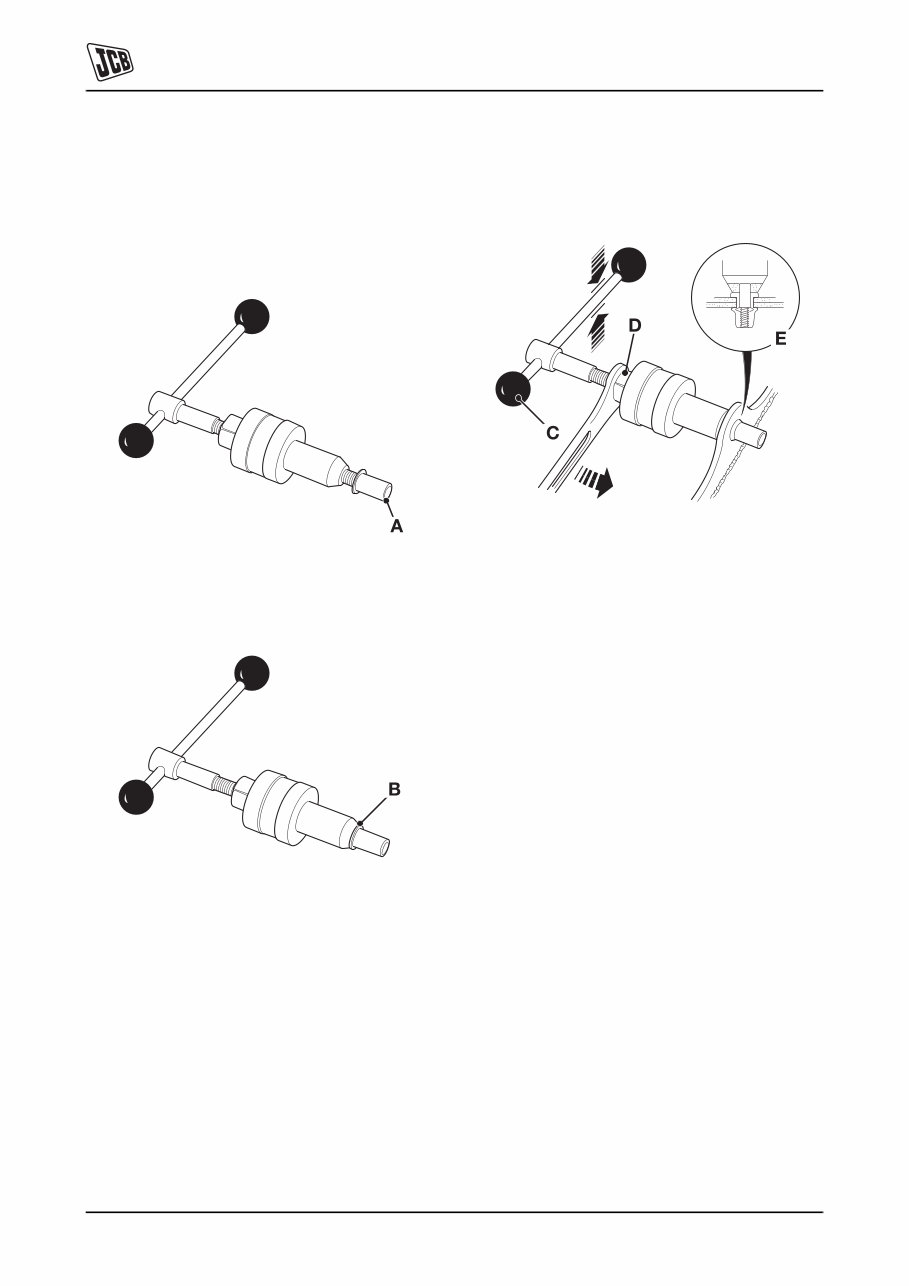
Section B - Body and Framework Service Procedures Rivet Nuts B - 2 B - 2 9803/3640U-5 Fitting Procedure 1 Drill a hole in the machine body/framework where the rivet nut is to be fitted. De-burr hole edges. 2 Screw the rivet nut onto the mandrel of the installation tool. The bottom of the mandrel should be in line with the bottom of the rivet nut 2-A. Fig 2. 3 Wind the body of the installation tool down the threaded mandrel until it touches the head of the rivet nut 3-B. Fig 3. 4 Insert the rivet nut (assembled to the tool) into the hole drilled in step 1. 5 Hold handle 4-C and at the same time draw the mandrel into the installation tool by turning nut 4-D. The rivet nut will contract in length and form an 'upset' (smooth bulge) seating itself against the body/ framework 4-E. Note: The thread of the rivet nut must not be stripped, take care when 'upsetting' the rivet nut. Fig 4. 6 Remove the installation tool.
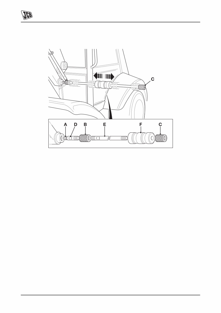
Section B - Body and Framework Service Procedures Slide Hammer Kit B - 3 B - 3 9803/3640U-5 Slide Hammer Kit TB-003 Fig 5. Typical M/c. Installation The slide hammer kit is used to remove pivot pins that must be extracted, i.e. cannot be 'knocked through'. The purpose of this description is to explain how the kit and the various components are used to remove the pivot pins. The adaptors 5-A that form part of the kit have a screwed thread at each end. One of the threads will always be M20 size, this is to accommodate the end stops, items 5-B and 5-C. The other end of the adaptor will have varying thread sizes to suit the different size of threads in the pivot pins. Fitting Procedure 1 Prepare the pivot pin, for instance, if fitted, remove the pivot pin retaining bolt. 2 Determine the thread size of the pivot pin and then fit the appropriate adaptor 5-A as shown. Use the spanner flats 5-D to securely fit the adaptor. 3 Fit an end stop 5-B onto the other end of the adaptor (M20 thread size), make sure that the adaptor threads are fully engaged. 4 Fit the 'slide bar' 5-E into the end stop. Again make sure that the threads are fully engaged. 5 Fit the 'slide hammer', item 5-F, onto the slide bar as shown. 6 Finally, fit another end stop, item 5-C, at the end of the slide bar, as shown. The slide hammer kit is now ready to use. 7 To extract the pivot pin, slide the hammer along the bar until it contacts end stop 5-C. Repeat this step until the pivot pin is released. 8 To remove the slide hammer kit, reverse steps 2 to 7.
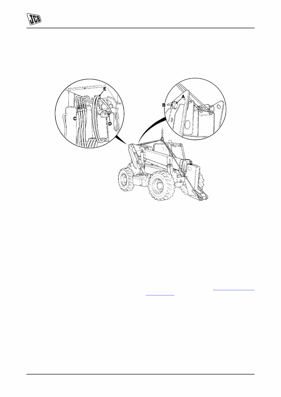
Section B - Body and Framework B - 4 B - 4 9803/3640U-5 Boom Removal and Replacement Fig 6. Removal 1 Position machine on level ground and apply parking brake. Stop engine. 2 Remove Q - Fit carriage. 3 Operate tilt ram control to vent residual pressure. 4 Remove boom rear cover and support boom with appropriate lifting equipment. 5 Disconnect hydraulic hoses from boom to base. Label hoses for identification. 6 Disconnect hydraulic hoses to hose burst protection valve. 7 Disconnect lift rams rod ends. 8 Disconnect displacement ram rod end. 9 Unscrew bolt 6A and withdraw pivot pin 6B. 10 Remove boom from machine with appropriate lifting equipment. 11 Remove hoses from boom. Replacement Replacement is reversal of removal procedure. Re-shim the boom as required. K Re-Shimming the Boom ( T B-5) . Grease pivot pins with specified grease. See Greasing, Section 3.
Section B - Body and Framework Boom Removal and Replacement B - 5 B - 5 9803/3640U-5 Re-Shimming the Boom Fig 7. Note: The illustration shows the boom viewed from the rear of the machine. 1 Measure 7X and 7Y. 2 Use the following illustration to calculate the total gap 7Z: Total Gap 7Z = 7X + 7Y 3 Add the correct quantity of shims. K Table 2. Boom Pivot Shimming Details ( T B-5) . Table 2. Boom Pivot Shimming Details Total Gap 7Z Shim Position and Quantity 7X 7Y 1 to 2 mm - - 2 to 3.75 mm 1 off - 3.75 to 5.25 mm 1 off 1 off 5.25 to 7 mm 2 off 1 off
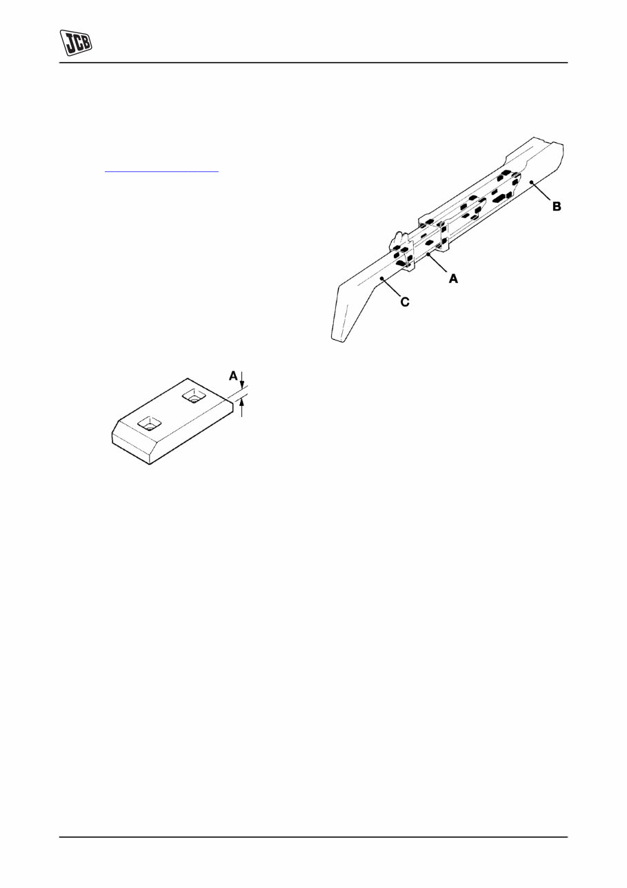
Section B - Body and Framework Boom Boom Shimming B - 6 B - 6 9803/3640U-5 Boom Shimming Typical Method This procedure details a typical method for shimming a boom. K Measurements ( T B-9) , for specific information. Shims are fitted under the pads for adjustment of boom clearance. Partly worn pads may be shimmed to restore correct boom clearance. Note: Do not fit spring washers. Notice: Later type wear pads are red in colour and can be used to replace the older type but must be used in pairs for equal wear. Do not replace the new type wear pad with the older type. Renew the wear pads when, or before they are worn down to depth of chamfer as shown at 8A. Fig 8. On 3 stage machines shim intermediate boom 9A to outer boom 9B then repeat the procedure for inner 9C to intermediate boom 9A. Fig 9. 3 Stage Boom
JCB LOADALL 508C SERVICE AND REPAIR MANUAL is a comprehensive factory manual designed to assist in the repair and maintenance of your vehicle. Whether you are a professional mechanic or a DIY enthusiast, this manual provides detailed instructions and procedures for addressing vehicle issues.
Our repair manual includes:
Engine illustrations
Technical description
Engine data tag, cylinder description, direction of rotation, and engine identification number
Additional information about this service repair manual:
Compatible with all versions of Windows and Mac
Language: English
Printable
Requirements: Adobe Reader and WinZip (free online)
All pages are printable, allowing you to easily access the information you need. Should you have any specific questions or needs, feel free to email us for assistance. This manual provides step-by-step instructions, diagrams, illustrations, wiring schematics, and specifications to facilitate vehicle repair with ease. Say goodbye to flipping through books or dealing with greasy and torn paper manuals. Our manuals are compatible with Windows Vista32 and 64, XP, ME, 98, NT, 2000, and Mac. We accept all major credit/debit cards and PayPal.