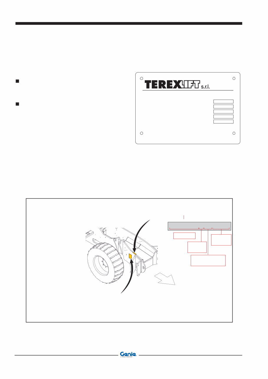
Machine Identification May 2008 CHASSIS SERIAL NUMBER The chassis serial number is punched on the front left part of the chassis side member. IDENTIFICATION PLATES OF THE MAIN PARTS The plates of the main components, not directly manufactured by TEREXLIFT srl (for instance, engines, pumps, etc.), are located where originally applied by the manufacturers. HOW TO READ YOUR SERIAL NUMBER Chassis serial number (The chassis serial number is punched on the front left part of the chassis side member) GTH-4013 P 07 17882 MODEL ENGINE TYPE YEAR OF MANUFACTURER SERIAL NUMBER Lb ona Industriale 00 Umbertide (PG) Italy TRUC CAPACITY UNLADEN TRUC MA IMUN EIG T SERIAL NUMBER MADE IN ITALY MODEL NUMBER YEAR OF MANUFACTURE Lb T IS TRUC IS COMPLIANT TO PART III OF ASME B . 2002 ERE APPLICABLE MACHINE DATA PLATE Machine Identification Machine data plate IDENTIFICAZIONE MACCHINA Document 57.4403.4200 GTH-4013 SX GTH-4017 SX iv
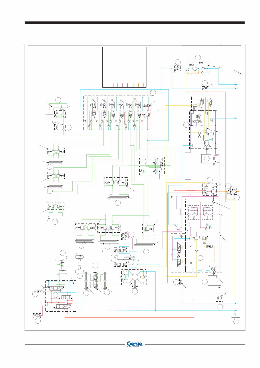
May 2008 Description DESCRIPTION OF THE MACHINE OPERATION The mechanical energy source of these machines is a (1) Perkins diesel engine model 1104/d-44T, which supplies a 74,5 kW at 2300 rev/min with a max torque of 392 Nm at 1400 rev/min. On the flywheel side of the engine, and connected to the same by a Technodrive coupler complete with elastic joint and with a 1-to-1 ratio, there is Sauer danfoss closedloop pump for hydrostatic drives, model H1P078 (2). max displacement of this swashplate pump is 78 cm 3 /rev, and the max calibration pressure is 450 bar. This pump is used to supply hydraulic power under form of pressure and flow rate which is then used for moving the machine. On the through-shaft of such drive pump there is a Casappa open-loop gear pump (with fixed displacement) (3) with priority valve integrated in the housing. The displacement of this pump is 43 cm 3 /rev. Its function is to provide hydraulic power, under form of pressure and flow rate, to the steering circuit of the machine (primary branch of the priority valve) and to the circuit for the telescopic boom movements (secondary branch of the priority valve). The assembly of the two pumps involves they have a rotation velocity equal to the speed of the diesel engine. A third Casappa open-loop gear pump (with fixed displacement) (4) with a displacement of 20 cm 3 /rev., is installed on the PTO of the engine located to the distribution side. This pump feeds the servo-assisted braking system (25). The suction lines of the open-loop pumps (3) and (4) are protected by an immersed filter (8), placed inside the hydraulic fluid tank (10) whose capacity is 130 litres. Just upstream of the connection with the three suction lines mentioned above, there is a gate valve with ball valve (9) which lets you cut out the hydraulic oil tank in order to perform maintenance interventions on the machine's hydraulic system. The drive pump (2) is protected by a special filter (34), placed on the pump drain line (3). This filter purifies the oil coming from the main openloop circuit of the machine (telescopic boom operating circuit) and, when needed, supplies oil at a minimum pressure of 0.5 bar to the transmission suction line. This construction feature of the filter guarantees important advantages in terms of absence of cavitation in the transmission suction line, especially when the machine is started from cold. The one-way valve (11) set at 2.5 bar protects the pump housing against high pressures and guarantees a certain circulation of the drain oil to the hydrostatic motor reducing, in this way, the temperature. From port “M3” of the drive pump (2) low-pressure oil is taken (25-30 bar) and used for the anti-cavitation circuit of the automatic fork levelling system. The hydraulic energy produced by the drive pump (2) is converted into mechanical power by a closed-loop hydrostatic motor, model Sauer danfoos 51D110 (5). The max displacement of this bent-axis motor is 80 cm 3 /rev. The motor is directly flanged to the Dana single-speed reduction gear (26), which is fixed with brackets to the central zone of the chassis. The mechanical torque at the gearbox output is transmitted to the front axle (6) and the rear axle (27), both model 212 manufactured by Dana, through Cardan shafts. The hydraulic drive (12) of “load sensing” type with a displacement of 315 cm 3 / rev., receives oil from the priority line of the pump (3) in relation to the “load sensing” signal sent by the hydraulic drive and connected to such pump with function of pilot signal. In this way, the input flow to the hydraulic drive is exactly the one needed for the instantaneous steering functions; any excess flow of the pump is available for the functions of the telescopic boom. The steering circuit is protected against input overpressures by a pressure reducing valve set at 140 bar. On the two delivery lines to the steering cylinders there are other two pressure reducing valves with anti-shock function set at 200 bar. These two valves are intended to limit possible shocks on the steering wheel due to overstress on the steering cylinders. The three pressure reducing valves are installed in the hydraulic drive (12) and cannot be regulated from the outside. The steering circuit is completed by the front steering cylinder (14), the rear steering cylinder (15) (these cylinders being integral part of the front axle (6) and the rear axle (27) respectively) and by a 4-way/3-position solenoid valve (13) for the selection of the three different steer modes (rear wheels straight, co-ordinate front/rear steering and independent front/rear steering). When the solenoid valve (13) is not energised, the front steering cylinder is fed by the hydraulic drive and the rear cylinder is blocked. When one magnet or the other of the solenoid valve (13) is energised, the chambers of the cylinders are connected in a different manner thus causing the desired effect on the steering mode. The Walvoil 6-section valve block of mechanical type (16) receives oil from the secondary line of the pump (3) and feeds all the movements of the telescopic boom, as well as the outriggers and the chassis sway function. This monoblock valve is the 6-way type, with oil which flows through the main valve Description Document 57.4403.4200 v GTH-4013 SX GTH-4017 SX
Description May 2008 when the controls are not activated, and then to the tank. When the mechanical lever controls are activated, the movement of the main valve sliders chokes the oil flow, thus producing the necessary pressure for the control of the activated function. Each of the 6 sections of the main valve control a specific function of the machine (lifting/lowering, attachment holding plate rotation, boom extension/ retraction, attachment locking/unlocking, outriggers and chassis sway function). In the head there is a pressure relief valve set at 270 bar also serving as a safety valve of the circuit which directly acts on the main line of the hydraulic oil. Again in the input head of the main valve there is a solenoid valve discharging the main flow which activates the movements of the main valve only when its solenoid is energised. When such solenoid is not energised all the flow from the pump is discharged. In this specific version of the machine, this solenoid valve is mainly used to stop some movements of the machine when the stability limits are reached, and also to completely deactivate such functions when the relevant selector in the driving place is turned to the "road" position. By moving the main lever in the driving place to one side, section 1 of the main valve directly delivers oil to the oil-dynamic block (37) consisting of a 6-way/2 position electrical switch block and 3 pressure relief valves. Two of these valves, calibrated at 295 bar, are mounted on the lines controlling the rotation of the attachment holding frame; the third one, set at 200 bar, is installed on the extension line of the telescopic boom lifting cylinder. When the coil of the electrical switch block is not energised, the oil coming from section 1 of the main valve is sent to the extension cylinders (21) and (22 only for GTH-4013 SX) of the telescopic boom, connected in series with each other. Cylinder (21), which activates the second telescope of the boom, is equipped with a double-acting compensation valve serving also as a safety valve, while cylinder (22), which activates the third telescope of the boom, is equipped with a singleacting compensation valve again serving also as a safety valve. This pressure relief valve set at 200 bar and fitted to the oil-dynamic block (37), reduces the maximum load during the boom extension phase in those work areas where the electronic moment limiting system cannot detect overload conditions with respect to the admissible load chart of the machine. When the coil of the electrical switch block is energised by the activation of the pushbutton placed at the top of the main lever in the cab, oil is sent to the attachment holding frame cylinder (19) of the telescopic boom. This cylinder is equipped with a double-acting compensation valve serving also as a safety valve. Parallel to this cylinder, there is the fork levelling compensation cylinder (20) (also called balancing cylinder) which is equipped with a special double-acting compensation valve. Inside this valve, the one-way valves are mounted in reversed manner with respect to the normal position to avoid the pressurisation of the cylinder when the rotation control of the attachment holding frame is activated. Again inside this valve, there are other two one-way valves (36), set at 5 bar, serving as anti-cavitation check valves. These valves deliver oil, taken from the low-pressure line of the transmission pump (2), to the fork levelling compensation circuit when needed. The two pressure relief valves set at 295 bar and mounted in the oil-dynamic block (37), protect the automatic fork levelling circuit during the boom lifting/lowering phases and in all cases of overload on the attachment holding frame (for instance, in the case of use of the bucket). Section 2 of the main valve (16) controls the telescopic boom lifting cylinder (17) through the longitudinal displacement of the main lever placed in the driving cab. This cylinder has one single-acting compensation valve with safety function. Section 3 of the main valve controls the chassis sway cylinder (31) mounted on the right side of the machine and equipped with a double-acting compensation valve serving also as a safety valve, through the lateral displacement of the special lever installed in the driving place. Section 4 of the main valve controls the left outrigger cylinder (29) equipped with double-acting compensation valve serving also as a safety valve, through the longitudinal displacement of the special lever placed in the driving cab. Section 5 of the main valve controls the right outrigger cylinder (30) equipped with double-acting compensation valve serving also as a safety valve, through the longitudinal displacement of the special lever placed in the driving cab. Section 6 of the control valve controls the attachment locking cylinder (23) through the lateral displacement of the special lever placed in the driving place. This cylinder has a double one-way valve with hydraulic release and safety function. On the feeding lines of this cylinder, there are two quickfit connectors (24) for the connection of the hydraulic lines to those optional attachments necessitating hydraulic power for their operation (ex. hydraulic winch and maintenance jib, mixing bucket, etc.). In the model dealt with in this manual, this function is optional. All the sections of the main valve (16) are equipped with a micro-switch which senses and transmits a special ON/ OFF signal when the relevant slider is activated. Such signals are used by the operating logic of the system protecting the machine in case of loss of stability (LMI). The SAFIM S6 servo-assisted braking system with pedal (25) receives oil from pump (4) and uses this oil to pressurise a hydraulic accumulator (39) connected to DESCRIZIONE Document 57.4403.4200 GTH-4013 SX GTH-4017 SX vi
May 2008 Description the same system. The oil at pressure contained in this accumulator is then used to operate the service brake placed inside the rear axle (27). The braking effect produced by the braking axle is then transferred to the front axle through Cardan shafts connecting the axles to reduction gear (26). The fill valve inside the braking system takes the flow from the feeding line so the pressure on the accumulator line reaches the calibration value of the cutout valve set at 150 bar. When this pressure is reached, the valve gradually releases all the flow to line B for other uses. The brake pedal located in the driving cab, which is an integral part of the braking system S6, is connected to a slider of proportional type which controls the line of the service brake. In relation to the stroke of this slider, a gradual communication between the feeding line, connected to an accumulator (39) with 0.5 lt. capacity and a fill pressure of 50 bar, connected, at its turn, to port R1, and the service brake line is established so the flow is distributed to such line and the discharge line increasing, in this way, the pressure (and as a result the braking force) on the line of the service brake. When the slider is in the rest position, the line of the service brake is connected to the discharge. The pressure switch set at 70 bar (38) and connected to port F, sends an electrical warning signal when the pressure inside the feeding circuit of the brake line is too low to guarantee the minimum braking efficiency. The oil coming from the drain line of the main valve (16) is cooled down by heat exchanger (32) which is divided in two sectors, i.e. one absorbing heat from the cooling circuit of the diesel engine and the other absorbing heat from the hydraulic circuit of the machine. The oil cooled down by the heat exchanger is sent back to the special filter (34) which is also used to deliver fluid at pressure to the transmission booster pump, and finally drained into tank (10). A one-way valve calibrated at 8 bar (33), is installed parallel to the input line of the heat exchanger and used as safety valve. Its function is to avoid overpressure conditions of the heat exchanger (as is the case of a machine starting at low temperatures) by directly draining any excess oil into the tank. The oscillation of the rear axle of the machine is controlled by a block cylinder (35) whose two chambers are equipped with sealed 2-way/2-position solenoid valves. When the two solenoid valves are de-energised, the circular and annular chambers of the cylinder are closed toward the outside and the cylinder behaves like a strut/ tie-rod blocking in this way the rear axle. This happens when the inclination of the telescopic boom exceeds a certain pre-set value of 50° and the side stability of the machine must be improved. When, on the contrary, the boom inclination is below such pre-set value, the two solenoids of the solenoid valves are energised thus letting the oil circulating freely from/to the two chambers of the cylinder. In this way, the axle can oscillate, thus making the machine drive more comfortable even in case of rough terrains. The chambers of the cylinder are always kept filled with oil by a single hydraulic line connected to the housing of the drive pump (2). This allows to have a minimum pressure capable of keeping the circuit of the rear axle block cylinder full of oil but incapable of producing overloads on the same axle. DESCRIZIONE Document 57.4403.4200 vii GTH-4013 SX GTH-4017 SX
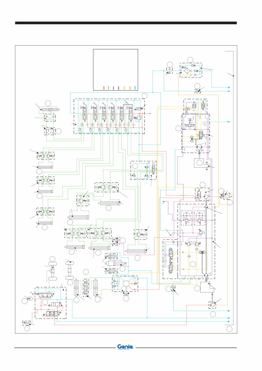
Description May 2008 GTH 4013 SX hydraulic schematic DESCRIZIONE N R F P B N’ L S L R T P Anticavitation valve cracking pressure 5 bar Steering rotating actuator displacement: 315 cc rev / Rear axle Forks levelling slave cylinder Left stabilizer cylinder Right stabilizer cylinder Chassis levelling cylinders Second section boom telescoping cylinder Third section boom telescoping cylinder Boom lift cylinder Forks tilt cylinder Double overcenter safety valve piloting ratio: 4 1 cracking pressure: 350 bar / Double overcenter safety valve piloting ratio: 4.2 1 cracking pressure: 350 bar / Double overcenter safety valve piloting ratio: 4.2 1 cracking pressure: 350 bar / Double overcenter safety valve piloting ratio: 4.2 1 cracking pressure: 350 bar / Double overcenter safety valve piloting ratio: 7.6 1 cracking pressure: 350 bar / Double overcenter safety valve piloting ratio: 4/1 cracking pressure: 350 bar Sing 4/ le overcenter safety valve piloting ratio: 1 cracking pressure: 350 bar Sing 4/ le overcenter safety valve piloting ratio: 1 cracking pressure: 350 bar Max relief valve cracking pressure 140 bar Anti-shock valves cracking pressure 200 bar Quick coupling hydraulic ports Quick coupling hydraulic cylinder Steering modes selector valve 4 ways / 3 positions Front axle steering cylinder Rear axle steering cylinder Hydraulically piloted double check valve piloting ratio: 4 1 / R1 T1 T1’ T A P B capacity: 0.5 Litri precharge pressure 50 bar Pressure switch activating pressure 70 bar Hydraulically powered service/emergency brakes pedal pump 150 bar Forks attachment quick coupling cylinder Boom functions main valve X31 X18 X19 X30 X17 Rear axle pivoting lockout cylinder Rear axle pivoting lockout valve 2 ways/2 positions A1 B1 B3 A3 B2 A2 A4 A5 A6 B4 B5 B6 T T P 270 bar Functions enabling valve TP 1 T A1 A2 B B1 B2 A Telescoping/forks tilt selector valve 6 ways/2 positions 295 bar 295 bar 200 bar HYDRAULIC CIRCUI T COLORS LEGENDA Hydraulic lines to/from actuators Low pressure lines Hydraulic piloting and load sensing lines High pressure lines (open circuits) High pressure lines (closed circuits) Hydraulic suction lines Tank lines M Diesel engine Auxiliary gear pum p displacement: 20 cc/rev Suction screen Check valve cracking pressure: 2.5 bar Oil tank capacity 130 liters Hydrostatic transmission motor max displacement: 107 cc rev / Gear box Return filter with suction line pressurized at 0,5 bar Check valve cracking pressure: 8 bar Shutoff valve F00B F00A MA M3 L1 L3 L4 L2 A B S M4 M14 M5 MB Boom functions pum p with integrated priority valve displacement: 43 cc/rev Hydrostatic transmission pump max displacement: 78 cc rev / Hydrostatic transmission pump displacement: cc rev charge 17 / XA XB A M3 M4 M1 L1 L2 M2 X5 X14 X7 X8 X3 B 24 bar 450 bar 450 bar 480 bar 480 bar Heat exchanger Return filter with suction line pressurized at 0,5 bar Tp2 Hydrostatic transmission high pressure test port Tp3 Hydrostatic transmission charge pressure test port Boom functions hydraulic circuit test port Forward Reverse Y1 X8 S B30 A B31 A B32 B35 A B34 B33 25 37 17 36 35 12 14 13 15 20 19 27 38 39 31 22 21 30 29 24 6 Front axle 1 4 11 2 3 26 8 9 10 5 34 33 32 16 23 Document 57.4403.4200 GTH-4013 SX GTH-4017 SX viii
May 2008 Description GTH 4017 SX hydraulic schematic DESCRIZIONE N R F P B N’ L S L R T P Anticavitation valve cracking pressure 5 bar Steering rotating actuator displacement: 315 cc rev / Rear axle Forks levelling slave cylinder Left stabilizer cylinder Right stabilizer cylinder Chassis levelling cylinders Boom telescoping cylinder Boom lift cylinder Forks tilt cylinder Double overcenter safety valve piloting ratio: 4 1 cracking pressure: 350 bar / Double overcenter safety valve piloting ratio: 4.2 1 cracking pressure: 350 bar / Double overcenter safety valve piloting ratio: 4.2 1 cracking pressure: 350 bar / Double overcenter safety valve piloting ratio: 4.2 1 cracking pressure: 350 bar / Double overcenter safety valve piloting ratio: 7.6 1 cracking pressure: 350 bar / Double overcenter safety valve piloting ratio: 4/1 cracking pressure: 350 bar Sing 4/ le overcenter safety valve piloting ratio: 1 cracking pressure: 350 bar Max relief valve cracking pressure 140 bar Anti-shock valves cracking pressure 200 bar Quick coupling hydraulic ports Quick coupling hydraulic cylinder Steering modes selector valve 4 ways / 3 positions Front axle steering cylinder Rear axle steering cylinder Hydraulically piloted double check valve piloting ratio: 4 1 / R1 T1 T1’ T A P B capacity: 0.5 Litri precharge pressure 50 bar Pressure switch activating pressure 70 bar Hydraulically powered service/emergency brakes pedal pump 150 bar Forks attachment quick coupling cylinder Boom functions main valve X31 X18 X19 X30 X17 Rear axle pivoting lockout cylinder Rear axle pivoting lockout valve 2 ways/2 positions A1 B1 B3 A3 B2 A2 A4 A5 A6 B4 B5 B6 T T P 270 bar Functions enabling valve TP 1 T A1 A2 B B1 B2 A Telescoping/forks tilt selector valve 6 ways/2 positions 295 bar 295 bar 200 bar HYDRAULIC CIRCUI T COLORS LEGENDA Hydraulic lines to/from actuators Low pressure lines Hydraulic piloting and load sensing lines High pressure lines (open circuits) High pressure lines (closed circuits) Hydraulic suction lines Tank lines M Diesel engine Auxiliary gear pum p displacement: 20 cc/rev Suction screen Check valve cracking pressure: 2.5 bar Oil tank capacity 130 liters Hydrostatic transmission motor max displacement: 107 cc rev / Gear box Return filter with suction line pressurized at 0,5 bar Check valve cracking pressure: 8 bar Shutoff valve F00B F00A MA M3 L1 L3 L4 L2 A B S M4 M14 M5 MB Boom functions pum p with integrated priority valve displacement: 43 cc/rev Hydrostatic transmission pump max displacement: 78 cc rev / Hydrostatic transmission pump displacement: cc rev charge 17 / XA XB A M3 M4 M1 L1 L2 M2 X5 X14 X7 X8 X3 B 24 bar 450 bar 450 bar 480 bar 480 bar Heat exchanger Return filter with suction line pressurized at 0,5 bar Tp2 Hydrostatic transmission high pressure test port Tp3 Hydrostatic transmission charge pressure test port Boom functions hydraulic circuit test port Forward Reverse Y1 X8.S B30 A B31 A B32 B35 A B34 B33 Front axle 6 25 14 13 15 20 19 27 38 39 31 21 29 11 17 36 35 12 1 4 2 3 8 9 10 26 34 33 32 5 37 16 30 23 24 Document 57.4403.4200 ix GTH-4013 SX GTH-4017 SX
Description May 2008 Intentionally blank page Document 57.4403.4200 GTH-4013 SX GTH-4017 SX x
You're Reading a Preview
What's Included?
Lifetime Access
Fast Download Speeds
Online & Offline Access
Access PDF Contents & Bookmarks
Full Search Facility
Print one or all pages of your manual
$32.99
Genie GTH-4013 SX, GTH-4017 SX Service Repair Workshop Manual INSTANT
Get the Genie GTH-4013 SX, GTH-4017 SX Service Repair Manual for instant access to professional technical service and repair guidance. This manual is designed for both do-it-yourselfers and experienced mechanics, featuring easy-to-read text sections, top quality diagrams, and step-by-step instructions for all repair areas. The manual is available in PDF format, compatible with all Windows and Mac operating systems. It includes safety rules, technical specifications, maintenance inspections and procedures, problem-solving, schemes, and repair procedures. With instant access upon payment completion, you can start your repairs immediately without waiting for postal delivery. Save on postage and packaging and get your vehicle working properly with this comprehensive manual.
Reviews
Q&A
Recently Viewed
5,521,897Happy Clients
2,594,462eManuals
1,120,453Trusted Sellers
15Years in Business
Price:
Actual Price:
Genie GTH-4013 SX, GTH-4017 SX Service Repair Workshop Manual INSTANT







 Lifetime Access




