


English
Service Manual
GTH-2506
AGRI-625
Serial number range
From serial n.: 18957
From serial n.: 19057
GTH-3007
AGRI-730
From serial n.: 19051
From serial n.: 19241
Part No. 57.0009.0419
April 2008
Service Manual April 2008
ii GTH 2506-3007 AGRI 625-730 Document 57.0009.0419
Intentionally blank page

Document 57.0009.0419 GTH 2506-3007 AGRI 625-730 iii
April 2008 Introduction
Introduction
Important information
Read, understand and obey the safety rules and operating
instructions in the GTH 2506 and AGRI 625 Operator's
Manual (code 57.0009.0413) and GTH 3007 e AGRI
730 Operator's Manual (code 57.0009.0445) before
attempting any maintenance or repair procedure.
This manual provides the machine owner and user with
detailed information on the scheduled maintenance. It also
provided qualified service technicians with infromation on
troubleshooting and repair procedures.
Basic mechanical, hydraulic and electrical skills are
required to perform most procedures. However, several
procedures require specialized skills, as well as specific
tools and equipment.
In these instances, we strongly recommend letting service
and repair the machine at an authorized TEREXLIFT
service center.
Technical Publications
No part of this publication may be reproduced, stored in a
retrieval system or transmitted in any form or by any means
without prior written permission from TEREXLIFT srl.
In pursuing a policy of constant quality improvement,
TEREXLIFT srl reserves the right to make changes at any
time and without undertaking to give prior notice; therefore,
also this publication may be subject to modifications.
Contact us
http://www.terexlift.com
e-mail: info@terexlift.it
http://www.genielift.com
© Copyright 2008 TEREXLIFT srl - All rights reserved
First Edition, First Printing, April 2008
For going to Table of Contents,
click on Genie symbol
iv GTH 2506-3007 AGRI 625-730 Document 57.0009.0419
Machine Identification April 2008
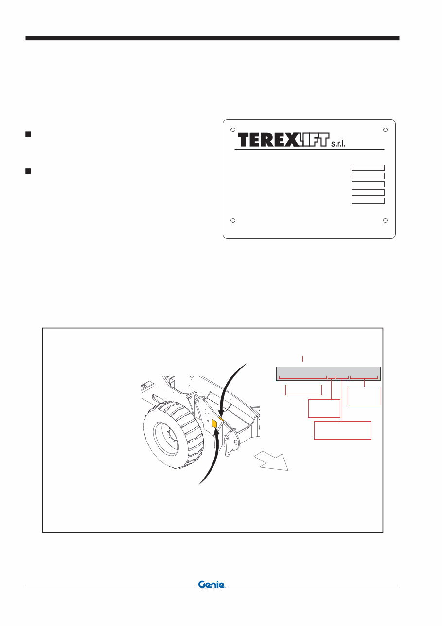
MACHINE IDENTIFICATION
CHASSIS SERIAL NUMBER
The chassis serial number is punched on the front left part of
the chassis side member.
IDENTIFICATION PLATES OF THE MAIN PARTS
The plates of the main components, not directly
manufactured by TEREXLIFT srl (for instance, engines,
pumps, etc.), are located where originally applied by the
manufacturers.
HOW TO READ
YOUR SERIAL
NUMBER
Chassis serial number
(The chassis serial number is punched on the front left
part of the chassis side member)
GTH-3007 P 07 17882
MODEL
ENGINE
TYPE
YEAR OF
MANUFACTURER
SERIAL
NUMBER
Lb
ona Industriale - 060 - Umbertide (PG) - Italy
TRUC CAPACITY
UNLADEN TRUC MAXIMUN EIGHT
SERIAL NUMBER
MADE IN ITALY
MODEL NUMBER
YEAR OF MANUFACTURE
Lb
THIS TRUC IS COMPLIANT TO PART III OF ASME B56.6 - 2002 HERE APPLICABLE
MACHINE DATA PLATE
Machine Identification
Machine data plate

Document 57.0009.0419 GTH 2506-3007 AGRI 625-730 v
April 2008 Description
DESCRIPTION OF THE MACHINE OPERATION
(GTH 2506 - AGR 625)
The mechanical energy source of this machine is a (1)
Deutz diesel engine model D2011 L04 Tier 3 which
supplies a 50 kW at 2600 rev/min (68 Hp) with a max
torque of 210 Nm (155 lb-ft) at 1700 rev/min.
On the flywheel side of the engine, and connected to the
same by a Technodrive coupler complete with elastic joint
and with a 1-to-1 ratio, there is Bosch-Rexroth closedloop
pump for hydrostatic drives, model A4VG56 (2) with
adjustment valve of DA type. The max displacement
of this swashplate pump is 56 cm3/rev. and the max
calibration pressure is 430 bar (6235 psi). This pump is
used to supply hydraulic power under form of pressure and
flow rate which is then used for moving the machine. On
the through-shaft of such drive pump there is a Casappa
open-loop gear pump (with fixed displacement) (3) with
priority valve integrated in the housing. The displacement
of this pump is 27 cm
3
/rev. Its function is to provide
hydraulic power, under form of pressure and flow rate, to
the steering circuit of the machine (primary branch of the
priority valve) and to the circuit for the telescopic boom
movements (secondary branch of the priority valve).The
assembly of the two pumps involves they have a rotation
velocity equal to the speed of the diesel engine. The
suction line of the open-loop pump (3) is protected by an
immersed filter (8), placed inside the hydraulic fluid tank
(10) whose capacity is 65 litres (17 gallons).
Just upstream of the connection with the suction line,
there is a gate valve with ball valve (9) which lets you cut
out the hydraulic oil tank in order to perform maintenance
interventions on the machine's hydraulic system without
having to drain oil off the tank built in the same circuit.
The filter (34), placed in the line returning to pump (3),
purifies most oil coming from the hydraulic circuit operating
the telescopic boom before this oil returns to the tank. In
addition to purify the oil coming from the main open-loop
circuit of the machine (telescopic boom operating circuit),
this filter can deliver oil at a minimum pressure of 0.5 bar
to the suction line of the drive pump (2). This construction
feature of the filter guarantees important advantages in
terms of absence of cavitation in the transmission suction
line, especially when the machine is started from cold.
The one-way valve (11) set at 2.5 bar (36 psi) protects the
pump housing against high pressures and guarantees a
certain circulation of the drain oil to the hydrostatic motor
reducing, in this way, the temperature. From port “G” of
the drive pump (2) low-pressure oil is taken (25-30 bar) to
feed the anti-cavitation circuit of the automatic fork levelling
system, the pilot circuit of the main valve of the telescopic
boom (16) and the parking brake unlock circuit.
The hydraulic energy produced by the drive pump (2)
is converted into mechanical power by a closed-loop
hydrostatic motor, model Bosch-Rexroth A6VM107 (5)
equipped with adjustment valve of DA1 type and with
flush valve (36) for reducing the max temperatures inside
the drive circuit. The max displacement of this bent-axis
motor is 107 cm
3
/rev. The motor is directly flanged to the
front steering axle (26).
The mechanical torque produced by the drive motor is
transmitted to the rear axle (27) through a Cardan shaft.
The hydraulic drive (12) of “load sensing” type with a
displacement of 125 cm
3
/rev., receives oil from the priority
line of pump (3) in relation to the “load sensing” signal
sent by the hydraulic drive and connected to such pump
with function of pilot signal. In this way, the input flow
to the hydraulic drive is exactly the one needed for the
instantaneous steering functions; any excess flow of the
pump is available for operating the different movements
of the telescopic boom. The steering circuit is protected
against input overpressures by a pressure reducing valve
set at 170 bar (2465 psi). On the two delivery lines to the
steering cylinders there are other two pressure reducing
valves with anti-shock function set at 225 bar (3262 psi).
These two valves are intended to limit possible shocks
on the steering wheel due to overstress caused by the
wheels on the steering cylinders. These pressure reducing
valves are installed in the hydrostatic drive (12) and
cannot be regulated from the outside. The steering circuit
is completed by the front steering cylinder (14), the rear
steering cylinder (15) (these cylinders being integral part
of the front axle (26) and the rear axle (27) respectively)
and by a 4-way/3-position solenoid valve (13) for the
selection of the three different steer modes (rear wheels
straight, co-ordinate front/rear steering and independent
front/rear steering). When the solenoid valve (13) is not
energised, the front steering cylinder is fed by the hydraulic
drive and the rear cylinder is blocked. When one magnet
or the other of the solenoid valve (13) is energised, the
chambers of the cylinders are connected in a different
manner thus causing the desired effect on the steering
mode. The Walvoil hydraulic 4-section main valve (16)
receives oil from the secondary line of pump (3) and feeds
all the movements of the telescopic boom. Each of the
4 sections of the main valve controls a specific function
of the machine (lifting/lowering, attachment holding plate
rotation, boom extension/retraction, attachment locking/
unlocking). In the head there is a pressure relief valve set
at 280 bar (4061 psi) which reduces the max pressure at
the main valve inlet and drains the excess oil.
Slider 1 of the main valve controls the lifting cylinder (17)
of the telescopic boom. This cylinder has one single-acting
compensation valve with safety function (18). Slider 2 of
Description

vi GTH 2506-3007 AGRI 625-730 Document 57.0009.0419
Description April 2008
DESCRIPTION
the main valve controls the attachment holding frame
cylinder (19) of the telescopic boom. This cylinder is
equipped with a double-acting compensation valve (21)
serving also as a safety valve.
Parallel to this cylinder, there is the fork levelling
compensation cylinder (20) (also called balancing
cylinder) which is equipped with a special double-acting
compensation valve (30). Inside this valve, the one-way
valves are mounted in reversed manner with respect to the
normal position to avoid the pressurisation of the cylinder
when the rotation control of the attachment holding frame
is activated. Again inside this valve, there are other two
one-way valves, set at 5 bar (72 psi), serving as anti-
cavitation check valves (6). These valves deliver oil, taken
from the low-pressure line of the transmission pump (2),
to the fork levelling compensation circuit when needed.
The two pressure relief valves (7) set at 300 bar (4351
psi) which protect the automatic fork levelling circuit during
the boom lifting/lowering phases and in case of overload
on the attachment holding frame (for instance, in the case
of use of the bucket) are installed in the two control lines
of cylinder (19) and they are integral to module 2. Slider
3 of the main valve controls the extension cylinder (22)
of the telescopic boom which operates the movement of
the second boom telescope and is equipped with a single-
acting compensation valve (31) used as well as safety
valve. Slider 4 of the main valve controls the attachment
locking cylinder (23). This cylinder has a double one-way
valve (35) with hydraulic release and safety function. On
the feeding lines of this cylinder, there are two quick-fit
connectors (24) for the connection of the hydraulic lines to
those optional attachments necessitating hydraulic power
for their operation (ex. hydraulic winch and maintenance
jib, mixing bucket, etc.).
The head has been designed to group, in a single element,
some valves of the lowpressure circuit fed through port
“G” of pump (2). In particular, the selection solenoid
valve (29) operates the parking brake and the relevant
valve controlling the flow rate of the calibrated throttle
with 0.5mm diameter.
The pressure reducing valve with screw adjustment (38),
set at 32 bar (464 psi), allows a maximum pressure to
move the sliders, the negative emergency brake and the
feeding line of the balancing cylinder.
The safety pressure switch (28), set at 20 bar (290 psi),
is collocated on one of the hydraulic ports of the feeding
line of the parking brake. This pressure switch prevents
the machine from moving when the pressure of the
parking brake line is too low to guarantee the complete
release of this brake.
The circuit of the service brake is operated by a SAFIM
27-20 pump (25) which takes hydraulic oil from tank (37)
to operate the service brake, located inside the front axle
(26). The brake pump can provide a maximum pressure of
80 bar (1160 psi), thus depending on the pressure exerted
on the brake pedal placed inside the driving place. The
pressure switch (4) set at 2.8-6.3 bar (40 - 90 psi), placed
on the pump head, sends an electrical signal when the
service brake is engaged. The oil coming from the drain
line of the main valve operating the telescopic boom (16)
is cooled down by the heat exchanger (32).
This exchanger is divided in two sectors, the former
absorbs heat from the cooling circuit of the diesel engine
and the latter absorbs heat from the hydraulic circuit of
the machine. The oil cooled down by the heat exchanger
is sent back to the special filter (34) and finally drained
into tank (10). A one-way valve (33) calibrated at 8 bar
(116 psi), is installed parallel to the input line of the heat
exchanger and used as safety valve. Its function is to
avoid overpressure conditions of the heat exchanger (as
is the case of a machine starting at low temperatures) by
directly draining any excess oil into the tank.

Document 57.0009.0419 GTH 2506-3007 AGRI 625-730 vii
April 2008 Description
DESCRIPTION
GTH 2506 AGRI 625 hydraulic schematic
M
X1
X2
G
MH
S
A
A
M
1
X
1
X
2
T
G
T 1
P S F a F a1 F e MB
T 2 R
B
B
U
MA
F S
CF EF
L
S
L
S
L R
T P
T R
Diesel engine
Hydrostatic transmission
pump max displacement: 56 cc / rev
Hydrostatic transmission motor
max displacement: 107 cc / rev
Flushing valve
Boom functions pump
with integrated priority valve
displacement: 27 cc/rev
Suction screen
Heat exchanger
Telescopic boom functions
main valve (4 sections)
Anticavitation valves
cracking pressure
5 bar
Check valve
cracking pressure
2.5 bar
Check valve
cracking pressure
8 bar
Oil tank capacity
at gauge level
65 liters
HYDRAULI C C IRCUI T
COLORS LEGENDA
Functions driving lines
Low pressure and transmission
charge pressure lines
Hydrostatic transmission
high pressure lines
Load sensing and piloting lines
Open circuits high pressure lines
Suction lines
Tank lines
Steering rotating actuator
displacement: 125 cc / rev.
Front axle
Service brake
circuit reservoir
Service brake
pedal pump
max operating
pressure: 80 bar
Forks levelling
slave cylinder
Forks tilt cylinder
Boom telescoping cylinder
Boom lift cylinder
Double overcenter safety valve
piloting ratio: 4.2 1
cracking pressure: 350 bar
/
/
Double overcenter safety valve
piloting ratio: 4.2 1
cracking pressure: 350 bar
/
/
Sing /
/
le overcenter safety valve
piloting ratio: 4.2 1
cracking pressure: 350 bar
Sing / le overcenter safety valve
piloting ratio: 4.2:1
cracking pressure: 350 bar
Cracking pressure
450 bar
Cracking pressure
450 bar
Cracking press.
30 bar
Cracking press.
430 bar
Max relief valve
cracking
pressure:
170 bar
Anti-shock
valves
cracking
pressure:
225 bar
Quick coupling
hydraulic ports
Forks attachment
quick coupling cylinder
Steering mode
selector valve
4 ways / 3 positions
Front axle
steering cylinder
Rear axle
steering cylinder
TP
3
TP 5
TP
2
TP
1
TP 4
Hydraulically piloted
double check valve
piloting ratio: 4 1 /
P1
P2
T
A
P
B
Shutoff valve
Service brake
pressure switch
activating pressure:
2,8-6,3 bar
Hydrostatic transmission
boost pressure test port
Hydrostatic transmission
high pressure test port
Boom functions hydraulic
circuit test port
Low pressure hydraulic
circuit test port
Service brake
circuit test port
Ev1
Ev3
Ev4
Ev2
Return filter
with suction line
pressurized at 0,5 bar
A1
B1
B3
A3
B2
A2
A4
B4
T
P PR PKB
Ps
MP
Acc
TP
MPR
PPZ
300 bar
120 bar
300 bar
280 bar
32 bar
0,5 mm
1 mm
RPP/A
RPP/A
RPP/A
RPP/A
RPP/B
RPP/B
Ev10
A
C
B
D
E
G
RPP/B
RPP/B
Ev5
RPM
VM
Parking brake
minimum pressure
pressure switch
activating pressure:
20 bar
Accumulator
capacity:
0.5 Litres
precharge
pressure:
35 bar
27
Rear axle
4
37
25
26
15
13
14
12
11
1
39
2
3
9
8
10
36
5
34
32
16
29
28
38
7
24
31
22
23
35
21
30
6
18
17
20
19

viii GTH 2506-3007 AGRI 625-730 Document 57.0009.0419
Description April 2008
DESCRIPTION
DESCRIPTION OF THE MACHINE OPERATION
(GTH 3007 - AGR 730)
The mechanical energy source of this machine is a (1)
Deutz diesel engine model TD2011 L04W Tier 3 which
supplies a 68 kW at 2600 rev/min (68 Hp) with a max
torque of 210 Nm (155 lb-ft) at 1700 rev/min.
On the flywheel side of the engine, and connected
to the same by a Technodrive coupler complete with
elastic joint and with a 1-to-1 ratio, there is Bosch-
Rexroth closedloop pump for hydrostatic drives, model
A4VG56 (2) with adjustment valve of DA type. The max
displacement of this swashplate pump is 56 cm3/rev. and
the max calibration pressure is 430 bar (6235 psi). The
max displacement of this swashplate pump is 56 cm3/
rev. and the max calibration pressure is 430 bar (6235
psi). This pump is used to supply hydraulic power under
form of pressure and flow rate which is then used for
moving the machine. On the through-shaft of such drive
pump there is a Casappa open-loop gear pump (with
fixed displacement) (3) with priority valve integrated in
the housing. The displacement of this pump is 27 cm
3
/
rev. Its function is to provide hydraulic power, under form
of pressure and flow rate, to the steering circuit of the
machine (primary branch of the priority valve) and to the
circuit for the telescopic boom movements (secondary
branch of the priority valve). The assembly of the two
pumps involves they have a rotation velocity equal to
the speed of the diesel engine. The suction line of the
open-loop pump (3) is protected by an immersed filter (8),
placed inside the hydraulic fluid tank (10) whose capacity
is 65 litres (17 gallons).
Just upstream of the connection with the suction line,
there is a gate valve with ball valve (9) which lets you cut
out the hydraulic oil tank in order to perform maintenance
interventions on the machine's hydraulic system without
having to drain oil off the tank built in the same circuit.
The filter (34), placed in the line returning to pump (3),
purifies most oil coming from the hydraulic circuit operating
the telescopic boom before this oil returns to the tank. In
addition to purify the oil coming from the main open-loop
circuit of the machine (telescopic boom operating circuit),
this filter can deliver oil at a minimum pressure of 0.5 bar
to the suction line of the drive pump (2). This construction
feature of the filter guarantees important advantages in
terms of absence of cavitation in the transmission suction
line, especially when the machine is started from cold.
The one-way valve (11) set at 2.5 bar (36 psi) protects the
pump housing against high pressures and guarantees a
certain circulation of the drain oil to the hydrostatic motor
reducing, in this way, the temperature. From port “G” of
the drive pump (2) low-pressure oil is taken (25-30 bar)
to feed the anti-cavitation circuit of the automatic fork
levelling system, the pilot circuit of the main valve of
the telescopic boom (16) and the parking brake unlock
circuit. The hydraulic energy produced by the drive pump
(2) is converted into mechanical power by a closed-loop
hydrostatic motor, model Bosch-Rexroth A6VM107 (5)
equipped with adjustment valve of DA1 type and with
flush valve (36) for reducing the max temperatures inside
the drive circuit. The max displacement of this bent-axis
motor is 107 cm
3
/rev.
The engine is flanged to a two speed manual trasmission
model 357 (39) produced by Dana; this strasmission
is flanged to the front steering axle (26), model
325/211/251.
The speeds are inserted by a hydraulic cylinder collocated
into the trasmission, while a 4-way/3-position solenoid
valve (40), on/off model and fed by the low-pressure
circuit, sets first and second speed.
The mechanical torque produced by frontal axal (26) is
transmitted to the rear axle (27), model 221/69 produced
by Dana, through a Cardan shaft. The hydraulic drive (12)
of “load sensing” type with a displacement of 125 cm
3
/rev.,
receives oil from the priority line of pump (3) in relation to
the “load sensing” signal sent by the hydraulic drive and
connected to such pump with function of pilot signal. In
this way, the input flow to the hydraulic drive is exactly
the one needed for the instantaneous steering functions;
any excess flow of the pump is available for operating
the different movements of the telescopic boom. The
steering circuit is protected against input overpressures
by a pressure reducing valve set at 170 bar (2465 psi).
On the two delivery lines to the steering cylinders there
are other two pressure reducing valves with anti-shock
function set at 225 bar (3262 psi). These two valves are
intended to limit possible shocks on the steering wheel
due to overstress caused by the wheels on the steering
cylinders. These pressure reducing valves are installed
in the hydrostatic drive (12) and cannot be regulated
from the outside. The steering circuit is completed by the
front steering cylinder (14), the rear steering cylinder (15)
(these cylinders being integral part of the front axle (26)
and the rear axle (27) respectively) and by a 4-way/3-
position solenoid valve (13) for the selection of the three
different steer modes (rear wheels straight, co-ordinate
front/rear steering and independent front/rear steering).
When the solenoid valve (13) is not energised, the front
steering cylinder is fed by the hydraulic drive and the
rear cylinder is blocked. When one magnet or the other
of the solenoid valve (13) is energised, the chambers of
the cylinders are connected in a different manner thus
causing the desired effect on the steering mode. The
Walvoil hydraulic 4-section main valve (16) receives
oil from the secondary line of pump (3) and feeds all
the movements of the telescopic boom. Each of the 4
sections of the main valve controls a specific function of
the machine (lifting/lowering, attachment holding plate
rotation, boom extension/retraction, attachment locking/
unlocking). In the head there is a pressure relief valve set
at 280 bar (4061 psi) which reduces the max pressure at
the main valve inlet and drains the excess oil.
Slider 1 of the main valve controls the lifting cylinder (17)
of the telescopic boom. This cylinder has one single-acting

Document 57.0009.0419 GTH 2506-3007 AGRI 625-730 ix
April 2008 Description
DESCRIPTION
compensation valve with safety function (18). Slider 2 of
the main valve controls the attachment holding frame
cylinder (19) of the telescopic boom. This cylinder is
equipped with a double-acting compensation valve (21)
serving also as a safety valve. Parallel to this cylinder,
there is the fork levelling compensation cylinder (20)
(also called balancing cylinder) which is equipped with
a special double-acting compensation valve (B). Inside
this valve, the one-way valves are mounted in reversed
manner with respect to the normal position to avoid the
pressurisation of the cylinder when the rotation control
of the attachment holding frame is activated.
Again inside this valve, there are other two one-way
valves, set at 5 bar (72 psi), serving as anti-cavitation
check valves (6). These valves deliver oil, taken from the
low-pressure line of the transmission pump (2), to the
fork levelling compensation circuit when needed. The
two pressure relief valves (7) set at 300 bar (4351 psi)
which protect the automatic fork levelling circuit during
the boom lifting/lowering phases and in case of overload
on the attachment holding frame (for instance, in the case
of use of the bucket) are installed in the two control lines
of cylinder (19) and they are integral to module 2. Slider
3 of the main valve controls the extension cylinder (22)
of the telescopic boom which operates the movement of
the second boom telescope and is equipped with a single-
acting compensation valve (31) used as well as safety
valve. Slider 4 of the main valve controls the attachment
locking cylinder (23). This cylinder has a double one-way
valve (35) with hydraulic release and safety function. On
the feeding lines of this cylinder, there are two quick-fit
connectors (24) for the connection of the hydraulic lines to
those optional attachments necessitating hydraulic power
for their operation (ex. hydraulic winch and maintenance
jib, mixing bucket, etc.).
The head has been designed to group, in a single element,
some valves of the lowpressure circuit fed through port
“G” of pump (2). In particular, the selection solenoid
valve (29) operates the parking brake and the relevant
valve controlling the flow rate of the calibrated throttle
with 0.5mm diameter. The pressure reducing valve with
screw adjustment (38), set at 32 bar (464 psi), allows
a maximum pressure to move the sliders, the negative
emergency brake and the feeding line of the balancing
cylinder. The safety pressure switch (28), set at 20 bar
(290 psi), is collocated on one of the hydraulic ports of
the feeding line of the parking brake. This pressure switch
prevents the machine from moving when the pressure of
the parking brake line is too low to guarantee the complete
release of this brake.
The circuit of the service brake is operated by a SAFIM
27-20 pump (25) which takes hydraulic oil from tank (37)
to operate the service brake, located inside the front axle
(26). The brake pump can provide a maximum pressure of
80 bar (1160 psi), thus depending on the pressure exerted
on the brake pedal placed inside the driving place. The
pressure switch (4) set at 2.8-6.3 bar (40 - 90 psi), placed
on the pump head, sends an electrical signal when the
service brake is engaged. The oil coming from the drain
line of the main valve operating the telescopic boom (16)
is cooled down by the heat exchanger (32).
This exchanger is divided in two sectors, the former
absorbs heat from the cooling circuit of the diesel engine
and the latter absorbs heat from the hydraulic circuit of
the machine. The oil cooled down by the heat exchanger
is sent back to the special filter (34) and finally drained
into tank (10). A one-way valve (33) calibrated at 8 bar
(116 psi), is installed parallel to the input line of the heat
exchanger and used as safety valve. Its function is to
avoid overpressure conditions of the heat exchanger (as
is the case of a machine starting at low temperatures) by
directly draining any excess oil into the tank.
x GTH 2506-3007 AGRI 625-730 Document 57.0009.0419
Decsription April 2008
DESCRIPTION
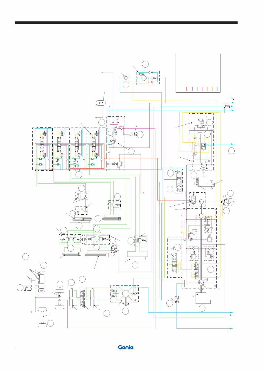
GTH 23007 AGRI 730 hydraulic schematic
M
X1
X2
G
MH
S
A
A
M
1
X
1
X
2
T
G
T 1
P S F a F a1 F e MB
T 2 R
B
B
U
MA
F S
CF EF
L
S
L
S
L R
T P
T R
Diesel engine
Hydrostatic transmission
pump max displacement: 56 cc / rev
Hydrostatic transmission motor
max displacement: 80 cc / rev
Flushing valve
Boom functions pump
with integrated priority valve
displacement: 34 cc/rev
Suction screen
Heat exchanger
Telescopic boom functions
main valve (4 sections)
Anticavitation valves
cracking pressure
5 bar
Check valve
cracking pressure
2.5 bar
Check valve
cracking pressure
8 bar
Oil tank capacity
at gauge level
82 liters
HYDRAULI C C IRCUI T
COLORS LEGENDA
Functions driving lines
Low pressure and transmission
charge pressure lines
Hydrostatic transmission
high pressure lines
Load sensing and piloting lines
Open circuits high pressure lines
Suction lines
Tank lines
Steering rotating actuator
displacement: 125 cc / rev.
Front axle
Service brake
circuit reservoir
Service brake
pedal pump
max operating
pressure: 80 bar
Forks levelling
slave cylinder
Forks tilt cylinder
Boom telescoping cylinder
Boom lift cylinder
Double overcenter safety valve
piloting ratio: 4.2 1
cracking pressure: 350 bar
/
/
Double overcenter safety valve
piloting ratio: 4.2 1
cracking pressure: 350 bar
/
/
Sing /
/
le overcenter safety valve
piloting ratio: 4.2 1
cracking pressure: 350 bar
Sing / le overcenter safety valve
piloting ratio: 4.2:1
cracking pressure: 350 bar
Cracking pressure
450 bar
Cracking pressure
450 bar
Cracking press.
30 bar
Cracking press.
430 bar
Max relief valve
cracking
pressure:
170 bar
Anti-shock
valves
cracking
pressure:
225 bar
Quick coupling
hydraulic ports
Forks attachment
quick coupling cylinder
Steering mode
selector valve
4 ways / 3 positions
Front axle
steering cylinder
Rear axle
steering cylinder
TP
5
TP
2
TP
1
Hydraulically piloted
double check valve
piloting ratio: 4 1 /
P1
P2
T
A
P
B
Shutoff valve
Service brake
pressure switch
activating pressure:
2,8-6,3 bar
Hydrostatic transmission
high pressure test port
Boom functions hydraulic
circuit test port
Service brake
circuit test port
Ev1
Ev3
Ev4
Ev2
Return filter
with suction line
pressurized at 0,5 bar
A1
B1
B3
A3
B2
A2
A4
B4
T
P PR PKB
Ps
MP
Acc
TP
MPR
PPZ
300 bar
170 bar
300 bar
280 bar
32 bar
0,5 mm
1 mm
RPP/A
RPP/A
RPP/A
RPP/A
RPP/B
RPP/B
Ev10
A
C
B
D
E
G
RPP/B
RPP/B
Ev5
RPM
VM
Parking brake
minimum pressure
pressure switch
activating pressure:
20 bar
Accumulator
capacity:
0.5 Litres
precharge
pressure:
35 bar
T P
A
B Ev 11
Ev12
Mechanical gearbox speeds
selector valve
4 ways/3 positions
Mechanical gearbox
speeds selector
actuator
Mechanical gearbox (2 speeds)
TP
3
Hydrostatic transmission
boost pressure test port
TP
4
Low pressure hydraulic
circuit test port
27
Rear axle
4
37
25
26
15
13
14
12
11
1
39
2
3
9
8
10
40
39
36
5
34
32
16
C
29
28
38
7
24
31
35
22
23
21
30
20
19
6
18
17
You're Reading a Preview
What's Included?
 Lifetime Access
Fast Download Speeds
Online & Offline Access
Access PDF Contents & Bookmarks
Full Search Facility
Print one or all pages of your manual
$46.99
GENIE GTH-2506 AGRI-625 GTH-3007 AGRI-730 Service Manual
Viewed 35 Times Today

What's Included?
Lifetime Access
Fast Download Speeds
Online & Offline Access
Access PDF Contents & Bookmarks
Full Search Facility
Print one or all pages of your manual
$46.99

Secure transaction
What's Included?
Lifetime Access
Fast Download Speeds
Online & Offline Access
Access PDF Contents & Bookmarks
Full Search Facility
Print one or all pages of your manual
Description
The Genie Telehandler manual provides essential information for the GTH-2506, AGRI-625, GTH-3007, and AGRI-730 models. This comprehensive guide is indispensable for professional mechanics and DIY enthusiasts alike. Whether you're conducting routine maintenance, troubleshooting, or making repairs, this manual equips you with the knowledge needed to keep your Genie Telehandler in optimal condition.


